Page 2028 of 2453

5AT-12
General Description
AUTOMATIC TRANSMISSION
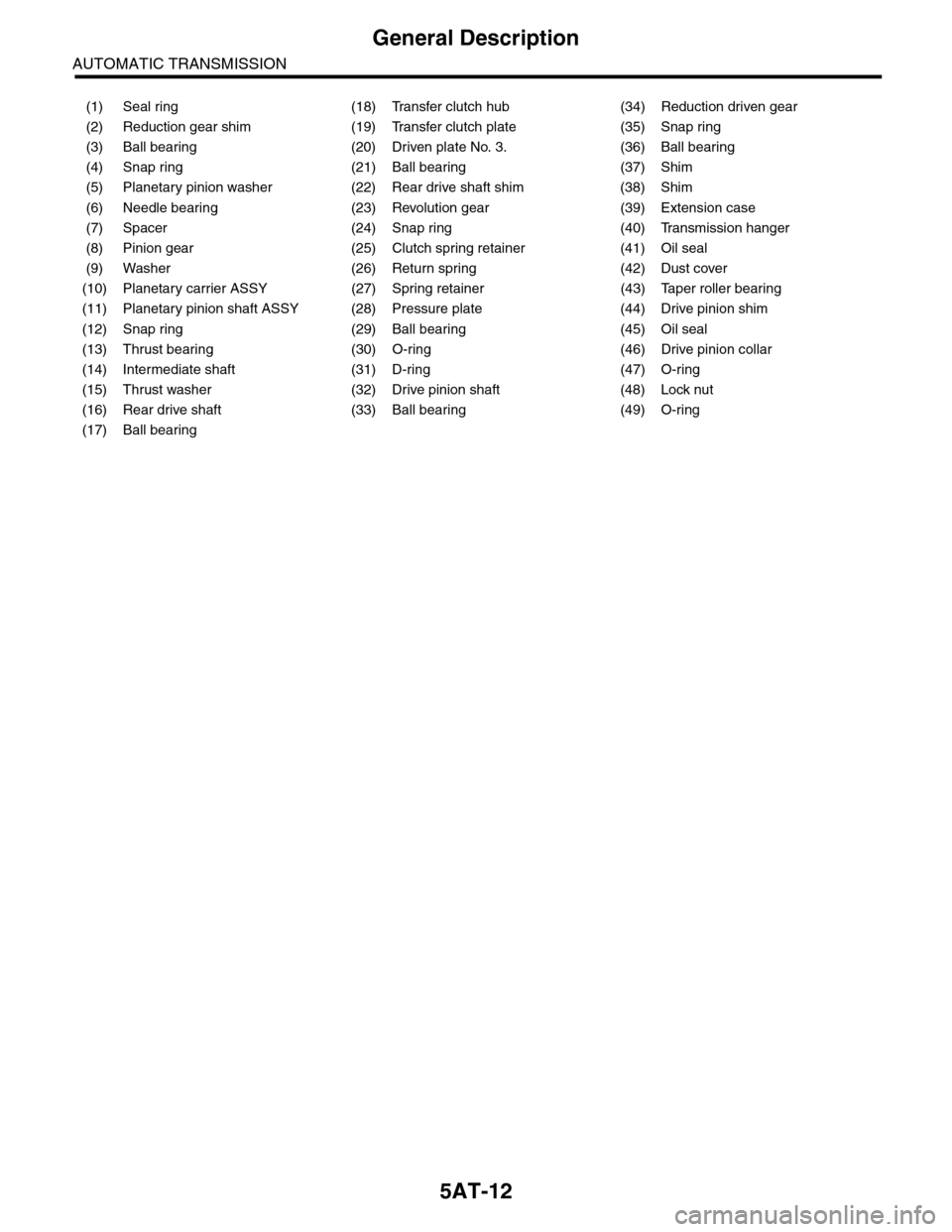
(1) Seal ring (18) Transfer clutch hub (34) Reduction driven gear
(2) Reduction gear shim (19) Transfer clutch plate (35) Snap ring
(3) Ball bearing (20) Driven plate No. 3. (36) Ball bearing
(4) Snap ring (21) Ball bearing (37) Shim
(5) Planetary pinion washer (22) Rear drive shaft shim (38) Shim
(6) Needle bearing (23) Revolution gear (39) Extension case
(7) Spacer (24) Snap ring (40) Transmission hanger
(8) Pinion gear (25) Clutch spring retainer (41) Oil seal
(9) Washer (26) Return spring (42) Dust cover
(10) Planetary carrier ASSY (27) Spring retainer (43) Taper roller bearing
(11) Planetary pinion shaft ASSY (28) Pressure plate (44) Drive pinion shim
(12) Snap ring (29) Ball bearing (45) Oil seal
(13) Thrust bearing (30) O-ring (46) Drive pinion collar
(14) Intermediate shaft (31) D-ring (47) O-ring
(15) Thrust washer (32) Drive pinion shaft (48) Lock nut
(16) Rear drive shaft (33) Ball bearing (49) O-ring
(17) Ball bearing
Page 2034 of 2453
5AT-18
General Description
AUTOMATIC TRANSMISSION
498897700 OIL PRESSURE
ADAPTER
Used for measuring transfer clutch pressure.
498545400 FILTER WRENCH Used for removing and installing the ATF filter.
498277200 STOPPER SET Used for removing and installing automatic
transmission assembly to engine.
41099AA010 ENGINE SUPPORT
BRACKET
Used for supporting engine.
41099AA020 ENGINE SUPPORT Used for supporting engine.
ILLUSTRATION TOOL NUMBER DESCRIPTION REMARKS
ST-498897700
ST-498545400
ST-498277200
ST41099AA010
ST41099AA020
Page 2039 of 2453
5AT-23
General Description
AUTOMATIC TRANSMISSION
18763AA000 COMPRESSOR
SHAFT
Used for disassembling multi-plate clutch for shift
transmission.
18765AA000 COMPRESSOR
SUPPORT
Used for disassembling multi-plate clutch for shift
transmission.
18676AA020TORX® WRENCHUsed for disassembling torque converter case.
18854AA000 ANGLE GAUGE Used for tightening parking support.
498077300 REMOVER Used for removing ball bearing of reduction
driven gear.
ILLUSTRATION TOOL NUMBER DESCRIPTION REMARKS
ST18763AA000
ST18765AA000
ST18676AA020
ST18854AA000
ST-498077300
Page 2040 of 2453
5AT-24
General Description
AUTOMATIC TRANSMISSION
499587100 OIL SEAL
INSTALLER
Used for installing the oil seal.
499787500 ADAPTER Used for removing and installing drive pinion lock
nut.
499575400 GAUGE Used for measuring height of total end play.
18762AA000 COMPRESSOR
SPECIAL TOOL
Used for disassembling multi-plate clutch for shift
transmission.
499755602
(Newly adopted tool)
PRESS Used for installing the parking gear.
ILLUSTRATION TOOL NUMBER DESCRIPTION REMARKS
ST-499587100
ST-499787500
ST-499575400
ST18762AA000
ST-499755602
Page 2041 of 2453

5AT-25
General Description
AUTOMATIC TRANSMISSION
2. GENERAL TOOL
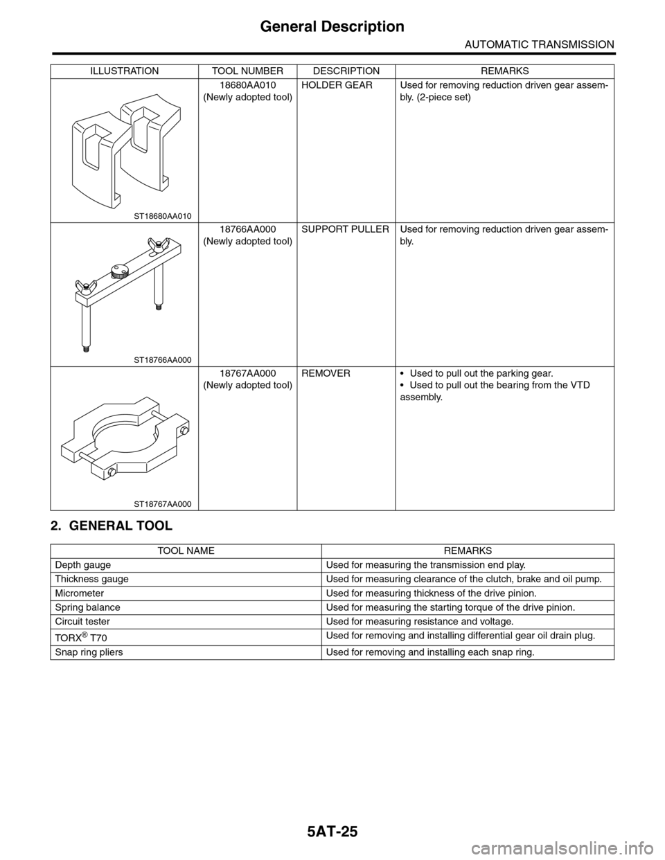
18680AA010
(Newly adopted tool)
HOLDER GEAR Used for removing reduction driven gear assem-
bly. (2-piece set)
18766AA000
(Newly adopted tool)
SUPPORT PULLER Used for removing reduction driven gear assem-
bly.
18767AA000
(Newly adopted tool)
REMOVER • Used to pull out the parking gear.
•Used to pull out the bearing from the VTD
assembly.
TO OL N AM E RE MA R KS
Depth gauge Used for measuring the transmission end play.
Thickness gauge Used for measuring clearance of the clutch, brake and oil pump.
Micrometer Used for measuring thickness of the drive pinion.
Spring balance Used for measuring the starting torque of the drive pinion.
Circuit tester Used for measuring resistance and voltage.
TO RX® T70Used for removing and installing differential gear oil drain plug.
Snap ring pliers Used for removing and installing each snap ring.
ILLUSTRATION TOOL NUMBER DESCRIPTION REMARKS
ST18680AA010
ST18766AA000
ST18767AA000
Page 2043 of 2453
5AT-27
Automatic Transmission Fluid
AUTOMATIC TRANSMISSION
C: CONDITION CHECK
NOTE:
When replacing ATF, check the inside condition of transmission body by inspecting the drained ATF.
Fluid condition Trouble and possible cause Corrective action
Large amount of metallic pieces are
found.
Internal metal parts of transmission body are
excessively wor n.
Replace ATF and check if AT operates
correctly.
Is thick and is a varnish-form fluid. Clutch etc. is burned.Replace ATF and check the AT body or
vehicle for faulty.
Clouded fluid or bubbles are found in
fluid.Water is mixed.Replace ATF and check the water enter-
ing point.
Page 2046 of 2453

5AT-30
Stall Test
AUTOMATIC TRANSMISSION
5. Stall Test
A: INSPECTION
NOTE:
The stall test is extremely important in diagnosing
the condition of an automatic transmission and en-
gine. It should be conducted to measure the engine
stall speeds in “R” and “2nd of manual mode”.
Purposes of the stall test:
•Operational check of the automatic transmission
clutch
•Operational check of the torque converter clutch
•Engine performance check
1) Check that the throttle valve fully opens.
2) Check that the engine oil level is correct.
3) Check that the coolant level is correct.
4) Check that the ATF level is correct.
5) Check that the differential gear oil level is cor-
rect.
6) Raise the ATF temperature to 70 to 80°C (158 to
176°F) by driving a distance of 5 to 10 km (3 to 6
miles). Confirm the ATF temperature on Subaru
Select Monitor.
RENT DATA, OPERATION, Subaru Select Moni-
tor.>
7) Place the wheel chocks at the front and rear of
all wheels and apply the parking brake.
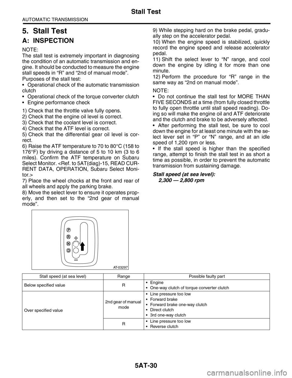
8) Move the select lever to ensure it operates prop-
erly, and then set to the “2nd gear of manual
mode”.
9) While stepping hard on the brake pedal, gradu-
ally step on the accelerator pedal.
10) When the engine speed is stabilized, quickly
record the engine speed and release accelerator
pedal.
11) Shift the select lever to “N” range, and cool
down the engine by idling it for more than one
minute.
12) Perform the procedure for “R” range in the
same way as “2nd on manual mode”.
NOTE:
•Do not continue the stall test for MORE THAN
FIVE SECONDS at a time (from fully closed throttle
to fully open throttle until stall speed reading). Do-
ing so will make the engine oil and ATF deteriorate
and the clutch and brake to be adversely affected.
•After performing the stall test, be sure to cool
down the engine for at least one minute with the se-
lect lever set in “P” or “N” range, and at an idle
speed of 1,200 rpm or less.
•If the stall speed is higher than the specified
range, attempt to finish the stall test in as short a
time as possible, in order to prevent the automatic
transmission from sustaining damage.
Stall speed (at sea level):
2,300 — 2,800 rpm
AT-03297
Stall speed (at sea level) Range Possible faulty part
Below specified value R•Engine
•One-way clutch of torque converter clutch
Over specified value
2nd gear of manual
mode
•Line pressure too low
•Forward brake
•Forward brake one-way clutch
•Direct clutch
•3rd one-way clutch
R•Line pressure too low
•Reverse clutch
Page 2047 of 2453

5AT-31
Time Lag Test
AUTOMATIC TRANSMISSION
6. Time Lag Test
A: INSPECTION
NOTE:
When the select lever is shifted while the engine is
idling, there will be a certain time elapse or lag be-
fore shock is felt. Using this, check the condition of
forward brake, reverse brake, 1st one-way clutch,
forward one-way clutch and 3rd one-way clutch.
•Perform the test at normal operation fluid tem-
perature of 70 — 80°C (158 — 176°F).
•Be sure to allow a one minute interval between
tests.
•Make three measurements and take the average
value.
1) Fully apply the parking brake.
2) Start the engine.
Check the idle speed (A/C OFF).
3) Shift the select lever from “N” to “D” range. Using
a stop watch, measure the time-lag from shifting
the lever until the shock is felt.
Time-lag
Specification: 1.2 sec. or less
If “N” → “D” time-lag is longer than specification:
•Line pressure too low
•Forward brake worn
•One–way clutch not operating properly
4) In the same manner, measure the time lag of “N”
→ “R”.
Time-lag
Specification: 1.5 sec. or less
If “N” → “R” time lag is longer than specification:
•Line pressure too low
•Reverse brake worn