2009 SUBARU TRIBECA clutch
[x] Cancel search: clutchPage 2249 of 2453
5AT(diag)-132
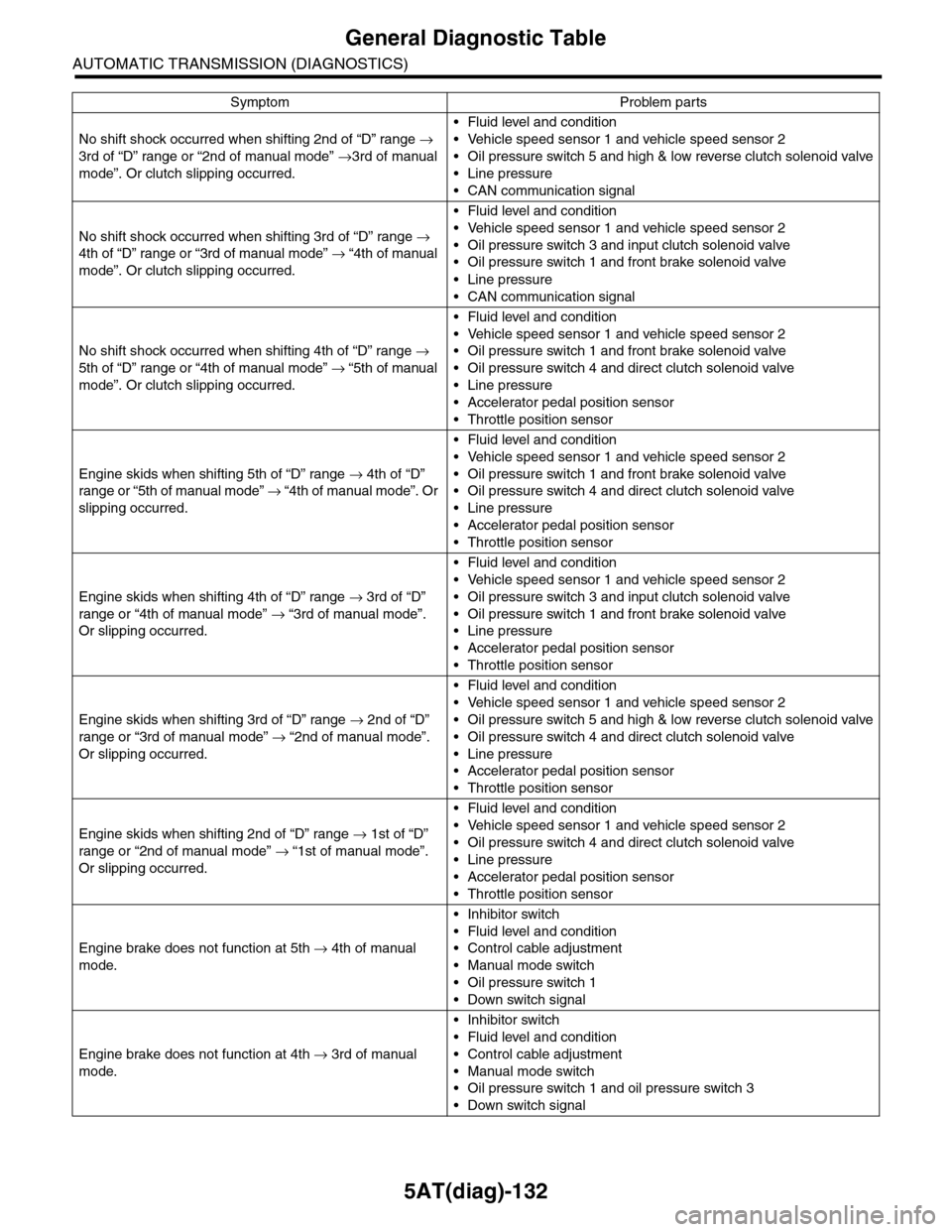
General Diagnostic Table
AUTOMATIC TRANSMISSION (DIAGNOSTICS)
No shift shock occurred when shifting 2nd of “D” range →
3rd of “D” range or “2nd of manual mode” →3rd of manual
mode”. Or clutch slipping occurred.
•Fluid level and condition
•Vehicle speed sensor 1 and vehicle speed sensor 2
•Oil pressure switch 5 and high & low reverse clutch solenoid valve
•Line pressure
•CAN communication signal
No shift shock occurred when shifting 3rd of “D” range →
4th of “D” range or “3rd of manual mode” → “4th of manual
mode”. Or clutch slipping occurred.
•Fluid level and condition
•Vehicle speed sensor 1 and vehicle speed sensor 2
•Oil pressure switch 3 and input clutch solenoid valve
•Oil pressure switch 1 and front brake solenoid valve
•Line pressure
•CAN communication signal
No shift shock occurred when shifting 4th of “D” range →
5th of “D” range or “4th of manual mode” → “5th of manual
mode”. Or clutch slipping occurred.
•Fluid level and condition
•Vehicle speed sensor 1 and vehicle speed sensor 2
•Oil pressure switch 1 and front brake solenoid valve
•Oil pressure switch 4 and direct clutch solenoid valve
•Line pressure
•Accelerator pedal position sensor
•Throttle position sensor
Engine skids when shifting 5th of “D” range → 4th of “D”
range or “5th of manual mode” → “ 4 t h of ma nua l mo d e” . O r
slipping occurred.
•Fluid level and condition
•Vehicle speed sensor 1 and vehicle speed sensor 2
•Oil pressure switch 1 and front brake solenoid valve
•Oil pressure switch 4 and direct clutch solenoid valve
•Line pressure
•Accelerator pedal position sensor
•Throttle position sensor
Engine skids when shifting 4th of “D” range → 3rd of “D”
range or “4th of manual mode” → “3rd of manual mode”.
Or slipping occurred.
•Fluid level and condition
•Vehicle speed sensor 1 and vehicle speed sensor 2
•Oil pressure switch 3 and input clutch solenoid valve
•Oil pressure switch 1 and front brake solenoid valve
•Line pressure
•Accelerator pedal position sensor
•Throttle position sensor
Engine skids when shifting 3rd of “D” range → 2nd of “D”
range or “3rd of manual mode” → “2nd of manual mode”.
Or slipping occurred.
•Fluid level and condition
•Vehicle speed sensor 1 and vehicle speed sensor 2
•Oil pressure switch 5 and high & low reverse clutch solenoid valve
•Oil pressure switch 4 and direct clutch solenoid valve
•Line pressure
•Accelerator pedal position sensor
•Throttle position sensor
Engine skids when shifting 2nd of “D” range → 1st of “D”
range or “2nd of manual mode” → “1st of manual mode”.
Or slipping occurred.
•Fluid level and condition
•Vehicle speed sensor 1 and vehicle speed sensor 2
•Oil pressure switch 4 and direct clutch solenoid valve
•Line pressure
•Accelerator pedal position sensor
•Throttle position sensor
Engine brake does not function at 5th → 4th of manual
mode.
•Inhibitor switch
•Fluid level and condition
•Control cable adjustment
•Manual mode switch
•Oil pressure switch 1
•Down switch signal
Engine brake does not function at 4th → 3rd of manual
mode.
•Inhibitor switch
•Fluid level and condition
•Control cable adjustment
•Manual mode switch
•Oil pressure switch 1 and oil pressure switch 3
•Down switch signal
Symptom Problem parts
Page 2250 of 2453
5AT(diag)-133
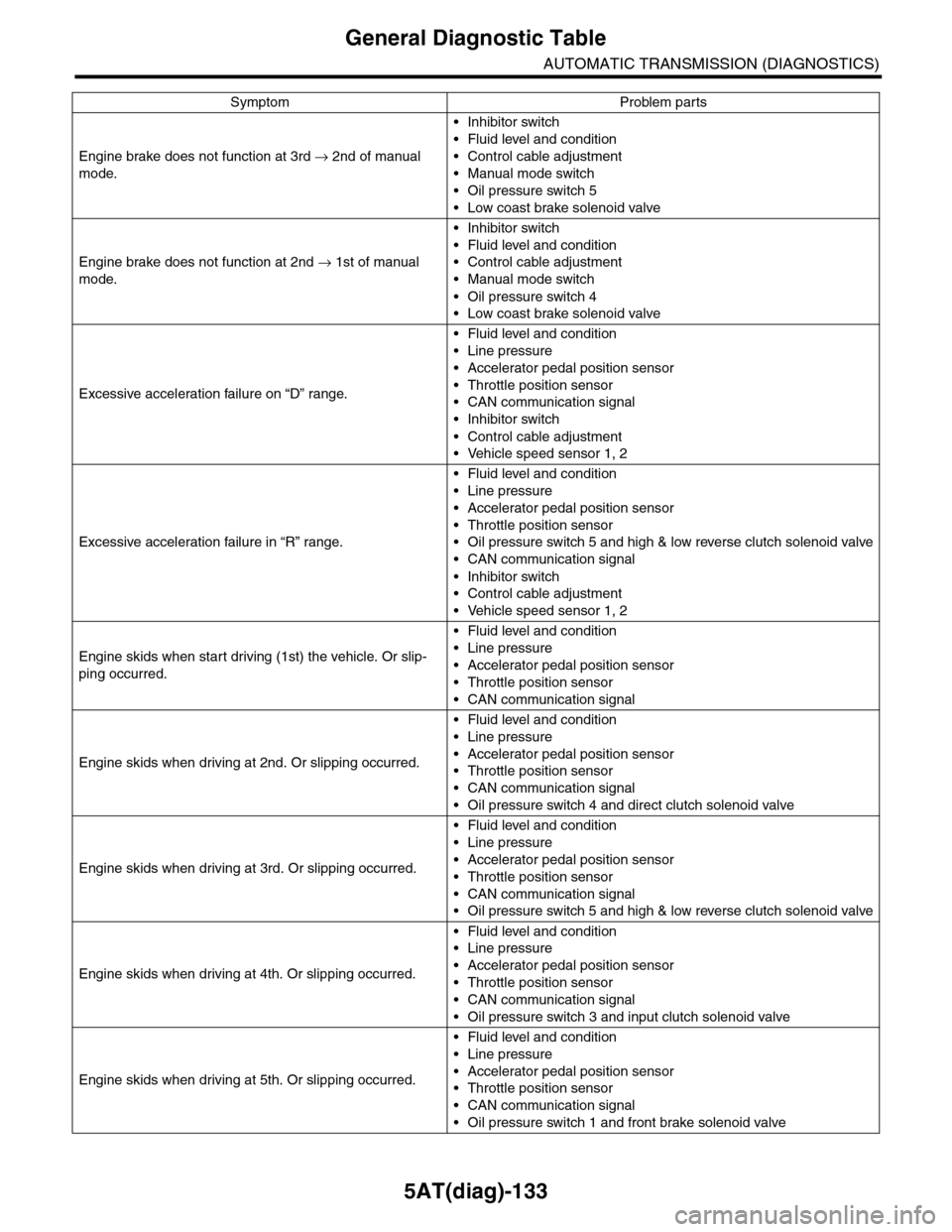
General Diagnostic Table
AUTOMATIC TRANSMISSION (DIAGNOSTICS)
Engine brake does not function at 3rd → 2nd of manual
mode.
•Inhibitor switch
•Fluid level and condition
•Control cable adjustment
•Manual mode switch
•Oil pressure switch 5
•Low coast brake solenoid valve
Engine brake does not function at 2nd → 1st of manual
mode.
•Inhibitor switch
•Fluid level and condition
•Control cable adjustment
•Manual mode switch
•Oil pressure switch 4
•Low coast brake solenoid valve
Excessive acceleration failure on “D” range.
•Fluid level and condition
•Line pressure
•Accelerator pedal position sensor
•Throttle position sensor
•CAN communication signal
•Inhibitor switch
•Control cable adjustment
•Vehicle speed sensor 1, 2
Excessive acceleration failure in “R” range.
•Fluid level and condition
•Line pressure
•Accelerator pedal position sensor
•Throttle position sensor
•Oil pressure switch 5 and high & low reverse clutch solenoid valve
•CAN communication signal
•Inhibitor switch
•Control cable adjustment
•Vehicle speed sensor 1, 2
Engine skids when start driving (1st) the vehicle. Or slip-
ping occurred.
•Fluid level and condition
•Line pressure
•Accelerator pedal position sensor
•Throttle position sensor
•CAN communication signal
Engine skids when driving at 2nd. Or slipping occurred.
•Fluid level and condition
•Line pressure
•Accelerator pedal position sensor
•Throttle position sensor
•CAN communication signal
•Oil pressure switch 4 and direct clutch solenoid valve
Engine skids when driving at 3rd. Or slipping occurred.
•Fluid level and condition
•Line pressure
•Accelerator pedal position sensor
•Throttle position sensor
•CAN communication signal
•Oil pressure switch 5 and high & low reverse clutch solenoid valve
Engine skids when driving at 4th. Or slipping occurred.
•Fluid level and condition
•Line pressure
•Accelerator pedal position sensor
•Throttle position sensor
•CAN communication signal
•Oil pressure switch 3 and input clutch solenoid valve
Engine skids when driving at 5th. Or slipping occurred.
•Fluid level and condition
•Line pressure
•Accelerator pedal position sensor
•Throttle position sensor
•CAN communication signal
•Oil pressure switch 1 and front brake solenoid valve
Symptom Problem parts
Page 2251 of 2453
5AT(diag)-134
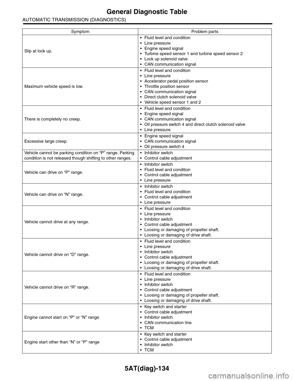
General Diagnostic Table
AUTOMATIC TRANSMISSION (DIAGNOSTICS)
Slip at lock up.
•Fluid level and condition
•Line pressure
•Engine speed signal
•Turbine speed sensor 1 and turbine speed sensor 2
•Lock up solenoid valve
•CAN communication signal
Maximum vehicle speed is low.
•Fluid level and condition
•Line pressure
•Accelerator pedal position sensor
•Throttle position sensor
•CAN communication signal
•Direct clutch solenoid valve
•Vehicle speed sensor 1 and 2
There is completely no creep.
•Fluid level and condition
•Engine speed signal
•CAN communication signal
•Oil pressure switch 4 and direct clutch solenoid valve
•Line pressure
Excessive large creep.
•Engine speed signal
•CAN communication signal
•Oil pressure switch 4
Ve h i c l e c a n n o t b e p a r k i n g c o n d i t i o n o n “ P ” r a n g e . Pa r k i n g
condition is not released though shifting to other ranges.
•Inhibitor switch
•Control cable adjustment
Ve h i c l e c a n d r i v e o n “ P ” r a n g e .
•Inhibitor switch
•Fluid level and condition
•Control cable adjustment
•Line pressure
Ve h i c l e c a n d r i v e o n “ N ” r a n g e .
•Inhibitor switch
•Fluid level and condition
•Control cable adjustment
•Line pressure
Ve h i c l e c a n n o t d r i v e a t a n y r a n g e .
•Fluid level and condition
•Line pressure
•Inhibitor switch
•Control cable adjustment
•Loosing or damaging of propeller shaft.
•Loosing or damaging of drive shaft.
Ve h i c l e c a n n o t d r i v e o n “ D ” r a n g e .
•Fluid level and condition
•Line pressure
•Inhibitor switch
•Control cable adjustment
•Loosing or damaging of propeller shaft.
•Loosing or damaging of drive shaft.
Ve h i c l e c a n n o t d r i v e o n “ R ” r a n g e .
•Fluid level and condition
•Line pressure
•Inhibitor switch
•Control cable adjustment
•Loosing or damaging of propeller shaft.
•Loosing or damaging of drive shaft.
Engine cannot start on “P” or “N” range
•Key switch and starter
•Control cable adjustment
•Inhibitor switch
•CAN communication line
•TCM
Engine start other than “N” or “P” range
•Key switch and starter
•Control cable adjustment
•Inhibitor switch
•TCM
Symptom Problem parts
Page 2347 of 2453
WI-63
Air Conditioning System
WIRING SYSTEM
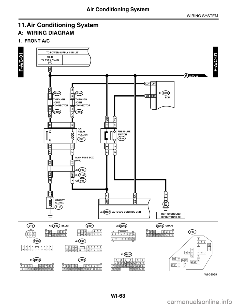
11.Air Conditioning System
A: WIRING DIAGRAM
1. FRONT A/C
WI-08069
F-A/C-01F-A/C-01
FB-46F/B FUSE NO. 22 (IG)
TO POWER SUPPLY CIRCUIT
LOr
YB
GOr
ECM
C:B136
B
PRESSURESWITCH
F110
MAGNETCLUTCH
B282A:AUTO A/C CONTROL UNIT
A10
YGOr
A9
(BLUE)C:
C:
A:
B:
A-A/C-02A
C9
C33
Y
1
B
2
B10
4
GOrYB
3A/CRELAY HOLDER
LG
29
Y
31
F27
2830
B10
4213
F35
123456789101112
B361
1723456891011121314
F37
12345678910 11 12 13 14 15 16 17 18 19 20
B143
1234 5678910 11 12 13 14 15 16 17 18 19 20
F109
3412 8910 1112 13 14 15 16 17 18 19 20 21 22 23 24567
F108
1923 810411 12 13 14 15 165671718
F27
13141516 17
27
24 252620 212223
29303128
89101112
12534
7
6
1918
A:
B:
F37
B143
C:F35
MAIN FUSE BOX(M/B)
A4
LGY
B13
C3C7
B136
16101112131415252430
9871718192028212223293231
123456
2726333435
LOr
14
LOr 9
THROUGHJOINTCONNECTOR
B361
F108
GOr
1
GOr
11
THROUGHJOINTCONNECTOR
B360
F109
(GRAY)B360
12345678910111213141516
REF. TO GROUNDCIRCUIT [GND-03]
A:B282
12345678
910 1112 1314 1516
Page 2434 of 2453
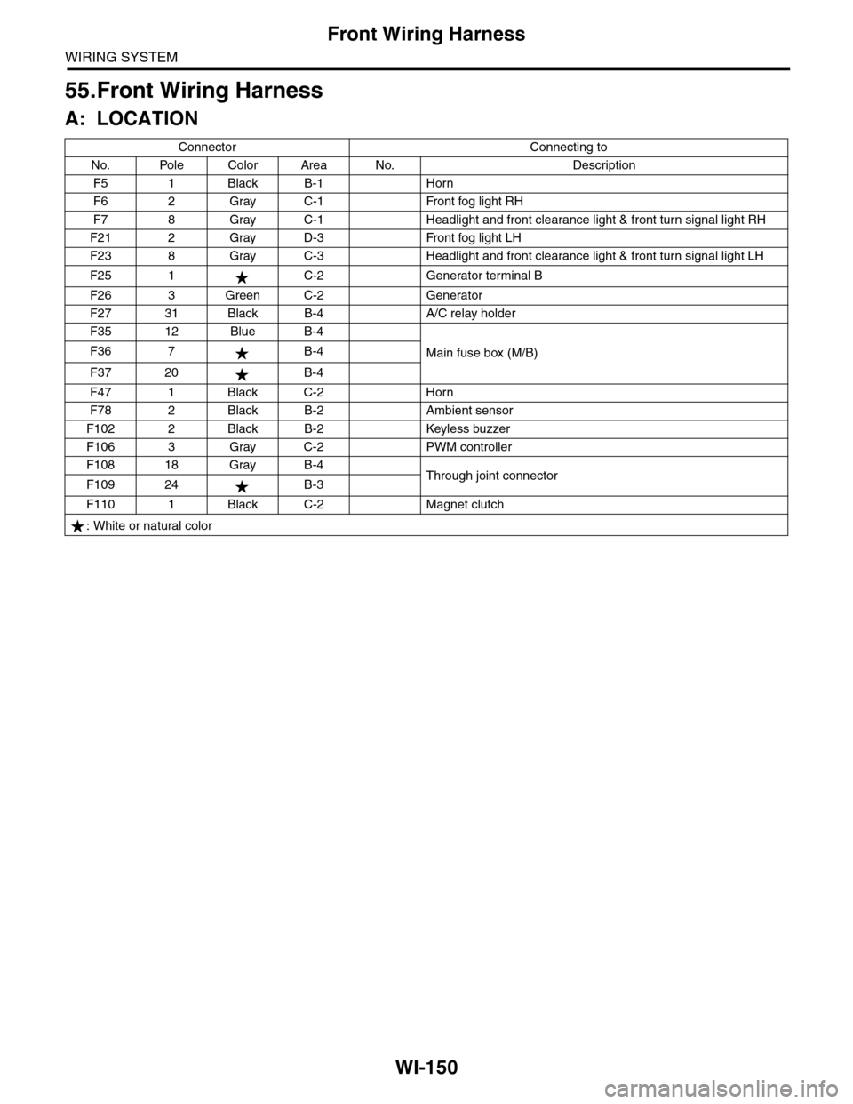
WI-150
Front Wiring Harness
WIRING SYSTEM
55.Front Wiring Harness
A: LOCATION
Connector Connecting to
No. Pole Color Area No. Description
F5 1 Black B-1 Horn
F6 2 Gray C-1 Front fog light RH
F7 8 Gray C-1 Headlight and front clearance light & front turn signal light RH
F21 2 Gray D-3 Front fog light LH
F23 8 Gray C-3 Headlight and front clearance light & front turn signal light LH
F25 1 C-2 Generator terminal B
F26 3 Green C-2 Generator
F27 31 Black B-4 A/C relay holder
F35 12 Blue B-4
Main fuse box (M/B)F36 7 B-4
F37 20 B-4
F47 1 Black C-2 Horn
F78 2 Black B-2 Ambient sensor
F102 2 Black B-2 Keyless buzzer
F106 3 Gray C-2 PWM controller
F108 18 Gray B-4Through joint connectorF109 24 B-3
F110 1 Black C-2 Magnet clutch
: White or natural color