2009 SUBARU TRIBECA clutch
[x] Cancel search: clutchPage 1149 of 2453
CO(H6DO)-30
Engine Cooling System Trouble in General
COOLING
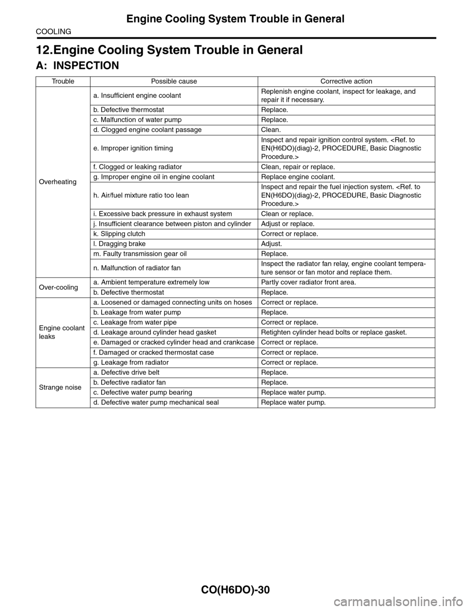
12.Engine Cooling System Trouble in General
A: INSPECTION
Tr o u b l e P o s s i b l e c a u s e C o r r e c t i v e a c t i o n
Overheating
a. Insufficient engine coolantReplenish engine coolant, inspect for leakage, and
repair it if necessary.
b. De fe c ti ve t he r mo st a t Rep la c e.
c. Malfunction of water pump Replace.
d. Clogged engine coolant passage Clean.
e. Improper ignition timing
Inspect and repair ignition control system.
Procedure.>
f. Clogged or leaking radiator Clean, repair or replace.
g. Improper engine oil in engine coolant Replace engine coolant.
h. Air/fuel mixture ratio too lean
Inspect and repair the fuel injection system.
Procedure.>
i. Excessive back pressure in exhaust system Clean or replace.
j. Insufficient clearance between piston and cylinder Adjust or replace.
k. Slipping clutch Correct or replace.
l. Dragging brake Adjust.
m. Faulty transmission gear oil Replace.
n. Malfunction of radiator fanInspect the radiator fan relay, engine coolant tempera-
ture sensor or fan motor and replace them.
Over-coolinga. Ambient temperature extremely low Partly cover radiator front area.
b. De fe c ti ve t he r mo st a t Rep la c e.
Engine coolant
leaks
a. Loosened or damaged connecting units on hoses Correct or replace.
b. L ea k ag e f r o m wat e r pu mp Rep la c e.
c. Leakage from water pipe Correct or replace.
d. Leakage around cylinder head gasket Retighten cylinder head bolts or replace gasket.
e. Damaged or cracked cylinder head and crankcase Correct or replace.
f. Damaged or cracked ther mostat case Correct or replace.
g. Leakage from radiator Correct or replace.
Strange noise
a. Defective drive belt Replace.
b. De fe c ti ve ra di a t or fan Rep la c e.
c. Defective water pump bearing Replace water pump.
d. Defective water pump mechanical seal Replace water pump.
Page 1198 of 2453
EN(H6DO)(diag)-37
Inspection Mode
ENGINE (DIAGNOSTICS)
1. PREPARATION FOR THE INSPECTION
MODE
1) Check battery voltage is more than 12 V and fuel
remains half [20 to 40 2 (5.3 to 10.6 US gal, 4.4 to
8.8 Imp gal)].
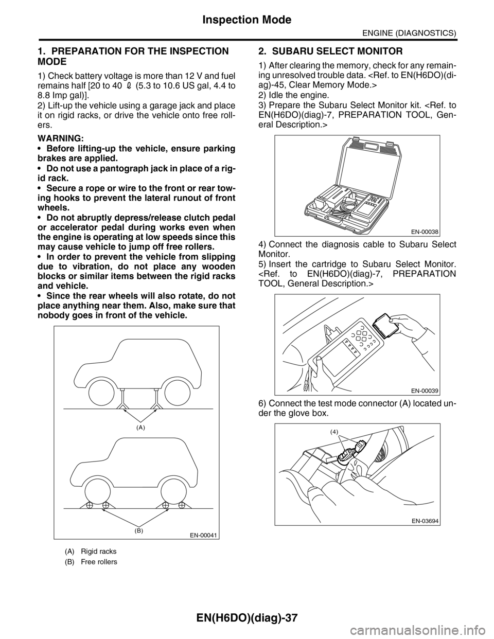
2) Lift-up the vehicle using a garage jack and place
it on rigid racks, or drive the vehicle onto free roll-
ers.
WARNING:
•Before lifting-up the vehicle, ensure parking
brakes are applied.
•Do not use a pantograph jack in place of a rig-
id rack.
•Secure a rope or wire to the front or rear tow-
ing hooks to prevent the lateral runout of front
wheels.
•Do not abruptly depress/release clutch pedal
or accelerator pedal during works even when
the engine is operating at low speeds since this
may cause vehicle to jump off free rollers.
•In order to prevent the vehicle from slipping
due to vibration, do not place any wooden
blocks or similar items between the rigid racks
and vehicle.
•Since the rear wheels will also rotate, do not
place anything near them. Also, make sure that
nobody goes in front of the vehicle.
2. SUBARU SELECT MONITOR
1) After clearing the memory, check for any remain-
ing unresolved trouble data.
2) Idle the engine.
3) Prepare the Subaru Select Monitor kit.
eral Description.>
4) Connect the diagnosis cable to Subaru Select
Monitor.
5) Insert the cartridge to Subaru Select Monitor.
6) Connect the test mode connector (A) located un-
der the glove box.
(A) Rigid racks
(B) Free rollers
EN-00041
(A)
(B)
EN-00038
EN-00039
EN-03694
(4)
Page 1880 of 2453
ME(H6DO)-14
General Description
MECHANICAL
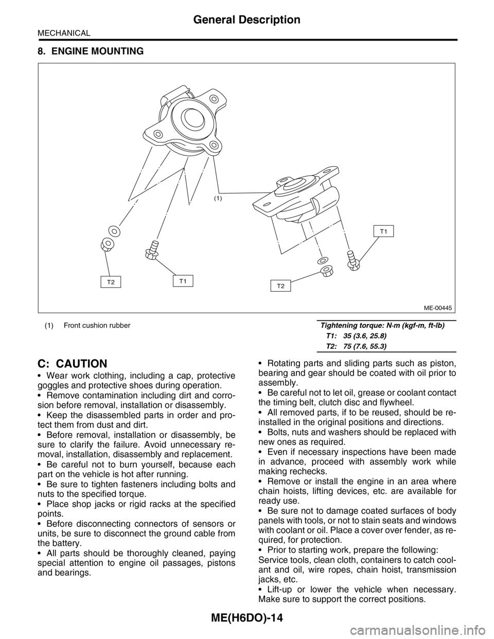
8. ENGINE MOUNTING
C: CAUTION
•Wear work clothing, including a cap, protective
goggles and protective shoes during operation.
•Remove contamination including dirt and corro-
sion before removal, installation or disassembly.
•Keep the disassembled parts in order and pro-
tect them from dust and dirt.
•Before removal, installation or disassembly, be
sure to clarify the failure. Avoid unnecessary re-
moval, installation, disassembly and replacement.
•Be careful not to burn yourself, because each
part on the vehicle is hot after running.
•Be sure to tighten fasteners including bolts and
nuts to the specified torque.
•Place shop jacks or rigid racks at the specified
points.
•Before disconnecting connectors of sensors or
units, be sure to disconnect the ground cable from
the battery.
•All parts should be thoroughly cleaned, paying
special attention to engine oil passages, pistons
and bearings.
•Rotating parts and sliding parts such as piston,
bearing and gear should be coated with oil prior to
assembly.
•Be careful not to let oil, grease or coolant contact
the timing belt, clutch disc and flywheel.
•All removed parts, if to be reused, should be re-
installed in the original positions and directions.
•Bolts, nuts and washers should be replaced with
new ones as required.
•Even if necessary inspections have been made
in advance, proceed with assembly work while
making rechecks.
•Remove or install the engine in an area where
chain hoists, lifting devices, etc. are available for
ready use.
•Be sure not to damage coated surfaces of body
panels with tools, or not to stain seats and windows
with coolant or oil. Place a cover over fender, as re-
quired, for protection.
•Prior to starting work, prepare the following:
Service tools, clean cloth, containers to catch cool-
ant and oil, wire ropes, chain hoist, transmission
jacks, etc.
•Lift-up or lower the vehicle when necessary.
Make sure to support the correct positions.
(1) Front cushion rubber Tightening torque: N·m (kgf-m, ft-lb)
T1: 35 (3.6, 25.8)
T2: 75 (7.6, 55.3)
(1)
T2
T1
T1T2
ME-00445
Page 1900 of 2453
ME(H6DO)-34
Engine Assembly
MECHANICAL
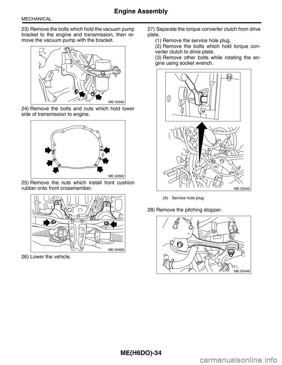
23) Remove the bolts which hold the vacuum pump
bracket to the engine and transmission, then re-
move the vacuum pump with the bracket.
24) Remove the bolts and nuts which hold lower
side of transmission to engine.
25) Remove the nuts which install front cushion
rubber onto front crossmember.
26) Lower the vehicle.
27) Separate the torque converter clutch from drive
plate.
(1) Remove the service hole plug.
(2) Remove the bolts which hold torque con-
verter clutch to drive plate.
(3) Remove other bolts while rotating the en-
gine using socket wrench.
28) Remove the pitching stopper.
ME-02660
ME-02662
ME-00485
(A) Service hole plug
(A)
ME-02445
ME-02446
Page 1901 of 2453
ME(H6DO)-35
Engine Assembly
MECHANICAL
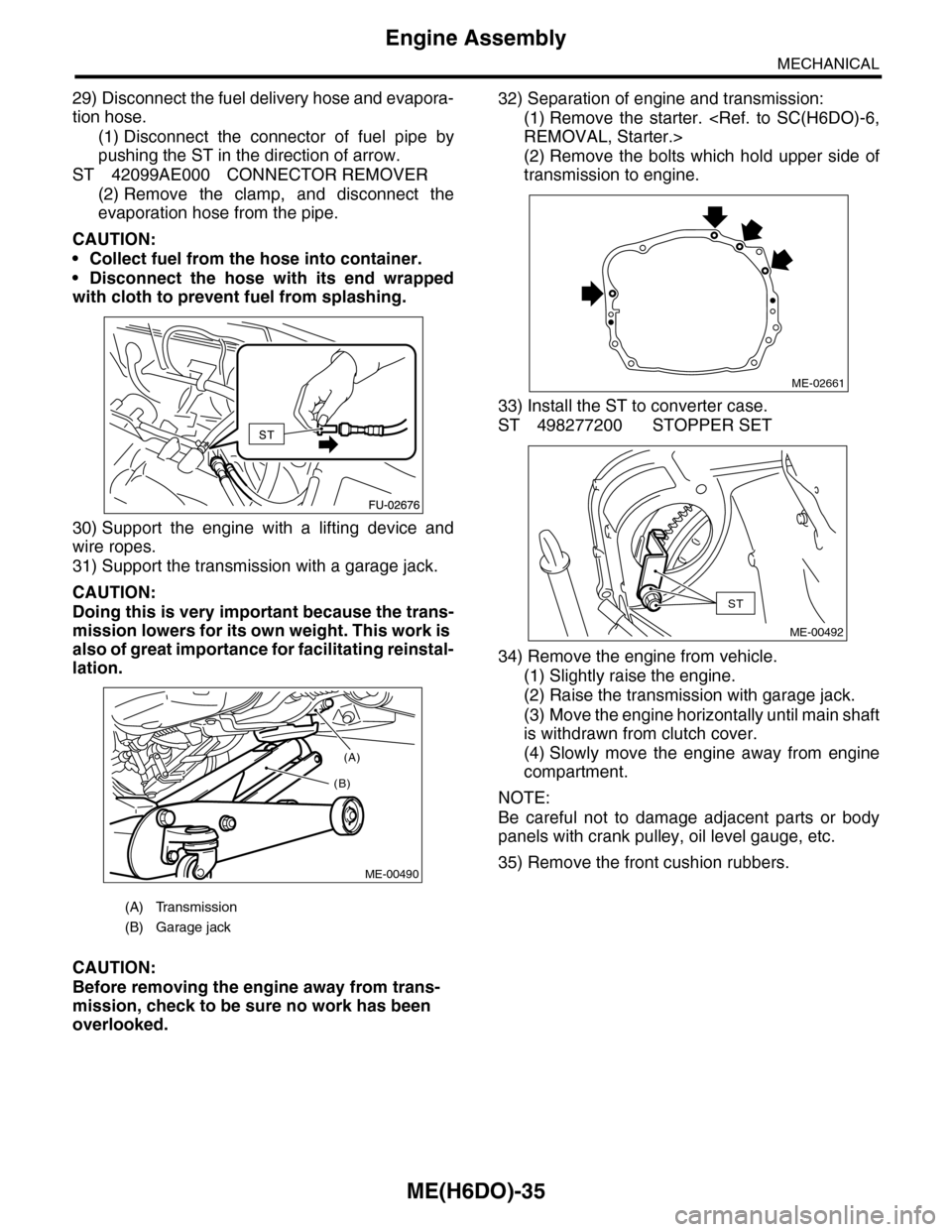
29) Disconnect the fuel delivery hose and evapora-
tion hose.
(1) Disconnect the connector of fuel pipe by
pushing the ST in the direction of arrow.
ST 42099AE000 CONNECTOR REMOVER
(2) Remove the clamp, and disconnect the
evaporation hose from the pipe.
CAUTION:
•Collect fuel from the hose into container.
•Disconnect the hose with its end wrapped
with cloth to prevent fuel from splashing.
30) Support the engine with a lifting device and
wire ropes.
31) Support the transmission with a garage jack.
CAUTION:
Doing this is very important because the trans-
mission lowers for its own weight. This work is
also of great importance for facilitating reinstal-
lation.
CAUTION:
Before removing the engine away from trans-
mission, check to be sure no work has been
overlooked.
32) Separation of engine and transmission:
(1) Remove the starter.
(2) Remove the bolts which hold upper side of
transmission to engine.
33) Install the ST to converter case.
ST 498277200 STOPPER SET
34) Remove the engine from vehicle.
(1) Slightly raise the engine.
(2) Raise the transmission with garage jack.
(3) Move the engine horizontally until main shaft
is withdrawn from clutch cover.
(4) Slowly move the engine away from engine
compartment.
NOTE:
Be careful not to damage adjacent parts or body
panels with crank pulley, oil level gauge, etc.
35) Remove the front cushion rubbers.
(A) Transmission
(B) Garage jack
(A)
(B)
ME-00490
ME-02661
ST
ME-00492
Page 1902 of 2453
ME(H6DO)-36
Engine Assembly
MECHANICAL
B: INSTALLATION
1) Install the front cushion rubbers.
Tightening torque:
35 N·m (3.6 kgf-m, 25.8 ft-lb)
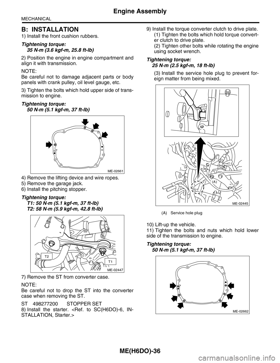
2) Position the engine in engine compartment and
align it with transmission.
NOTE:
Be careful not to damage adjacent parts or body
panels with crank pulley, oil level gauge, etc.
3) Tighten the bolts which hold upper side of trans-
mission to engine.
Tightening torque:
50 N·m (5.1 kgf-m, 37 ft-lb)
4) Remove the lifting device and wire ropes.
5) Remove the garage jack.
6) Install the pitching stopper.
Tightening torque:
T1: 50 N·m (5.1 kgf-m, 37 ft-lb)
T2: 58 N·m (5.9 kgf-m, 42.8 ft-lb)
7) Remove the ST from converter case.
NOTE:
Be careful not to drop the ST into the converter
case when removing the ST.
ST 498277200 STOPPER SET
8) Install the starter.
9) Install the torque converter clutch to drive plate.
(1) Tighten the bolts which hold torque convert-
er clutch to drive plate.
(2) Tighten other bolts while rotating the engine
using socket wrench.
Tightening torque:
25 N·m (2.5 kgf-m, 18 ft-lb)
(3) Install the service hole plug to prevent for-
eign matter from being mixed.
10) Lift-up the vehicle.
11) Tighten the bolts and nuts which hold lower
side of the transmission to engine.
Tightening torque:
50 N·m (5.1 kgf-m, 37 ft-lb)
ME-02661
T2
T1
ME-02447
(A) Service hole plug
(A)
ME-02445
ME-02662
Page 1961 of 2453
SC(H6DO)-3
General Description
STARTING/CHARGING SYSTEMS
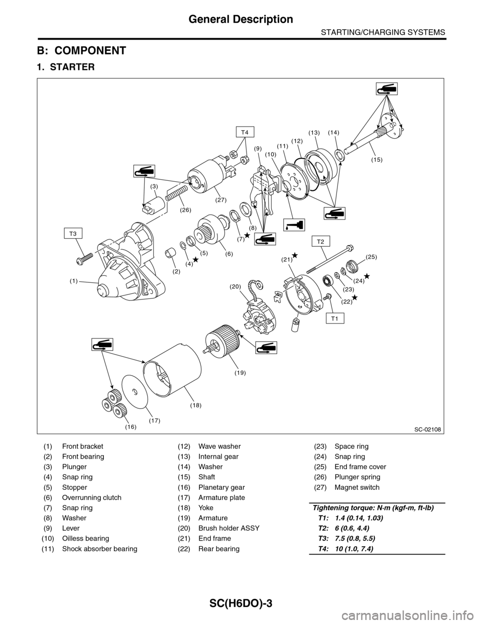
B: COMPONENT
1. STARTER
(1) Front bracket (12) Wave washer (23) Space ring
(2) Front bearing (13) Internal gear (24) Snap ring
(3) Plunger (14) Washer (25) End frame cover
(4) Snap ring (15) Shaft (26) Plunger spring
(5) Stopper (16) Planetary gear (27) Magnet switch
(6) Overrunning clutch (17) Armature plate
(7) Snap ring (18) YokeTightening torque: N·m (kgf-m, ft-lb)
(8) Washer (19) ArmatureT1: 1.4 (0.14, 1.03)
(9) Lever (20) Brush holder ASSYT2: 6 (0.6, 4.4)
(10) Oilless bearing (21) End frameT3: 7.5 (0.8, 5.5)
(11) Shock absorber bearing (22) Rear bearingT4: 10 (1.0, 7.4)
SC-02108
T3
T1
T2
(1)
(2)
T4
(4)(21)
(22)
(23)
(24)
(25)(5)(6)
(7)
(8)
(15)
(14)(13)
(12)(11)
(10)(9)
(3)
(26)
(27)
(16)(17)
(18)
(19)
(20)
Page 1966 of 2453
SC(H6DO)-8
Starter
STARTING/CHARGING SYSTEMS
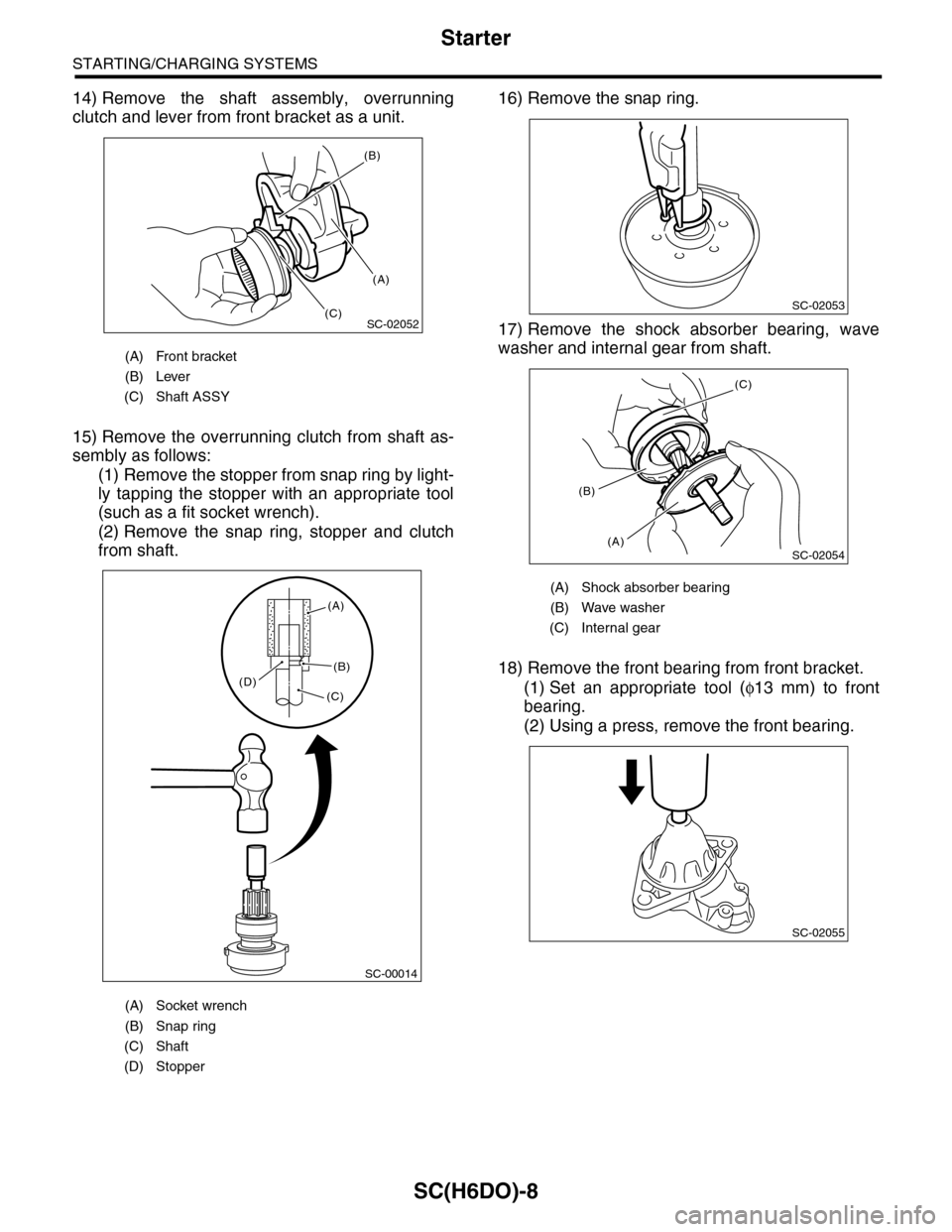
14) Remove the shaft assembly, overrunning
clutch and lever from front bracket as a unit.
15) Remove the overrunning clutch from shaft as-
sembly as follows:
(1) Remove the stopper from snap ring by light-
ly tapping the stopper with an appropriate tool
(such as a fit socket wrench).
(2) Remove the snap ring, stopper and clutch
from shaft.
16) Remove the snap ring.
17) Remove the shock absorber bearing, wave
washer and internal gear from shaft.
18) Remove the front bearing from front bracket.
(1) Set an appropriate tool (φ13 mm) to front
bearing.
(2) Using a press, remove the front bearing.
(A) Front bracket
(B) Lever
(C) Shaft ASSY
(A) Socket wrench
(B) Snap ring
(C) Shaft
(D) Stopper
SC-02052
(B)
(A)
(C)
SC-00014
(A)
(B)
(C)(D)
(A) Shock absorber bearing
(B) Wave washer
(C) Internal gear
SC-02053
SC-02054
(C)
(A)
(B)
SC-02055