2009 SUBARU TRIBECA clutch
[x] Cancel search: clutchPage 2048 of 2453
5AT-32
Line Pressure Test
AUTOMATIC TRANSMISSION
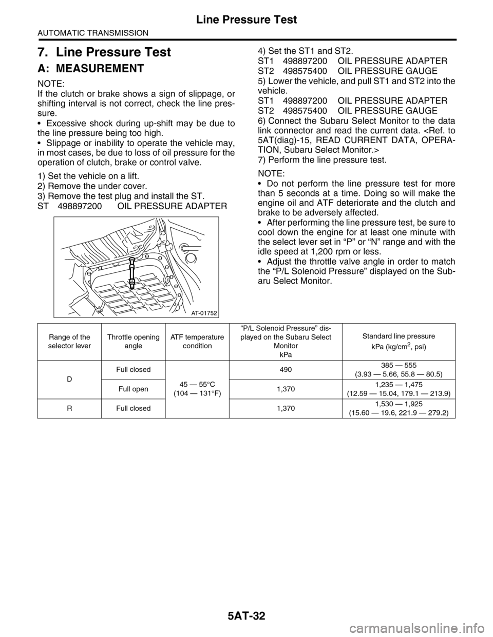
7. Line Pressure Test
A: MEASUREMENT
NOTE:
If the clutch or brake shows a sign of slippage, or
shifting interval is not correct, check the line pres-
sure.
•Excessive shock during up-shift may be due to
the line pressure being too high.
•Slippage or inability to operate the vehicle may,
in most cases, be due to loss of oil pressure for the
operation of clutch, brake or control valve.
1) Set the vehicle on a lift.
2) Remove the under cover.
3) Remove the test plug and install the ST.
ST 498897200 OIL PRESSURE ADAPTER
4) Set the ST1 and ST2.
ST1 498897200 OIL PRESSURE ADAPTER
ST2 498575400 OIL PRESSURE GAUGE
5) Lower the vehicle, and pull ST1 and ST2 into the
vehicle.
ST1 498897200 OIL PRESSURE ADAPTER
ST2 498575400 OIL PRESSURE GAUGE
6) Connect the Subaru Select Monitor to the data
link connector and read the current data.
TION, Subaru Select Monitor.>
7) Perform the line pressure test.
NOTE:
•Do not perform the line pressure test for more
than 5 seconds at a time. Doing so will make the
engine oil and ATF deteriorate and the clutch and
brake to be adversely affected.
•After performing the line pressure test, be sure to
cool down the engine for at least one minute with
the select lever set in “P” or “N” range and with the
idle speed at 1,200 rpm or less.
•Adjust the throttle valve angle in order to match
the “P/L Solenoid Pressure” displayed on the Sub-
aru Select Monitor.
AT-01752
Range of the
selector lever
Throttle opening
angle
AT F t e m p e r a t u r e
condition
“P/L Solenoid Pressure” dis-
played on the Subaru Select
Monitor
kPa
Standard line pressure
kPa (kg/cm2, psi)
D
Full closed
45 — 55°C
(104 — 131°F)
490385 — 555
(3.93 — 5.66, 55.8 — 80.5)
Full open 1,3701,235 — 1,475
(12.59 — 15.04, 179.1 — 213.9)
RFull closed 1,3701,530 — 1,925
(15.60 — 19.6, 221.9 — 279.2)
Page 2049 of 2453
5AT-33
Transfer Clutch Pressure Test
AUTOMATIC TRANSMISSION
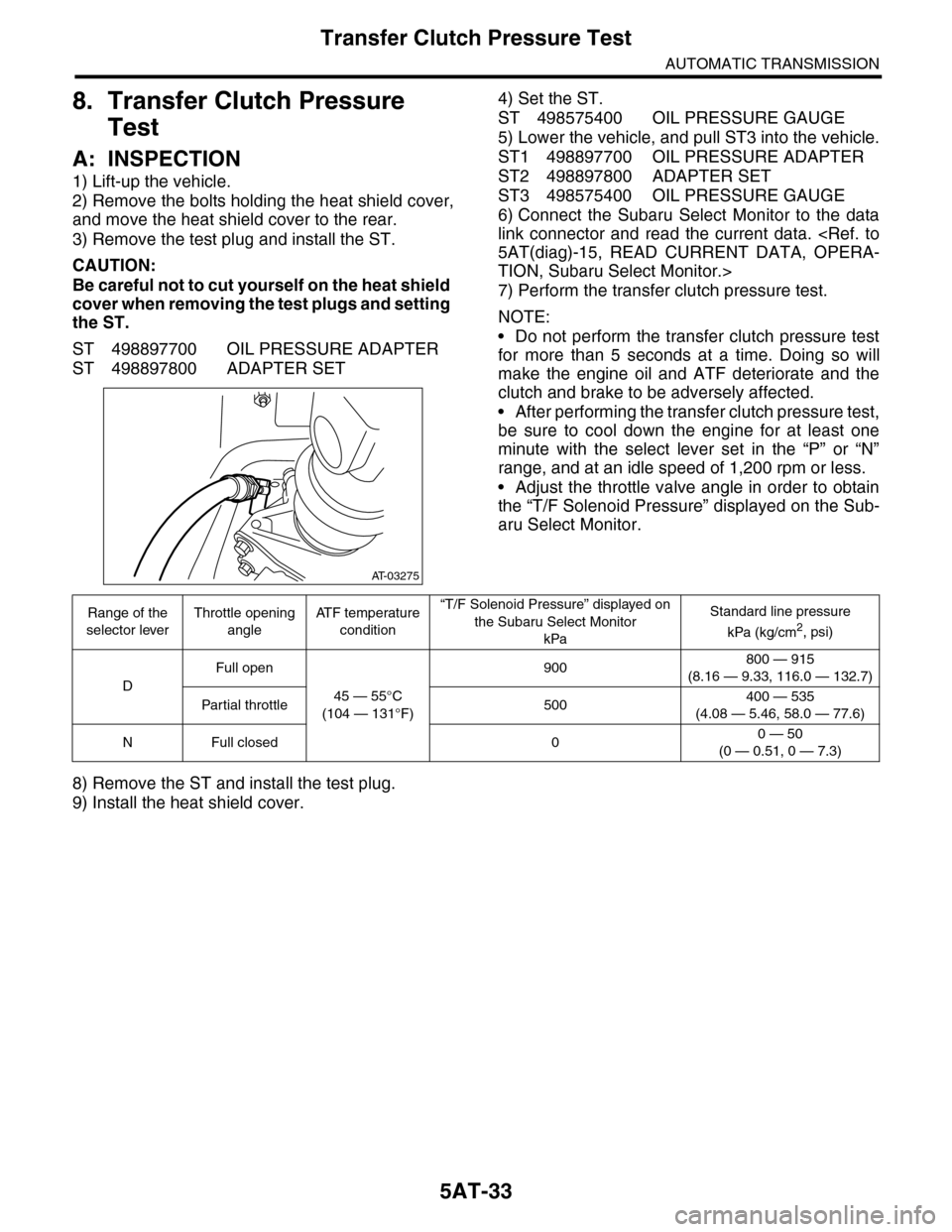
8. Transfer Clutch Pressure
Test
A: INSPECTION
1) Lift-up the vehicle.
2) Remove the bolts holding the heat shield cover,
and move the heat shield cover to the rear.
3) Remove the test plug and install the ST.
CAUTION:
Be careful not to cut yourself on the heat shield
cover when removing the test plugs and setting
the ST.
ST 498897700 OIL PRESSURE ADAPTER
ST 498897800 ADAPTER SET
4) Set the ST.
ST 498575400 OIL PRESSURE GAUGE
5) Lower the vehicle, and pull ST3 into the vehicle.
ST1 498897700 OIL PRESSURE ADAPTER
ST2 498897800 ADAPTER SET
ST3 498575400 OIL PRESSURE GAUGE
6) Connect the Subaru Select Monitor to the data
link connector and read the current data.
TION, Subaru Select Monitor.>
7) Perform the transfer clutch pressure test.
NOTE:
•Do not perform the transfer clutch pressure test
for more than 5 seconds at a time. Doing so will
make the engine oil and ATF deteriorate and the
clutch and brake to be adversely affected.
•After performing the transfer clutch pressure test,
be sure to cool down the engine for at least one
minute with the select lever set in the “P” or “N”
range, and at an idle speed of 1,200 rpm or less.
•Adjust the throttle valve angle in order to obtain
the “T/F Solenoid Pressure” displayed on the Sub-
aru Select Monitor.
8) Remove the ST and install the test plug.
9) Install the heat shield cover.
AT-03275
Range of the
selector lever
Throttle opening
angle
AT F t e m p e r a t u r e
condition
“T/F Solenoid Pressure” displayed on
the Subaru Select Monitor
kPa
Standard line pressure
kPa (kg/cm2, psi)
D
Full open
45 — 55°C
(104 — 131°F)
900800 — 915
(8.16 — 9.33, 116.0 — 132.7)
Par tial throttle 500400 — 535
(4.08 — 5.46, 58.0 — 77.6)
NFull closed 00 — 50
(0 — 0.51, 0 — 7.3)
Page 2052 of 2453
5AT-36
Automatic Transmission Assembly
AUTOMATIC TRANSMISSION
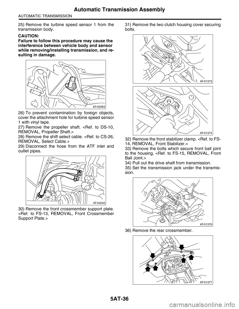
25) Remove the turbine speed sensor 1 from the
transmission body.
CAUTION:
Failure to follow this procedure may cause the
interference between vehicle body and sensor
while removing/installing transmission, and re-
sulting in damage.
26) To prevent contamination by foreign objects,
cover the attachment hole for turbine speed sensor
1 with vinyl tape.
27) Remove the propeller shaft.
28) Remove the shift select cable.
29) Disconnect the hose from the ATF inlet and
outlet pipes.
30) Remove the front crossmember support plate.
31) Remove the two clutch housing cover securing
bolts.
32) Remove the front stabilizer clamp.
33) Remove the bolts which secure front ball joint
to the housing.
34) Pull out the drive shaft from transmission.
35) Set the transmission jack under the transmis-
sion.
36) Remove the rear crossmember.
AT-03363
AT-03246
AT-01373
AT-01374
AT-01376
AT-01377
Page 2055 of 2453
5AT-39
Automatic Transmission Assembly
AUTOMATIC TRANSMISSION
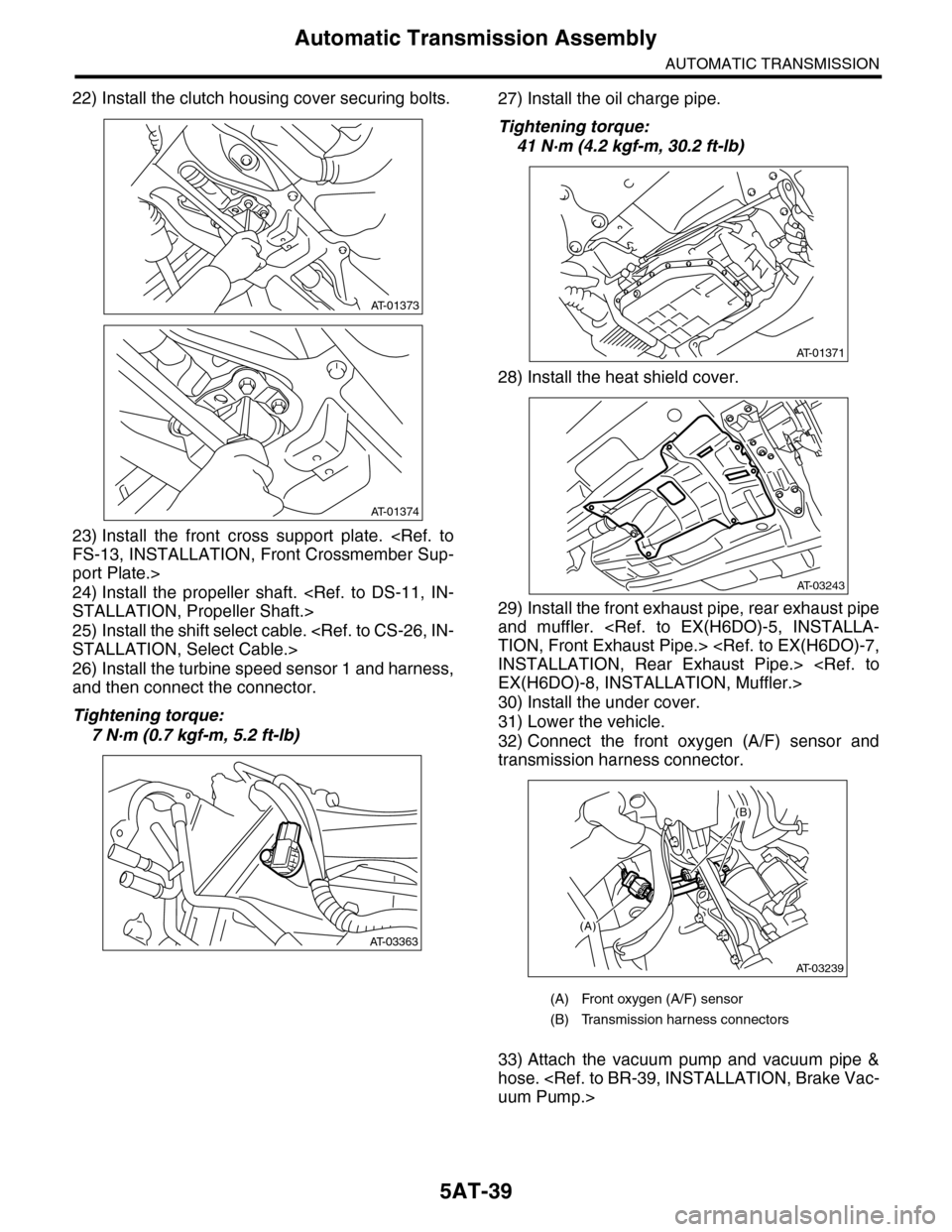
22) Install the clutch housing cover securing bolts.
23) Install the front cross support plate.
port Plate.>
24) Install the propeller shaft.
25) Install the shift select cable.
26) Install the turbine speed sensor 1 and harness,
and then connect the connector.
Tightening torque:
7 N·m (0.7 kgf-m, 5.2 ft-lb)
27) Install the oil charge pipe.
Tightening torque:
41 N·m (4.2 kgf-m, 30.2 ft-lb)
28) Install the heat shield cover.
29) Install the front exhaust pipe, rear exhaust pipe
and muffler.
30) Install the under cover.
31) Lower the vehicle.
32) Connect the front oxygen (A/F) sensor and
transmission harness connector.
33) Attach the vacuum pump and vacuum pipe &
hose.
AT-01373
AT-01374
AT-03363
(A) Front oxygen (A/F) sensor
(B) Transmission harness connectors
AT-01371
AT-03243
(A)
(B)
AT-03239
Page 2079 of 2453
5AT-63
Extension Case
AUTOMATIC TRANSMISSION
24.Extension Case
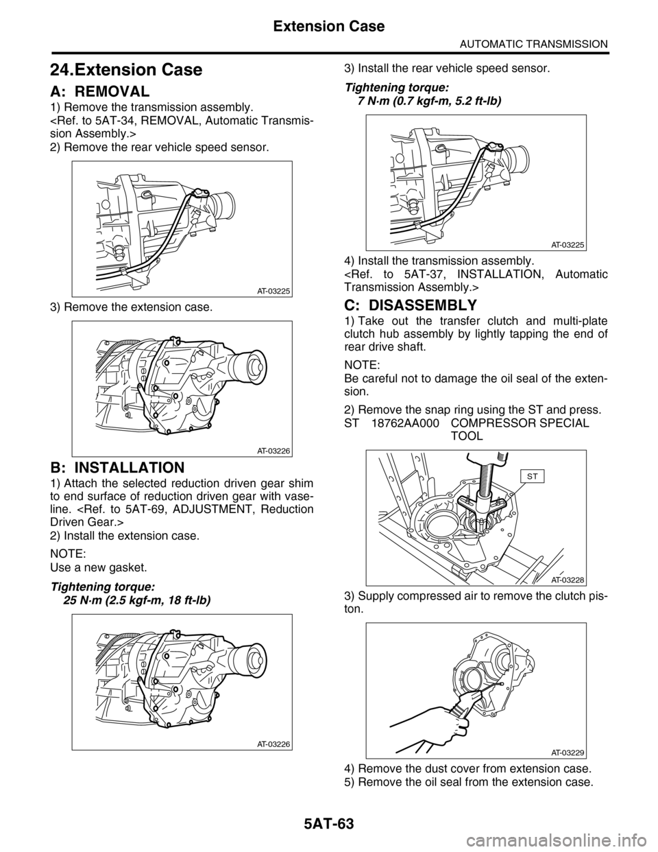
A: REMOVAL
1) Remove the transmission assembly.
2) Remove the rear vehicle speed sensor.
3) Remove the extension case.
B: INSTALLATION
1) Attach the selected reduction driven gear shim
to end surface of reduction driven gear with vase-
line.
2) Install the extension case.
NOTE:
Use a new gasket.
Tightening torque:
25 N·m (2.5 kgf-m, 18 ft-lb)
3) Install the rear vehicle speed sensor.
Tightening torque:
7 N·m (0.7 kgf-m, 5.2 ft-lb)
4) Install the transmission assembly.
C: DISASSEMBLY
1) Take out the transfer clutch and multi-plate
clutch hub assembly by lightly tapping the end of
rear drive shaft.
NOTE:
Be careful not to damage the oil seal of the exten-
sion.
2) Remove the snap ring using the ST and press.
ST 18762AA000 COMPRESSOR SPECIAL
TOOL
3) Supply compressed air to remove the clutch pis-
ton.
4) Remove the dust cover from extension case.
5) Remove the oil seal from the extension case.
AT-03225
AT-03226
AT-03226
AT-03225
AT-03228
ST
AT-03229
Page 2080 of 2453
5AT-64
Extension Case
AUTOMATIC TRANSMISSION
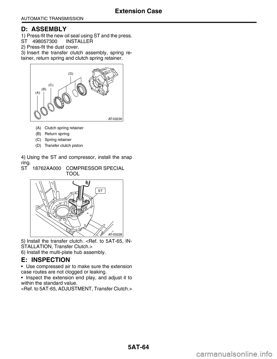
D: ASSEMBLY
1) Press-fit the new oil seal using ST and the press.
ST 498057300 INSTALLER
2) Press-fit the dust cover.
3) Insert the transfer clutch assembly, spring re-
tainer, return spring and clutch spring retainer.
4) Using the ST and compressor, install the snap
ring.
ST 18762AA000 COMPRESSOR SPECIAL
TOOL
5) Install the transfer clutch.
6) Install the multi-plate hub assembly.
E: INSPECTION
•Use compressed air to make sure the extension
case routes are not clogged or leaking.
•Inspect the extension end play, and adjust it to
within the standard value.
(A) Clutch spring retainer
(B) Return spring
(C) Spring retainer
(D) Transfer clutch piston
AT-03230
(A)(B)(C)
(D)
AT-03228
ST
Page 2081 of 2453
5AT-65
Transfer Clutch
AUTOMATIC TRANSMISSION
25.Transfer Clutch
A: REMOVAL
1) Remove the transmission assembly from vehicle
body.
2) Remove the extension case, and then remove
the transfer clutch.
B: INSTALLATION
1) Select the rear drive shaft shim.
2) Select driven plate No. 3.
3) Install the extension case.
4) Install the transmission assembly to the vehicle.
C: INSPECTION
•Inspect the drive plate facing for wear and dam-
age.
•Make sure the snap ring is not worn and the re-
turn spring has no permanent distortion, damage,
or deformation.
•Check that the D-ring is not damaged.
•Inspect the extension end play, and adjust it to
within the standard value.
D: ADJUSTMENT
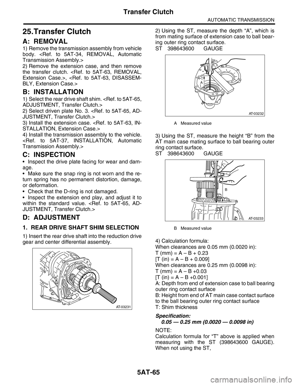
1. REAR DRIVE SHAFT SHIM SELECTION
1) Insert the rear drive shaft into the reduction drive
gear and center differential assembly.
2) Using the ST, measure the depth “A”, which is
from mating surface of extension case to ball bear-
ing outer ring contact surface.
ST 398643600 GAUGE
3) Using the ST, measure the height “B” from the
AT main case mating surface to ball bearing outer
ring contact surface.
ST 398643600 GAUGE
4) Calculation formula:
When clearances are 0.05 mm (0.0020 in):
T (mm) = A – B + 0.23
[T (in) = A – B + 0.009]
When clearances are 0.25 mm (0.0098 in):
T (mm) = A – B +0.03
[T (in) = A – B +0.001]
A: Depth from end of extension case to ball bearing
outer ring contact surface
B: Height from end of AT main case contact surface
to the ball bearing outer ring contact surface
T: Shim thickness
Specification:
0.05 — 0.25 mm (0.0020 — 0.0098 in)
NOTE:
Calculation formula for “T” above is applied when
measuring with the ST (398643600 GAUGE).
When not using the ST,
AT-03231
AMeasured value
BMeasured value
AT-03232
A
AT-03233
B
Page 2082 of 2453
5AT-66
Transfer Clutch
AUTOMATIC TRANSMISSION
When clearances are 0.05 mm (0.0020 in):
T (mm) = (A – α) – ((B – β) – 0.28) – 0.05
[T (in) = (A – α) – ((B – β) – 0.011) – 0.0020]
When clearances are 0.25 mm (0.0098 in):
T (mm) = (A – α) – ((B – β) – 0.28) – 0.25
[T (in) = (A – α) – ((B – β) – 0.011) – 0.0098]
is applied.
T: Shim thickness
A: Depth from end of extension case to ball bearing
outer ring contact surface
B: Height from end of AT main case contact surface
to the ball bearing outer ring contact surface
α: Thickness of collar used when measuring “A”
β: Thickness of collar used when measuring “B”
0.28 (0.011): Gasket thickness (Unit mm (in))
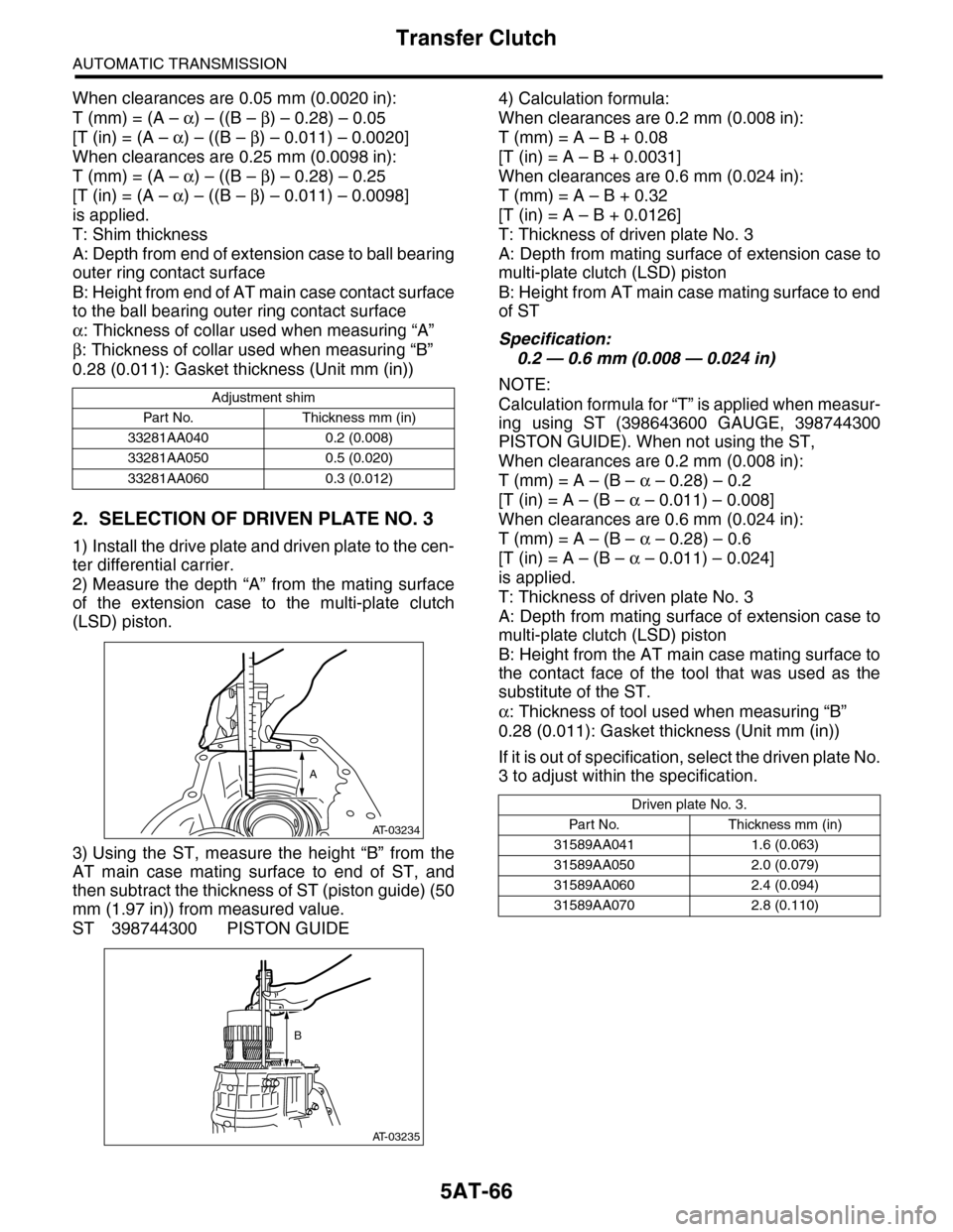
2. SELECTION OF DRIVEN PLATE NO. 3
1) Install the drive plate and driven plate to the cen-
ter differential carrier.
2) Measure the depth “A” from the mating surface
of the extension case to the multi-plate clutch
(LSD) piston.
3) Using the ST, measure the height “B” from the
AT main case mating surface to end of ST, and
then subtract the thickness of ST (piston guide) (50
mm (1.97 in)) from measured value.
ST 398744300 PISTON GUIDE
4) Calculation formula:
When clearances are 0.2 mm (0.008 in):
T (mm) = A – B + 0.08
[T (in) = A – B + 0.0031]
When clearances are 0.6 mm (0.024 in):
T (mm) = A – B + 0.32
[T (in) = A – B + 0.0126]
T: Thickness of driven plate No. 3
A: Depth from mating surface of extension case to
multi-plate clutch (LSD) piston
B: Height from AT main case mating surface to end
of ST
Specification:
0.2 — 0.6 mm (0.008 — 0.024 in)
NOTE:
Calculation formula for “T” is applied when measur-
ing using ST (398643600 GAUGE, 398744300
PISTON GUIDE). When not using the ST,
When clearances are 0.2 mm (0.008 in):
T (mm) = A – (B – α – 0.28) – 0.2
[T (in) = A – (B – α – 0.011) – 0.008]
When clearances are 0.6 mm (0.024 in):
T (mm) = A – (B – α – 0.28) – 0.6
[T (in) = A – (B – α – 0.011) – 0.024]
is applied.
T: Thickness of driven plate No. 3
A: Depth from mating surface of extension case to
multi-plate clutch (LSD) piston
B: Height from the AT main case mating surface to
the contact face of the tool that was used as the
substitute of the ST.
α: Thickness of tool used when measuring “B”
0.28 (0.011): Gasket thickness (Unit mm (in))
If it is out of specification, select the driven plate No.
3 to adjust within the specification.
Adjustment shim
Par t No. Thickness mm (in)
33281AA040 0.2 (0.008)
33281AA050 0.5 (0.020)
33281AA060 0.3 (0.012)
AT-03234
A
AT-03235
B
Driven plate No. 3.
Par t N o. Thickness mm (in)
31589AA041 1.6 (0.063)
31589AA050 2.0 (0.079)
31589AA060 2.4 (0.094)
31589AA070 2.8 (0.110)