2009 SUBARU TRIBECA relay
[x] Cancel search: relayPage 781 of 2453

BVC(diag)-26
Diagnostic Procedure with Diagnostic Trouble Code (DTC)
BRAKE VACUUM CONTROL (BVC) (DIAGNOSTICS)
E: DTC 22 DISCREPANCY IN RELAYS (OFF)
DTC DETECTING CONDITION:
Brake vacuum pump relay malfunction
TROUBLE SYMPTOM:
Vacuum pump does not operate properly.
WIRING DIAGRAM:
BR-00528
2
1
B25B
B422
1234
B432
2
1
4
36
5
8
7
B432
SBF HOLDER
3
7
14
21
53
43
VC2
VC3
B422
B422
VC3
RELAY BOX(VACUUMPUMP RELAY)
B417
VAC U U MPUMP
26
41
B47
MAINRELAY
B411
VAC U U M S E N S O RECM
A: B134B: B135C: B136
C23B30B22A27C8312
JOINT CONNECTOR
B424
**
B417B411
213
B: C:B135
5672134
29
101112131415252416
30
98171819202821222332312627333435
B136
16101112131415252430
9871718192028212223293231
123456
2726333435
VC2
A:B134
85610 11 12 13 14 157213416
3019 20 2228 29
91718252123 24323126 2733 34
B424
34561278
(BROWN)
21
5436
B47
* : TERMINAL NO. OPTIONAL ARRANGEMENT
21
SBF-7BATTERY
30A
3412
5
8967
10131211
14
Page 782 of 2453

BVC(diag)-27
Diagnostic Procedure with Diagnostic Trouble Code (DTC)
BRAKE VACUUM CONTROL (BVC) (DIAGNOSTICS)
Step Check Yes No
1CHECK BRAKE VACUUM PUMP RELAY.
1) Turn the ignition switch to OFF.
2) Remove the brake vacuum pump relay from
the relay box.
3) Connect the battery to terminals No. 1 and
No. 3 of the brake vacuum pump relay.
4) Measure the resistance between the brake
vacuum pump relay terminals.
Te r m i n a l s
No. 4 — No. 5:
Is the resistance less than 1
Ω?
Go to step 2.Replace the brake
vacuum pump
relay.
2CHECK BRAKE VACUUM PUMP RELAY
POWER SUPPLY.
1) Turn the ignition switch to ON.
2) Measure the voltage between brake vac-
uum pump relay connector and chassis
ground.
Connector & terminal
(VC2) No. 1 (+) — Chassis ground (–):
(VC2) No. 4 (+) — Chassis ground (–):
Is the voltage more than 10 V? Go to step 3.Repair the open or
ground short cir-
cuit of power sup-
ply circuit.
3CHECK HARNESS BETWEEN ECM AND
BRAKE VACUUM PUMP RELAY CONNEC-
TOR.
1) Turn the ignition switch to OFF.
2) Disconnect the connector of ECM.
3) Measure the resistance of the harness
between ECM and the brake vacuum pump
relay connector.
Connector & terminal
(B136) No. 8 — (VC2) No. 3:
(B135) No. 25 — (VC2) No. 5:
Is the resistance less than 1
Ω?
Go to step 4.Repair the open
circuit of harness
between ECM and
the brake vacuum
pump relay con-
nector.
4CHECK HARNESS BETWEEN THE BRAKE
VACUUM PUMP AND BRAKE VACUUM
PUMP RELAY CONNECTOR.
1) Turn the ignition switch to OFF.
2) Disconnect the brake vacuum pump con-
nector.
3) Measure the resistance of the harness
between the brake vacuum pump and brake
vacuum pump relay connector.
Connector & terminal
(VC2) No. 5 — (B417) No. 1:
Is the resistance less than 1
Ω?
Go to step 5.Repair the open
circuit of the har-
ness between the
brake vacuum
pump and the
brake vacuum
pump relay con-
nector.
5CHECK ECM.
1) Connect the brake vacuum pump relay.
2) Connect the connectors to the brake vac-
uum pump and ECM.
3) Turn the ignition switch to ON.
4) Measure the voltage between ECM and
chassis ground.
Connector & terminal
(B136) No. 8 — Chassis ground (–):
Is the voltage more than 10 V? Replace the ECM.
Engine Control
Module (ECM).>
Te m p o r a r y p o o r
contact occurs.
Page 783 of 2453

BVC(diag)-28
Diagnostic Procedure with Diagnostic Trouble Code (DTC)
BRAKE VACUUM CONTROL (BVC) (DIAGNOSTICS)
F: DTC 23 PUMP CONTINUOUS OPERATION
DTC DETECTING CONDITION:
Brake vacuum pump malfunction
TROUBLE SYMPTOM:
Break vacuum pump operates continuously.
WIRING DIAGRAM:
BR-00528
2
1
B25B
B422
1234
B432
2
1
4
36
5
8
7
B432
SBF HOLDER
3
7
14
21
53
43
VC2
VC3
B422
B422
VC3
RELAY BOX(VACUUMPUMP RELAY)
B417
VAC U U MPUMP
26
41
B47
MAINRELAY
B411
VAC U U M S E N S O RECM
A: B134B: B135C: B136
C23B30B22A27C8312
JOINT CONNECTOR
B424
**
B417B411
213
B: C:B135
5672134
29
101112131415252416
30
98171819202821222332312627333435
B136
16101112131415252430
9871718192028212223293231
123456
2726333435
VC2
A:B134
85610 11 12 13 14 157213416
3019 20 2228 29
91718252123 24323126 2733 34
B424
34561278
(BROWN)
21
5436
B47
* : TERMINAL NO. OPTIONAL ARRANGEMENT
21
SBF-7BATTERY
30A
3412
5
8967
10131211
14
Page 784 of 2453

BVC(diag)-29
Diagnostic Procedure with Diagnostic Trouble Code (DTC)
BRAKE VACUUM CONTROL (BVC) (DIAGNOSTICS)
Step Check Yes No
1CHECK BRAKE VACUUM HOSE.
1) Turn the ignition switch to OFF.
2) Check that status of the brake vacuum
hose connection.
Is the brake vacuum hose con-
nected firmly?
Go to step 2.Connect the brake
vacuum hose.
2CHECK BRAKE VACUUM HOSE.
1) Turn the ignition switch to ON and start
engine.
2) Check for leakage from the brake vacuum
hose.
Is there a leak from the brake
vacuum hose?
Replace the brake
vacuum hose.
Go to step 3.
3CHECK BRAKE VACUUM PUMP RELAY.
1) Turn the ignition switch to OFF.
2) Remove the brake vacuum pump relay from
the relay box.
3) Connect the battery to terminals No. 1 and
No. 3 of the brake vacuum pump relay.
4) Measure the resistance between the brake
vacuum pump relay terminals.
Te r m i n a l s
No. 4 — No. 5:
Is the resistance less than 1
Ω?
Go to step 4.Replace the brake
vacuum pump
relay.
4CHECK BRAKE VACUUM PUMP RELAY
POWER SUPPLY.
1) Turn the ignition switch to ON.
2) Measure the voltage between brake vac-
uum pump relay connector and chassis
ground.
Connector & terminal
(VC2) No. 1 (+) — Chassis ground (–):
(VC2) No. 4 (+) — Chassis ground (–):
Is the voltage more than 10 V? Go to step 5.Repair the open or
ground short cir-
cuit of power sup-
ply circuit.
5CHECK HARNESS BETWEEN ECM AND
BRAKE VACUUM PUMP RELAY CONNEC-
TOR.
1) Turn the ignition switch to OFF.
2) Disconnect the connector of ECM.
3) Measure the resistance of the harness
between ECM and the brake vacuum pump
relay connector.
Connector & terminal
(B136) No. 8 — (VC2) No. 3:
(B135) No. 25 — (VC2) No. 5:
Is the resistance less than 1
Ω?
Go to step 6.Repair the open
circuit of harness
between ECM and
the brake vacuum
pump relay con-
nector.
6CHECK HARNESS BETWEEN THE BRAKE
VACUUM PUMP AND BRAKE VACUUM
PUMP RELAY CONNECTOR.
1) Turn the ignition switch to OFF.
2) Disconnect the brake vacuum pump con-
nector.
3) Measure the resistance of the harness
between the brake vacuum pump and brake
vacuum pump relay connector.
Connector & terminal
(VC2) No. 5 — (B417) No. 1:
Is the resistance less than 1
Ω?
Go to step 7.Repair the open
circuit of the har-
ness between the
brake vacuum
pump and the
brake vacuum
pump relay con-
nector.
7CHECK ECM.
1) Connect the brake vacuum pump relay.
2) Connect the connectors to the brake vac-
uum pump and ECM.
3) Turn the ignition switch to ON.
4) Measure the voltage between ECM and
chassis ground.
Connector & terminal
(B136) No. 8 — Chassis ground (–):
Is the voltage more than 10 V? Replace the ECM.
Engine Control
Module (ECM).>
Te m p o r a r y p o o r
contact occurs.
Page 933 of 2453

PS-53
General Diagnostic Table
POWER ASSISTED SYSTEM (POWER STEERING)
3. INSPECTION OF CLEARANCE
This table lists various clearances that must be correctly adjusted to ensure the normal vehicle driving with-
out interfering noise, or any other faults.
Install locations Minimum allowance mm (in)
(1) Crossmember-to-Hose assembly 10 (0.39)
(2) Front frame side-to-Hose assembly 15 (0.59)
(3) Air bag sensor to cooler pipe assembly 10 (0.39)
(4) Air cleaner case-to-Suction hose 10 (0.39)
(5) VDCH/U to Reservoir tank bracket 10 (0.39)
(6) Air boots to Hose clip15 (0.59)
(7) Air boot-to-Hose assembly15 (0.59)
(8) Protector to Hose assembly10 (0.39)
(9) Intake manifold to Suction hose 10 (0.39)
(10) Intake manifold to hose assembly 10 (0.39)
(11) Air cleaner case to Cooler pipe joint block 5 (0.20)
(12) Chain cover to Cooler pipe joint block 20 (0.79)
(13) Oil pipe to Cooler pipe joint block 20 (0.79)
(14) Suction hose to Hose assembly 10 (0.39)
(15) Air boot to Reservoir tank10 (0.39)
(16) Brake pipe to Reservoir tank10 (0.39)
(17) Harness to Hose assembly10 (0.39)
(18) Relay box to Hose assembly15 (0.59)
(19) Bumper beam to Cooler pipe assembly 10 (0.39)
(20) Radiator bracket to Cooler pipe assembly 10 (0.39)
(21) ATF cooler to Cooler pipe assembly 10 (0.39)
(22) Undercover to cooler pipe assembly 10 (0.39)
(23) Protector to Hose assembly10 (0.39)
(24) Protector to Hose assembly15 (0.59)
(25) Return hose to Hose assembly 10 (0.39)
(26) Air cleaner case to Hose assembly 10 (0.39)
(27) Suction hose to Hose assembly 10 (0.39)
(28) Air cleaner case to Return hose 3 (0.12)
(29) Valve housing to DOJ12 (0.47)
(30) Valve housing to Crossmember 1 (0.04)
(31) Mount to Crossmember There must be no contact.
(32) Feed tube to Crossmember3 (0.12)
(33) Elbow to Crossmember3 (0.12)
(34) Cylinder pipe to Crossmember 3 (0.12)
(35) Feed tube to Exhaust pipe18 (0.71)
(36) Tie-rod end to Brake dust cover 2.5 (0.10)
(37) Coupling rubber to AT level gage 10 (0.39)
(38) Yoke to Brake booster5 (0.20)
Page 961 of 2453

TPM(diag)-11
Subaru Select Monitor
TIRE PRESSURE MONITORING SYSTEM (DIAGNOSTICS)
B: INSPECTION
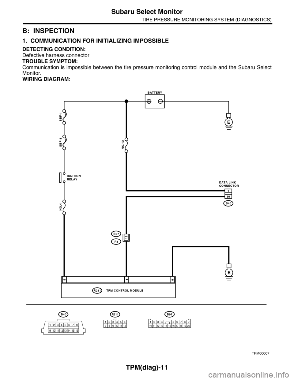
1. COMMUNICATION FOR INITIALIZING IMPOSSIBLE
DETECTING CONDITION:
Defective harness connector
TROUBLE SYMPTOM:
Communication is impossible between the tire pressure monitoring control module and the Subaru Select
Monitor.
WIRING DIAGRAM:
TPM00007
B40
12345678
910 11 12 13 14 15 16
SBF-1
SBF-8
NO.4
B40
R211
E
E
1
10
195
IGNITIONRELAY
BATTERY
DATA LINKCONNECTOR
NO.13
TPM CONTROL MODULE
R211
123456789101112
12B97
R1
B97
1234 567891011 1213 14 15 16 17 18 19 20
Page 1003 of 2453

VDC(diag)-11
Electrical Component Location
VEHICLE DYNAMICS CONTROL (VDC) (DIAGNOSTICS)
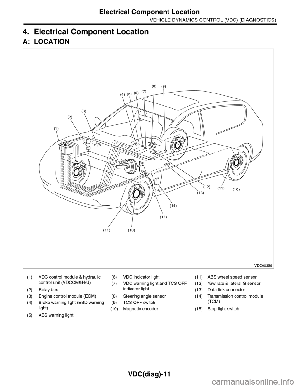
4. Electrical Component Location
A: LOCATION
(1) VDC control module & hydraulic
control unit (VDCCM&H/U)
(6) VDC indicator light (11) ABS wheel speed sensor
(7) VDC warning light and TCS OFF
indicator light
(12) Yaw rate & lateral G sensor
(2) Relay box (13) Data link connector
(3) Engine control module (ECM) (8) Steering angle sensor (14) Transmission control module
(TCM)(4) Brake warning light (EBD warning
light)
(9) TCS OFF switch
(10) Magnetic encoder (15) Stop light switch
(5) ABS warning light
(4)(5)(6)(7)
(8)
(1)
(2)
(3)
(15)
(14)
(12)
(13)
(11)(10)
(11)(10)
(9)
VDC00359
Page 1006 of 2453

VDC(diag)-14
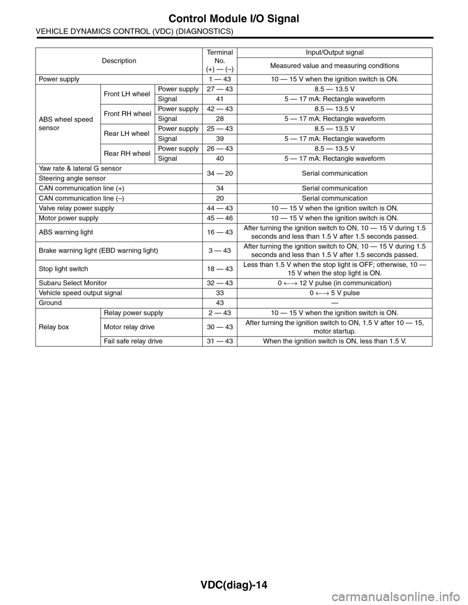
Control Module I/O Signal
VEHICLE DYNAMICS CONTROL (VDC) (DIAGNOSTICS)
Description
Te r m i n a l
No.
(+) — (–)
Input/Output signal
Measured value and measuring conditions
Pow er s up p ly 1 — 43 10 — 15 V w h e n t h e i gn i t io n sw it ch i s ON .
ABS wheel speed
sensor
Front LH wheelPowe r s u pp ly 27 — 4 3 8 . 5 — 1 3. 5 V
Signal 41 5 — 17 mA: Rectangle waveform
Front RH wheelPower supply 42 — 43 8.5 — 13.5 V
Signal 28 5 — 17 mA: Rectangle waveform
Rear LH wheelPower supply 25 — 43 8.5 — 13.5 V
Signal 39 5 — 17 mA: Rectangle waveform
Rear RH wheelPower supply 26 — 43 8.5 — 13.5 V
Signal 40 5 — 17 mA: Rectangle waveform
Ya w r a t e & l a t e r a l G s e n s o r34 — 20 Serial communicationSteering angle sensor
CAN communication line (+) 34 Serial communication
CAN communication line (–) 20 Serial communication
Valve relay power supply 44 — 43 10 — 15 V when the ignition switch is ON.
Motor power supply 45 — 46 10 — 15 V when the ignition switch is ON.
ABS warning light 16 — 43After turning the ignition switch to ON, 10 — 15 V during 1.5
seconds and less than 1.5 V after 1.5 seconds passed.
Brake warning light (EBD warning light) 3 — 43After turning the ignition switch to ON, 10 — 15 V during 1.5
seconds and less than 1.5 V after 1.5 seconds passed.
Stop light switch 18 — 43Less than 1.5 V when the stop light is OFF; otherwise, 10 —
15 V when the stop light is ON.
Subaru Select Monitor 32 — 43 0 ←→ 12 V pulse (in communication)
Ve h i c l e s p e e d o u t p u t s i g n a l 3 3 0 ←→ 5 V pulse
Ground 43 —
Relay box
Relay power supply 2 — 43 10 — 15 V when the ignition switch is ON.
Motor relay drive 30 — 43After turning the ignition switch to ON, 1.5 V after 10 — 15,
motor startup.
Fa i l s afe r e lay d r ive 31 — 4 3 W he n t h e i g ni t io n swit c h i s ON, l es s t ha n 1 . 5 V.