2009 SUBARU TRIBECA relay
[x] Cancel search: relayPage 1177 of 2453
EN(H6DO)(diag)-16
Engine Control Module (ECM) I/O Signal
ENGINE (DIAGNOSTICS)
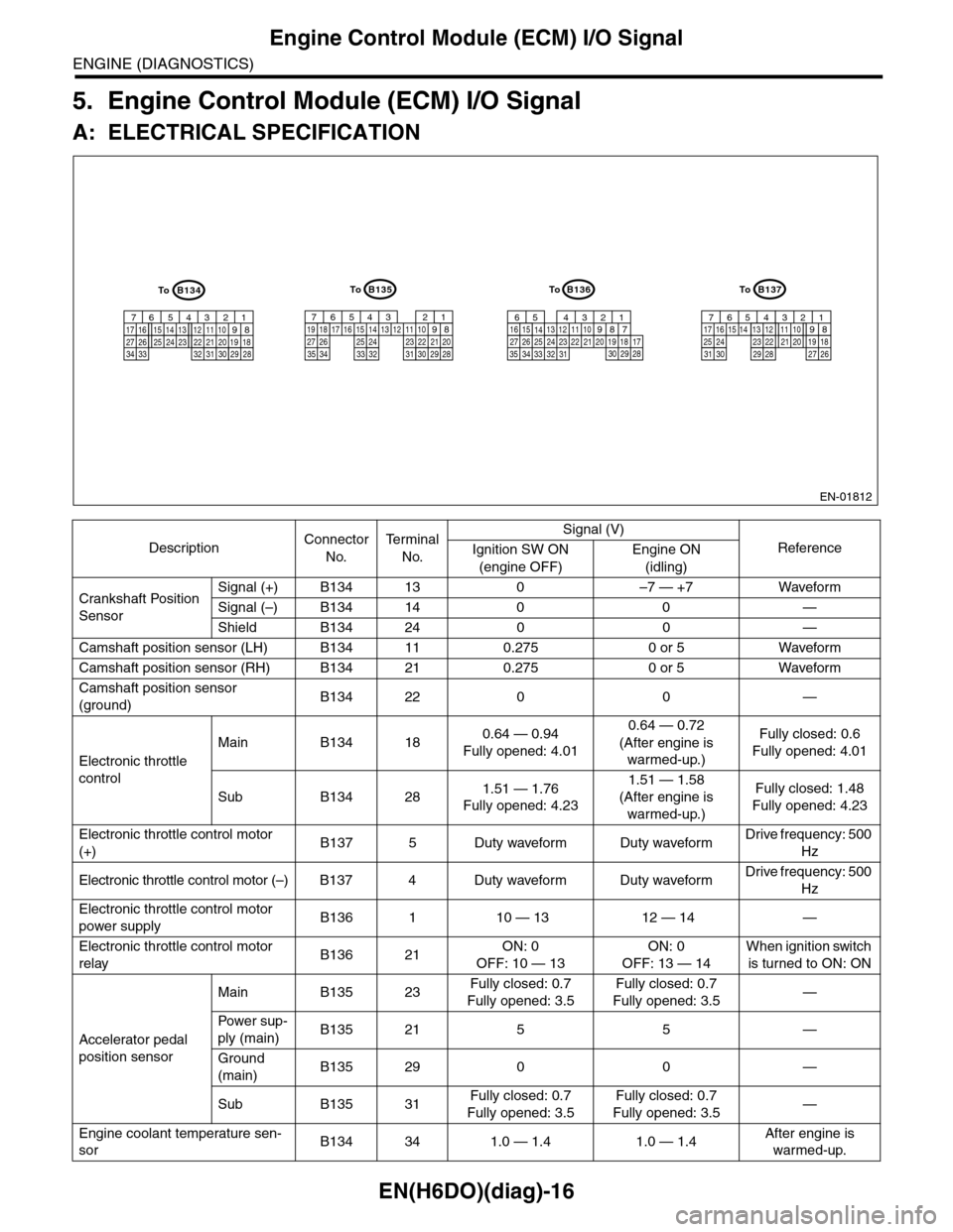
5. Engine Control Module (ECM) I/O Signal
A: ELECTRICAL SPECIFICATION
DescriptionConnector
No.
Te r m i n a l
No.
Signal (V)
ReferenceIgnition SW ON
(engine OFF)
Engine ON
(idling)
Crankshaft Position
Sensor
Signal (+) B134 13 0 –7 — +7 Waveform
Signal (–) B134 14 0 0 —
Shield B134 24 0 0 —
Camshaft position sensor (LH) B134 11 0.275 0 or 5 Waveform
Camshaft position sensor (RH) B134 21 0.275 0 or 5 Waveform
Camshaft position sensor
(ground)B134 22 0 0 —
Electronic throttle
control
Main B134 180.64 — 0.94
Fully opened: 4.01
0.64 — 0.72
(After engine is
warmed-up.)
Fully closed: 0.6
Fully opened: 4.01
Sub B134 281.51 — 1.76
Fully opened: 4.23
1.51 — 1.58
(After engine is
warmed-up.)
Fully closed: 1.48
Fully opened: 4.23
Electronic throttle control motor
(+)B137 5 Duty waveform Duty waveformDrive frequency: 500
Hz
Electronic throttle control motor (–) B137 4 Duty waveform Duty waveformDrive frequency: 500
Hz
Electronic throttle control motor
power supplyB136 1 10 — 13 12 — 14 —
Electronic throttle control motor
relayB136 21ON: 0
OFF: 10 — 13
ON: 0
OFF: 13 — 14
When ignition switch
is turned to ON: ON
Accelerator pedal
position sensor
Main B135 23Fully closed: 0.7
Fully opened: 3.5
Fully closed: 0.7
Fully opened: 3.5—
Powe r s up -
ply (main)B135 21 5 5 —
Ground
(main)B135 29 0 0 —
Sub B135 31Fully closed: 0.7
Fully opened: 3.5
Fully closed: 0.7
Fully opened: 3.5—
Engine coolant temperature sen-
sorB134 34 1.0 — 1.4 1.0 — 1.4After engine is
warmed-up.
EN-01812
B134
5678219431024 2223251112131415262728
1617181920213334 2932 3031
B136
5678219431024 2223251112131415262728
16171819202133342932303135
B135
5678219431024 2223251112131415262728
16171819202129303132333435
B137
5678219431022231112131415242526
1617181920212728293031
ToToToTo
Page 1178 of 2453
EN(H6DO)(diag)-17
Engine Control Module (ECM) I/O Signal
ENGINE (DIAGNOSTICS)
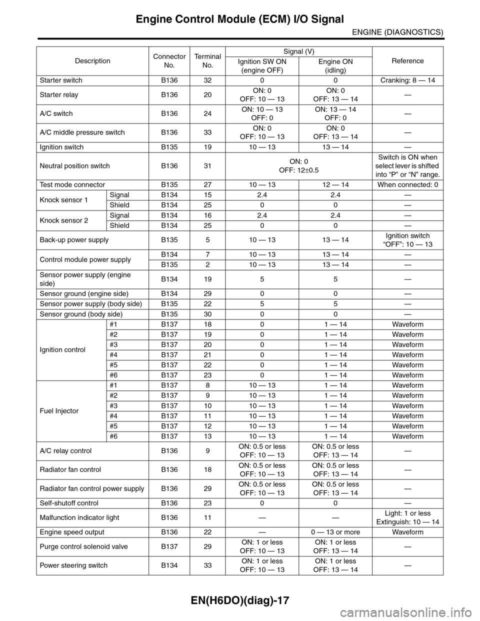
Starter switch B136 32 0 0 Cranking: 8 — 14
Starter relay B136 20ON: 0
OFF: 10 — 13
ON: 0
OFF: 13 — 14—
A/C switch B136 24ON: 10 — 13
OFF: 0
ON: 13 — 14
OFF: 0—
A/C middle pressure switch B136 33ON: 0
OFF: 10 — 13
ON: 0
OFF: 13 — 14—
Ignition switch B135 19 10 — 13 13 — 14 —
Neutral position switch B136 31ON: 0
OFF: 12±0.5
Switch is ON when
select lever is shifted
into “P” or “N” range.
Te s t m o d e c o n n e c t o r B 1 3 5 2 7 1 0 — 1 3 1 2 — 1 4 W h e n c o n n e c t e d : 0
Knock sensor 1Signal B134 15 2.4 2.4 —
Shield B134 25 0 0 —
Knock sensor 2Signal B134 16 2.4 2.4 —
Shield B134 25 0 0 —
Back-up power supply B135 5 10 — 13 13 — 14Ignition switch
“OFF”: 10 — 13
Control module power supplyB134 7 10 — 13 13 — 14 —
B135 2 10 — 13 13 — 14 —
Sensor power supply (engine
side)B134 19 5 5 —
Sensor ground (engine side) B134 29 0 0 —
Sensor power supply (body side) B135 22 5 5 —
Sensor ground (body side) B135 30 0 0 —
Ignition control
#1 B137 18 0 1 — 14 Waveform
#2 B137 19 0 1 — 14 Waveform
#3 B137 20 0 1 — 14 Waveform
#4 B137 21 0 1 — 14 Waveform
#5 B137 22 0 1 — 14 Waveform
#6 B137 23 0 1 — 14 Waveform
Fuel Injector
#1 B137 8 10 — 13 1 — 14 Waveform
#2 B137 9 10 — 13 1 — 14 Waveform
#3 B137 10 10 — 13 1 — 14 Waveform
#4 B137 11 10 — 13 1 — 14 Waveform
#5 B137 12 10 — 13 1 — 14 Waveform
#6 B137 13 10 — 13 1 — 14 Waveform
A/C relay control B136 9ON: 0.5 or less
OFF: 10 — 13
ON: 0.5 or less
OFF: 13 — 14—
Radiator fan control B136 18ON: 0.5 or less
OFF: 10 — 13
ON: 0.5 or less
OFF: 13 — 14—
Radiator fan control power supply B136 29ON: 0.5 or less
OFF: 10 — 13
ON: 0.5 or less
OFF: 13 — 14—
Self-shutoff control B136 23 0 0 —
Malfunction indicator light B136 11 — —Light: 1 or less
Extinguish: 10 — 14
Engine speed output B136 22 — 0 — 13 or more Waveform
Purge control solenoid valve B137 29ON: 1 or less
OFF: 10 — 13
ON: 1 or less
OFF: 13 — 14—
Pow er s te e r in g sw it c h B 1 3 4 33ON: 1 or less
OFF: 10 — 13
ON: 1 or less
OFF: 13 — 14—
DescriptionConnector
No.
Te r m i n a l
No.
Signal (V)
ReferenceIgnition SW ON
(engine OFF)
Engine ON
(idling)
Page 1189 of 2453
EN(H6DO)(diag)-28
Subaru Select Monitor
ENGINE (DIAGNOSTICS)
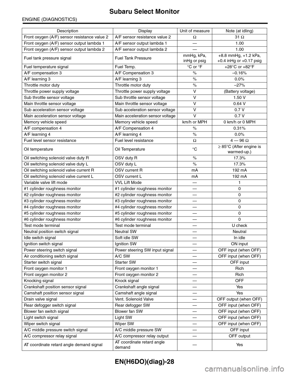
Fr o nt ox yg e n ( A / F) s en so r r es is t an ce val ue 2 A / F s en s or r e si st a nc e val u e 2Ω31 Ω
Fr o nt ox yg e n ( A / F) s en so r ou t p ut la m bd a 1 A / F s en s or o ut p ut l am bd a 1 — 1 . 00
Fr o nt ox yg e n ( A / F) s en so r ou t p ut la m bd a 2 A / F s en s or o ut p ut l am bd a 2 — 1 . 00
Fuel tank pressure signal Fuel Tank PressuremmHg, kPa,
inHg or psig
+8.8 mmHg, +1.2 kPa,
+0.4 inHg or +0.17 psig
Fuel temperature signal Fuel Temp. °C or °F +28°C or +82°F
A/F compensation 3 A/F Compensation 3 % –0.16%
A/F learning 3 A/F learning 3 % 0.0%
Throttle motor duty Throttle motor duty % –27%
Throttle power supply voltage Throttle power supply voltage V (Battery voltage)
Sub throttle sensor voltage Sub throttle sensor voltage V 1.50 V
Main throttle sensor voltage Main throttle sensor voltage V 0.64 V
Sub acceleration sensor voltage Sub acceleration sensor voltage V 0.7 V
Main acceleration sensor voltage Main acceleration sensor voltage V 0.7 V
Memory vehicle speed Memory vehicle speed km/h or MPH 0 km/h or 0 MPH
A/F compensation 4 A/F Compensation 4 % 0.31%
A/F learning 4 A/F learning 4 % 0.0%
Fuel level sensor resistance Fuel level resistanceΩ4 — 96 Ω
Oil temperature Oil Temperature °C≥ 85°C (After engine is
warmed-up.)
Oil switching solenoid valve duty R OSV duty R % 17.3%
Oil switching solenoid valve duty L OSV duty L % 17.3%
Oil switching solenoid valve current R OSV current R mA 192 mA
Oil switching solenoid valve current L OSV current L mA 192 mA
Va r i a b l e va l v e l i f t m o d e V V L L i f t M o d e — 1
#1 cylinder roughness monitor #1 cylinder roughness monitor — 0
#2 cylinder roughness monitor #2 cylinder roughness monitor — 0
#3 cylinder roughness monitor #3 cylinder roughness monitor — 0
#4 cylinder roughness monitor #4 cylinder roughness monitor — 0
#5 cylinder roughness monitor #5 cylinder roughness monitor — 0
#6 cylinder roughness monitor #6 cylinder roughness monitor — 0
Te s t m o d e t e r m i n a l Te s t m o d e t e r m i n a l — U c h e c k
Neutral position switch signal Neutral SW — Neutral
Idle switch signal Soft idle SW — In idle
Ignition switch signal Ignition SW — ON input
Pow er s te e r in g sw it c h s ig n al Powe r st ee r i ng S W i n pu t si gn a l — O FF i np u t ( w h e n OF F )
Air conditioning switch signal A/C SW — OFF input (when OFF)
Starter switch signal Starter SW — OFF input
Fr o nt ox yg e n mo n it o r 1 Fr o n t oxy ge n m on i to r 1 — Ri ch
Fr o nt ox yg e n mo n it o r 2 Fr o n t oxy ge n m on i to r 2 — Ri ch
Knocking signal Knock signal — OFF
Crankshaft position sensor signal Crankshaft angle signal — Yes
Camshaft position sensor signal Camshaft angle signal — Yes
Drain valve signal Vent. Solenoid Valve — OFF output (when OFF)
Rear defogger switch signal Rear defogger SW — OFF input (when OFF)
Blower fan switch signal Blower fan SW — OFF input (when OFF)
Light switch signal Light SW — OFF input (when OFF)
Wiper switch signal Wiper SW — OFF input (when OFF)
A/C middle pressure switch signal A/C middle pressure SW — OFF input
A/C compressor relay signal A/C compressor relay output — OFF output
AT c o o r d i n a t e r e t a r d a n g l e d e m a n d s i g n a lAT c o o r d i n a t e r e t a r d a n g l e
demand—Yes
Description Display Unit of measure Note (at idling)
Page 1190 of 2453
![SUBARU TRIBECA 2009 1.G Service Workshop Manual EN(H6DO)(diag)-29
Subaru Select Monitor
ENGINE (DIAGNOSTICS)
5. READ CURRENT DATA FOR ENGINE (OBD MODE)
1) On the «Main Menu» display screen, select the {Each System Check} and press the [YES] key.
SUBARU TRIBECA 2009 1.G Service Workshop Manual EN(H6DO)(diag)-29
Subaru Select Monitor
ENGINE (DIAGNOSTICS)
5. READ CURRENT DATA FOR ENGINE (OBD MODE)
1) On the «Main Menu» display screen, select the {Each System Check} and press the [YES] key.](/manual-img/17/7322/w960_7322-1189.png)
EN(H6DO)(diag)-29
Subaru Select Monitor
ENGINE (DIAGNOSTICS)
5. READ CURRENT DATA FOR ENGINE (OBD MODE)
1) On the «Main Menu» display screen, select the {Each System Check} and press the [YES] key.
2) On the «System Selection Menu» display screen, select the {Engine} and press the [YES] key.
3) Press the [YES] key after the information of engine type has been displayed.
4) On the «Engine Diagnosis» display screen, select the {OBD System} and press the [YES] key.
5) On the «OBD Menu» display screen, select the {Current Data Display/Save}, and then press the [YES]
key.
6) On the «Data Display Menu» screen, select the {Data Display} and press the [YES] key.
7) Using the scroll key, scroll the display screen up or down until the desired data is shown.
•A list of the support data is shown in the following table.
AT c o o r d i n a t e f u e l c u t d e m a n d s i g n a l AT c o o r d i n a t e f u e l c u t d e m a n d — O F F
Ve h i c l e d y n a m i c s c o n t r o l ( V D C ) t o r q u e d o w n
prohibition outputBan of Torque Down — Permission
Ve h i c l e d y n a m i c s c o n t r o l ( V D C ) t o r q u e d o w n
demandVDC torque down demand — OFF
AT c o o r d i n a t e p e r m i s s i o n s i g n a l AT c o o r d i n a t e p e r m i s s i o n s i g n a l — P e r m i s s i o n
Electronic throttle control motor relay signal ETC motor relay — ON
Stop light switch signal Stop Light Switch — OFF
SET/COAST switch signal SET/COAST SW — OFF
RESUME/ACCEL switch signal RESUME/ACCEL SW — OFF
Brake switch signal Brake SW — OFF
Main switch signal Main SW — OFF
Body integrated unit data reception Body Int. Unit Data — Yes
Body integlated unit counter update Body Int. Unit Count — Yes
Cruise control cancel switch signal CC Cancel SW — OFF
Va r i a b l e v a l v e l i f t d i a g n o s i s o i l p r e s s u r e sw i t c h
signal 1Oil Temperature SW1 — ON
Va r i a b l e v a l v e l i f t d i a g n o s i s o i l p r e s s u r e sw i t c h
signal 2Oil Temperature SW2 — ON
Description Display Unit of measure
Number of diagnosis code Number of Diag. Codes: 0
Condition of malfunction indicator light MI (MIL) ON or OFF
Monitoring test of misfire Misfire monitoring Finish
Monitoring test of fuel system Fuel system monitoring Finish
Monitoring test of comprehensive component Component monitoring Finish
Te s t o f c a t a l y s t C a t a l y s t D i a g n o s i s F i n i s h o r i n c o m p l e t e
Te s t o f h e a t i n g - t y p e c a t a l y s t H e a t e d c a t a l y s t N o
Te s t o f e v a p o r a t i v e e m i s s i o n p u r g e c o n t r o l s y s t e m E v a p o r a t i v e p u r g e s y s t e m F i n i s h o r i n c o m p l e t e
Te s t o f s e c o n d a r y a i r s y s t e m S e c o n d a r y a i r s y s t e m N o
Te s t o f a i r c o n d i t i o n i n g s y s t e m r e f r i g e r a n t A / C s y s t e m r e f r i g e r a n t N o
Te s t o f o x y g e n s e n s o r O x y g e n s e n o r F i n i s h o r i n c o m p l e t e
Te s t o f o x y g e n s e n s o r h e a t e r O x y g e n s e n s o r h e a t e r F i n i s h
Te s t o f E G R s y s t e m E G R s y s t e m N o s u p p o r t
A/F control #1 Fuel system for Bank 1 OPEN early period
A/F control #2 Fuel system for Bank 2 OPEN early period
Calculated load valve Calculated load valve %
Engine coolant temperature Coolant Temp. °C
A/F compensation #1 Short term fuel trim B1 %
A/F learning #1 Long term fuel trim B1 %
A/F compensation #2 Short term fuel trim #2 %
A/F learning #2 Long term fuel trim B2 %
Description Display Unit of measure Note (at idling)
Page 1193 of 2453
![SUBARU TRIBECA 2009 1.G Service Workshop Manual EN(H6DO)(diag)-32
Subaru Select Monitor
ENGINE (DIAGNOSTICS)
7. LED OPERATION MODE FOR ENGINE
1) On the «Main Menu» display screen, select the {Each System Check} and press the [YES] key.
2) On the SUBARU TRIBECA 2009 1.G Service Workshop Manual EN(H6DO)(diag)-32
Subaru Select Monitor
ENGINE (DIAGNOSTICS)
7. LED OPERATION MODE FOR ENGINE
1) On the «Main Menu» display screen, select the {Each System Check} and press the [YES] key.
2) On the](/manual-img/17/7322/w960_7322-1192.png)
EN(H6DO)(diag)-32
Subaru Select Monitor
ENGINE (DIAGNOSTICS)
7. LED OPERATION MODE FOR ENGINE
1) On the «Main Menu» display screen, select the {Each System Check} and press the [YES] key.
2) On the «System Selection Menu» display screen, select the {Engine} and press the [YES] key.
3) Press the [YES] key after the information of engine type has been displayed.
4) On the «Engine Diagnosis» display screen, select the {Current Data Display/Save}, and then press the
[YES] key.
5) On the «Data Display» screen, select the {Data LED Display} and press the [YES] key.
6) Using the scroll key, scroll the display screen up or down until the desired data is shown.
•A list of the support data is shown in the following table.
NOTE:
For detailed operation procedure, refer to the “SUBARU SELECT MONITOR OPERATION MANUAL”.
Description Display Message When LED “ON” required
Te s t m o d e s i g n a l Te s t m o d e t e r m i n a l D c h e c k / U c h e c k D c h e c k
Neutral position switch signal Neutral SW Neutral/Other than neutral Neutral
Idle switch signal Soft idle SW Idle/Other than idle In idle
Ignition switch signal Ignition SW ON Input/OFF Input ON input
Pow er s te e r in g sw it c h s ig n al Pow er s te e r in g S W ON I np u t/ O FF I np u t ON i np ut
Air conditioning switch signal A/C SW ON Input/OFF Input ON input
Starter switch signal Starter SW ON Input/OFF Input ON input
Fr o nt ox yg e n mo n it o r 1 Ft O 2 mo n it o r 1 Le a n/ Ri ch Ric h
Fr o nt ox yg e n mo n it o r 2 Ft O 2 mo n it o r 2 Le a n/ Ri ch Ric h
Knocking signal Knock signal Yes/No Yes
Crankshaft position sensor signal Crankshaft angle signal Yes/No Yes
Camshaft position sensor signal Camshaft angle signal Yes/No Yes
Rear defogger switch signal Rear defogger SW ON Input/OFF Input ON input
Blower fan switch signal Blower fan SW ON Input/OFF Input ON input
Light switch signal Light SW ON Input/OFF Input ON input
Wiper switch signal Wiper SW ON Input/OFF Input ON input
A/C middle pressure switch signal A/C middle pressure SW ON Input/OFF Input ON input
Air conditioner compressor relay sig-
nalCompressor relay ON output/OFF output ON output
Drain valve signal Vent. Solenoid Valve ON or OFF When drain valve is ON.
AT r e t a r d a n g l e d e m a n d s i g n a l AT r e t a r d a n g l e d e m a n d Ye s / N o Ye s
AT f u e l c u t s i g n a l AT f u e l c u t Ye s / N o Ye s
VDC torque down prohibition output Torque down output ON/OFF Prohibition
VDC torque down demand Torque down demand Yes/No Yes
AT c o o r d i n a t e p e r m i s s i o n s i g n a lAT c o o r d i n a t e p e r m i s s i o n
signalON/OFF Permission
Electronic throttle control motor relay
signalETC motor relay ON/OFF ON
Stop light switch signal Stop SW ON Input/OFF Input ON input
SET/COAST switch signal SET/CST SW ON Input/OFF Input ON input
RESUME/ACCEL switch signal RES/ACC SW ON Input/OFF Input ON input
Brake switch signal Brake SW ON Input/OFF Input ON input
Main switch signal Main SW ON Input/OFF Input ON input
Body integrated unit data reception Body Int. Unit Data Yes/No Yes
Body integrated unit counter update Body Int. Unit Count Yes/No Yes
Cruise control cancel switch signal CC Cancel SW ON Input/OFF Input ON input
Va r i a b l e va l v e l i f t d i a g n o s i s o i l p r e s -
sure switch signal 1Oil Temperature SW1 ON/OFF ON
Va r i a b l e va l v e l i f t d i a g n o s i s o i l p r e s -
sure switch signal 2Oil Temperature SW2 ON/OFF ON
Page 1208 of 2453
![SUBARU TRIBECA 2009 1.G Service Workshop Manual EN(H6DO)(diag)-47
Compulsory Valve Operation Check Mode
ENGINE (DIAGNOSTICS)
13) Pressing the [NO] key completes the compul-
sory valve operation check mode. The display will
then return to SUBARU TRIBECA 2009 1.G Service Workshop Manual EN(H6DO)(diag)-47
Compulsory Valve Operation Check Mode
ENGINE (DIAGNOSTICS)
13) Pressing the [NO] key completes the compul-
sory valve operation check mode. The display will
then return to](/manual-img/17/7322/w960_7322-1207.png)
EN(H6DO)(diag)-47
Compulsory Valve Operation Check Mode
ENGINE (DIAGNOSTICS)
13) Pressing the [NO] key completes the compul-
sory valve operation check mode. The display will
then return to the «Actuator ON/OFF Operation»
screen.
•A list of the support data is shown in the following
table.
NOTE:
•The following parts will be displayed but not
functional.
•For detailed operation procedure, refer to the
“SUBARU SELECT MONITOR OPERATION
MANUAL”.
Description Display
Compulsory fuel pump relay oper-
ation checkFuel Pump
Compulsory radiator fan relay
operation checkRadiator Fan Relay
Compulsory air conditioning relay
operation checkA/C Compressor Relay
Compulsory purge control sole-
noid valve operation checkCPC Solenoid
Compulsory drain valve operation
checkVe n t C o n t r o l S o l e n o i d
Display
EGR Solenoid
ASV Solenoid
FICD Solenoid
Pressure Switching Solenoid 1
Pressure Switching Solenoid 2
Wa st e g at e Con t r ol S ol e no i d
AAI Solenoid
Exhaust Bypass Valve Control Permit Flag
PCV Solenoid
Fuel tank sensor control valve
Page 1219 of 2453
EN(H6DO)(diag)-58
Diagnostics for Engine Starting Failure
ENGINE (DIAGNOSTICS)
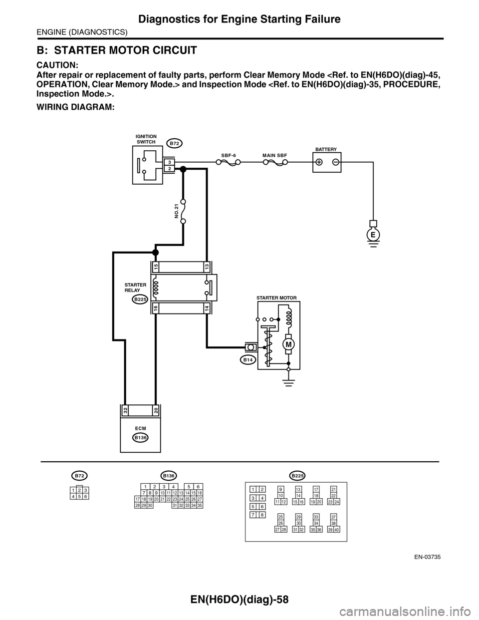
B: STARTER MOTOR CIRCUIT
CAUTION:
After repair or replacement of faulty parts, perform Clear Memory Mode
WIRING DIAGRAM:
EN-03735
3220
NO.21
B225
MAIN SBFSBF-6
E
1513
1614
ECM
B136
B72
B14
M
23
B72B225
101112
131415 16
17181920
21222324
25262728
293031 32
333435 36 39 40
3738
129
34
56
78
134562
BATTERY
IGNITIONSWITCH
STARTERRELAYSTARTER MOTOR
B136
16101112131415252430
9871718192028212223293231
123456
2726333435
Page 1220 of 2453
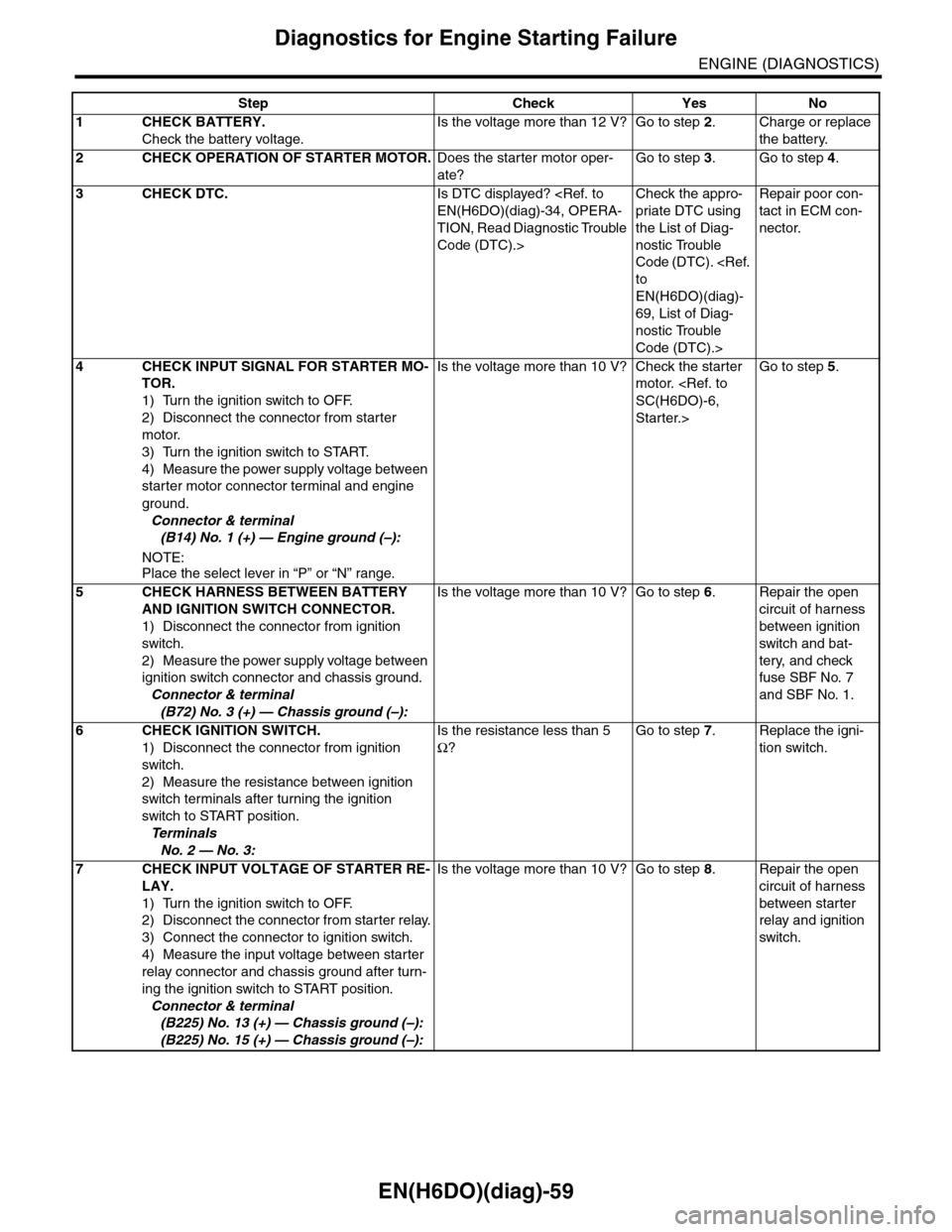
EN(H6DO)(diag)-59
Diagnostics for Engine Starting Failure
ENGINE (DIAGNOSTICS)
Step Check Yes No
1CHECK BATTERY.
Check the battery voltage.
Is the voltage more than 12 V? Go to step 2.Charge or replace
the battery.
2CHECK OPERATION OF STARTER MOTOR.Does the starter motor oper-
ate?
Go to step 3.Go to step 4.
3CHECK DTC.Is DTC displayed?
TION, Read Diagnostic Trouble
Code (DTC).>
Check the appro-
priate DTC using
the List of Diag-
nostic Trouble
Code (DTC).
EN(H6DO)(diag)-
69, List of Diag-
nostic Trouble
Code (DTC).>
Repair poor con-
tact in ECM con-
nector.
4CHECK INPUT SIGNAL FOR STARTER MO-
TOR.
1) Turn the ignition switch to OFF.
2) Disconnect the connector from starter
motor.
3) Turn the ignition switch to START.
4) Measure the power supply voltage between
starter motor connector terminal and engine
ground.
Connector & terminal
(B14) No. 1 (+) — Engine ground (–):
NOTE:Place the select lever in “P” or “N” range.
Is the voltage more than 10 V? Check the starter
motor.
Starter.>
Go to step 5.
5CHECK HARNESS BETWEEN BATTERY
AND IGNITION SWITCH CONNECTOR.
1) Disconnect the connector from ignition
switch.
2) Measure the power supply voltage between
ignition switch connector and chassis ground.
Connector & terminal
(B72) No. 3 (+) — Chassis ground (–):
Is the voltage more than 10 V? Go to step 6.Repair the open
circuit of harness
between ignition
switch and bat-
tery, and check
fuse SBF No. 7
and SBF No. 1.
6CHECK IGNITION SWITCH.
1) Disconnect the connector from ignition
switch.
2) Measure the resistance between ignition
switch terminals after turning the ignition
switch to START position.
Te r m i n a l s
No. 2 — No. 3:
Is the resistance less than 5
Ω?
Go to step 7.Replace the igni-
tion switch.
7CHECK INPUT VOLTAGE OF STARTER RE-
LAY.
1) Turn the ignition switch to OFF.
2) Disconnect the connector from starter relay.
3) Connect the connector to ignition switch.
4) Measure the input voltage between starter
relay connector and chassis ground after turn-
ing the ignition switch to START position.
Connector & terminal
(B225) No. 13 (+) — Chassis ground (–):
(B225) No. 15 (+) — Chassis ground (–):
Is the voltage more than 10 V? Go to step 8.Repair the open
circuit of harness
between starter
relay and ignition
switch.