2009 SUBARU TRIBECA relay
[x] Cancel search: relayPage 1007 of 2453
VDC(diag)-15
Control Module I/O Signal
VEHICLE DYNAMICS CONTROL (VDC) (DIAGNOSTICS)
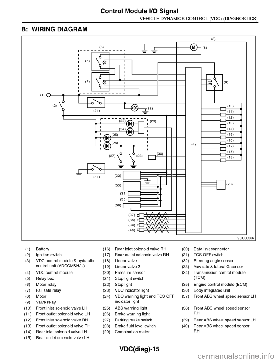
B: WIRING DIAGRAM
(1) Battery (16) Rear inlet solenoid valve RH (30) Data link connector
(2) Ignition switch (17) Rear outlet solenoid valve RH (31) TCS OFF switch
(3) VDC control module & hydraulic
control unit (VDCCM&H/U)
(18) Linear valve 1 (32) Steering angle sensor
(19) Linear valve 2 (33) Yaw rate & lateral G sensor
(4) VDC control module (20) Pressure sensor (34)
Tr a n s m i s s i o n c o n t r o l m o d u l e
(TCM)(5) Relay box (21) Stop light switch
(6) Motor relay (22) Stop light (35) Engine control module (ECM)
(7) Fail safe relay (23) VDC indicator light (36) Body integrated unit
(8) Motor (24) VDC warning light and TCS OFF
indicator light
(37)
Fr o nt A B S w he e l sp ee d se n so r L H
(9) Valve relay
(10) Front inlet solenoid valve LH (25) ABS warning light (38)
Fr o nt A B S w he e l sp e ed se n so r
RH(11) Front outlet solenoid valve LH (26) Brake warning light
(12) Front inlet solenoid valve RH (27) Parking brake switch (39) Rear ABS wheel speed sensor LH
(13) Front outlet solenoid valve RH (28) Brake fluid level switch (40) Rear ABS wheel speed sensor
RH(14) Rear inlet solenoid valve LH (29) Combination meter
(15) Rear outlet solenoid valve LH
VDC00366
M
(17)(4)(16)
(19)
(20)
(18)
(38)
(37)
(32)
(33)
(36)
(34)
(35)
(40)
(39)
(15)
(14)
(13)
(12)
(7)
(22)(21)
(31)
(23)(29)
(24)
(25)
(26)
(27) (28)(30)
(1)
(2)
(6)
(11)
(10)
(9)
(8)
(3)
(5)
Page 1009 of 2453
![SUBARU TRIBECA 2009 1.G Service Workshop Manual VDC(diag)-17
Subaru Select Monitor
VEHICLE DYNAMICS CONTROL (VDC) (DIAGNOSTICS)
2. READ CURRENT DATA
1) On the «Main Menu» display screen, select the {Each System Check} and press the [YES] key.
2) SUBARU TRIBECA 2009 1.G Service Workshop Manual VDC(diag)-17
Subaru Select Monitor
VEHICLE DYNAMICS CONTROL (VDC) (DIAGNOSTICS)
2. READ CURRENT DATA
1) On the «Main Menu» display screen, select the {Each System Check} and press the [YES] key.
2)](/manual-img/17/7322/w960_7322-1008.png)
VDC(diag)-17
Subaru Select Monitor
VEHICLE DYNAMICS CONTROL (VDC) (DIAGNOSTICS)
2. READ CURRENT DATA
1) On the «Main Menu» display screen, select the {Each System Check} and press the [YES] key.
2) On the «System Selection Menu» display screen, select the {Brake Control} and press the [YES] key.
3) Press the [YES] key after {VDC AWD AT} is displayed.
4) On the «Brake Control Diagnosis» display screen, select the {Current Data Display/Save}, and then press
the [YES] key.
5) On the «Display Menu» screen, select the data display method and press the [YES] key.
6) Using a scroll key, scroll the display screen up or down until necessary data is shown.
•A list of the support data is shown in the following table.
NOTE:
For details concerning operation procedure, refer to the “SUBARU SELECT MONITOR OPERATION MAN-
UAL”.
Display Contents to be monitored Unit of measure
FR Wheel SpeedWheel speed detected by front ABS wheel speed sensor RH is dis-
played.km/h or MPH
FL Wheel SpeedWheel speed detected by front ABS wheel speed sensor LH is dis-
played.km/h or MPH
RR Wheel SpeedWheel speed detected by rear ABS wheel speed sensor RH is dis-
played.km/h or MPH
RL Wheel SpeedWheel speed detected by rear ABS wheel speed sensor LH is dis-
played.km/h or MPH
Fr o nt / Re ar G S e ns o r Ve h ic le f r on t / re a r ac ce le ra t io n d e te c te d by G se n so r is d i sp layed .m/s2
Lateral G Sensor Vehicle lateral acceleration detected by G sensor is displayed.m/s2
IG power supply voltage Voltage supplied to VDCCM&H/U is displayed. V
Steering Angle Sensor Steering angle detected by steering angle sensor is displayed. deg
Ya w R a t e S e n s o r V e h i c l e a n g u l a r s p e e d d e t e c t e d b y y a w r a t e s e n s o r i s d i s p l a y e d . d e g / s
Pressure Sensor Brake fluid pressure detected by pressure sensor is displayed. bar
ABS Control Flag ABS control condition is displayed. ON or OFF
EBD Control Flag EBD control condition is displayed. ON or OFF
Brake Switch Brake ON/OFF is displayed. ON or OFF
ABS Warning Light ON operation of the ABS warning light is displayed. ON or OFF
EBD Warning Light ON operation of the EBD warning light is displayed. ON or OFF
Motor Relay Signal Motor relay operation signal is displayed. ON or OFF
Motor Relay Monitor Motor relay monitor signal is displayed. ON or OFF
TCS Control Flag TCS control condition is displayed. ON or OFF
Va l ve R e l ay S i g n a l Va l v e r e l ay o p e r a t i o n s i g n a l i s d i s p l ay e d . O N o r O F F
VDC Control Flag VDC control condition is displayed. ON or OFF
VDC Warning Light ON operation of the VDC warning light is displayed. ON or OFF
OFF Light ON/OFF condition of TCS OFF indicator light is displayed. ON or OFF
E/G Control Prohibited Flag Engine control command signal is displayed. 1 or 0
OFF Switch Signal Operation condition of TCS OFF switch is displayed. ON or OFF
Motor Fail Safe Relay Drive
SignalMotor fail safe relay drive signal is displayed. ON or OFF
Page 1027 of 2453
VDC(diag)-35
List of Diagnostic Trouble Code (DTC)
VEHICLE DYNAMICS CONTROL (VDC) (DIAGNOSTICS)
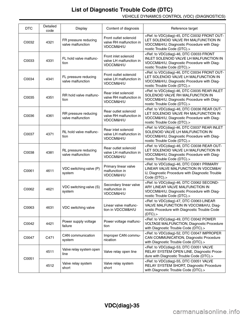
C0032 4321FR pressure reducing
valve malfunction
Fr o nt o ut l et s ol en o id
valve RH malfunction in
VDCCM&H/U
VDCCM&H/U, Diagnostic Procedure with Diag-
nostic Trouble Code (DTC).>
C0033 4331FL hold valve malfunc-
tion
Fr o nt i nl e t s ol e no i d
valve LH malfunction in
VDCCM&H/U
VDCCM&H/U, Diagnostic Procedure with Diag-
nostic Trouble Code (DTC).>
C0034 4341FL pressure reducing
valve malfunction
Fr o nt o ut l et s ol en o id
valve LH malfunction in
VDCCM&H/U
VDCCM&H/U, Diagnostic Procedure with Diag-
nostic Trouble Code (DTC).>
C0035 4351RR hold valve malfunc-
tion
Rear inlet solenoid
valve RH malfunction in
VDCCM&H/U
VDCCM&H/U, Diagnostic Procedure with Diag-
nostic Trouble Code (DTC).>
C0036 4361RR pressure reducing
valve malfunction
Rear outlet solenoid
valve RH malfunction in
VDCCM&H/U
VDCCM&H/U, Diagnostic Procedure with Diag-
nostic Trouble Code (DTC).>
C0037 4371RL hold valve malfunc-
tion
Rear inlet solenoid
valve LH malfunction in
VDCCM&H/U
VDCCM&H/U, Diagnostic Procedure with Diag-
nostic Trouble Code (DTC).>
C0038 4381RL pressure reducing
valve malfunction
Rear outlet solenoid
valve LH malfunction in
VDCCM&H/U
VDCCM&H/U, Diagnostic Procedure with Diag-
nostic Trouble Code (DTC).>
C0061 4611VDC switching valve (P)
system
Primary linear valve
malfunction in
VDCCM&H/U
U, D iagnostic Procedure with Diagnostic Trouble
Code (DTC).>
C0062 4621VDC switching valve (S)
system
Secondary linear valve
malfunction in
VDCCM&H/U
VDCCM&H/U, Diagnostic Procedure with Diag-
nostic Trouble Code (DTC).>
C0063 4631 VDC switching valveLinear valve malfunc-
tion in VDCCM&H/U
nostic Procedure with Diagnostic Trouble Code
(DTC).>
C0042 4421Pow er s up p ly vo lt a ge
failure
Powe r vo lt a ge ma lf u nc -
tion
with Diagnostic Trouble Code (DTC).>
C0047 C471CAN communication
system
Improper CAN commu-
nication
with Diagnostic Trouble Code (DTC).>
C0051
4511Va l ve r e l a y s y s t e m o p e n
lineVa l ve r e l ay o p e n l i n e
dure with Diagnostic Trouble Code (DTC).>
4512Va l ve r e l ay s y s t e m
short
Va l ve r e l ay s y s t e m
short
with Diagnostic Trouble Code (DTC).>
DTCDetailed
codeDisplay Content of diagnosis Reference target
Page 1028 of 2453
VDC(diag)-36
List of Diagnostic Trouble Code (DTC)
VEHICLE DYNAMICS CONTROL (VDC) (DIAGNOSTICS)
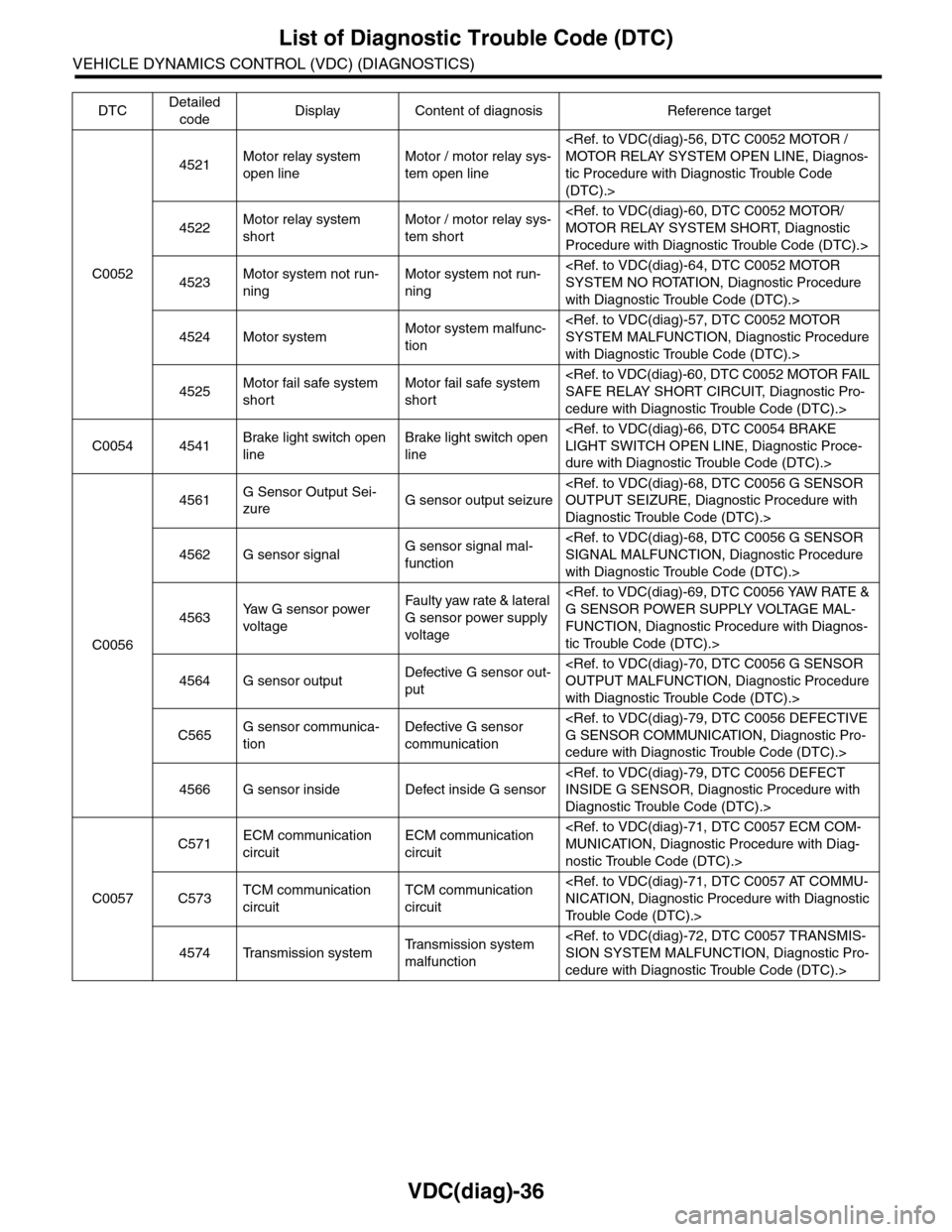
C0052
4521Motor relay system
open line
Motor / motor relay sys-
tem open line
tic Procedure with Diagnostic Trouble Code
(DTC).>
4522Motor relay system
short
Motor / motor relay sys-
tem short
Procedure with Diagnostic Trouble Code (DTC).>
4523Motor system not run-
ning
Motor system not run-
ning
with Diagnostic Trouble Code (DTC).>
4524 Motor systemMotor system malfunc-
tion
with Diagnostic Trouble Code (DTC).>
4525Motor fail safe system
short
Motor fail safe system
short
cedure with Diagnostic Trouble Code (DTC).>
C0054 4541Brake light switch open
line
Brake light switch open
line
dure with Diagnostic Trouble Code (DTC).>
C0056
4561G Sensor Output Sei-
zureG sensor output seizure
Diagnostic Trouble Code (DTC).>
4562 G sensor signalG sensor signal mal-
function
with Diagnostic Trouble Code (DTC).>
4563Ya w G s e n s o r p o w e r
voltage
Fau l t y yaw ra te & la t era l
G sensor power supply
voltage
FUNCTION, Diagnostic Procedure with Diagnos-
tic Trouble Code (DTC).>
4564 G sensor outputDefective G sensor out-
put
with Diagnostic Trouble Code (DTC).>
C565G sensor communica-
tion
Defective G sensor
communication
cedure with Diagnostic Trouble Code (DTC).>
4566 G sensor inside Defect inside G sensor
Diagnostic Trouble Code (DTC).>
C0057
C571ECM communication
circuit
ECM communication
circuit
nostic Trouble Code (DTC).>
C573TCM communication
circuit
TCM communication
circuit
Tr o u b l e C o d e ( D T C ) . >
4574 Transmission systemTr a n s m i s s i o n s y s t e m
malfunction
cedure with Diagnostic Trouble Code (DTC).>
DTCDetailed
codeDisplay Content of diagnosis Reference target
Page 1045 of 2453
VDC(diag)-53
Diagnostic Procedure with Diagnostic Trouble Code (DTC)
VEHICLE DYNAMICS CONTROL (VDC) (DIAGNOSTICS)
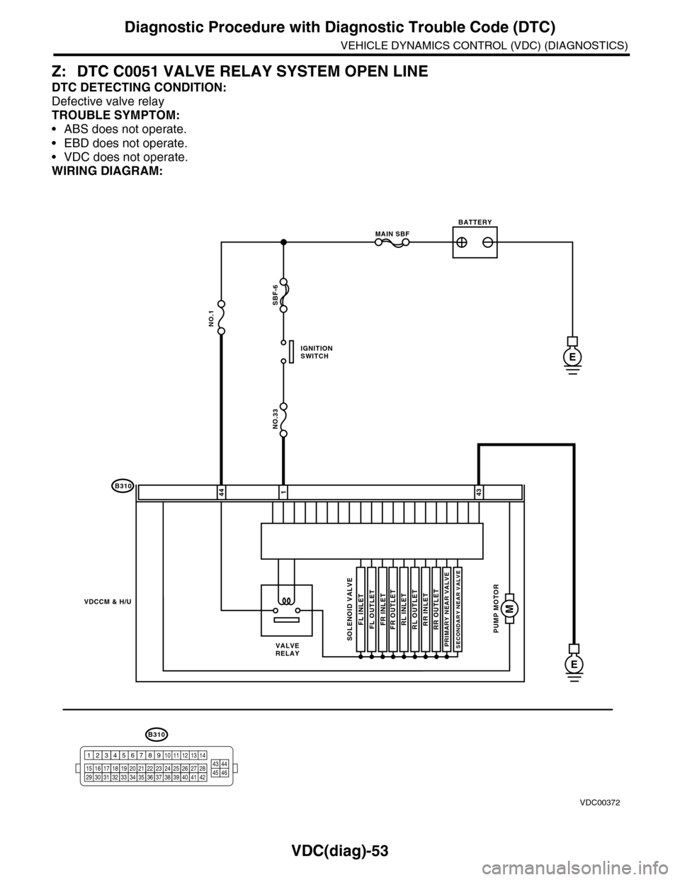
Z: DTC C0051 VALVE RELAY SYSTEM OPEN LINE
DTC DETECTING CONDITION:
Defective valve relay
TROUBLE SYMPTOM:
•ABS does not operate.
•EBD does not operate.
•VDC does not operate.
WIRING DIAGRAM:
B310
E
4443
VDCCM & H/U
1
PUMP MOTOR
M
FL INLET
MAIN SBF
SBF-6
NO.1
NO.33
E
BATTERY
IGNITIONSWITCH
SOLENOID VALVE
FR INLETRL INLETRR INLETFL OUTLETFR OUTLETRL OUTLETRR OUTLET
PRIMARY NEAR VALVESECONDARY NEAR VALVEVALVERELAY
VDC00372
B310
1234
1516171819202122232425262728293031323334353637383940414245464344568910 11 12 13 147
Page 1047 of 2453
VDC(diag)-55
Diagnostic Procedure with Diagnostic Trouble Code (DTC)
VEHICLE DYNAMICS CONTROL (VDC) (DIAGNOSTICS)
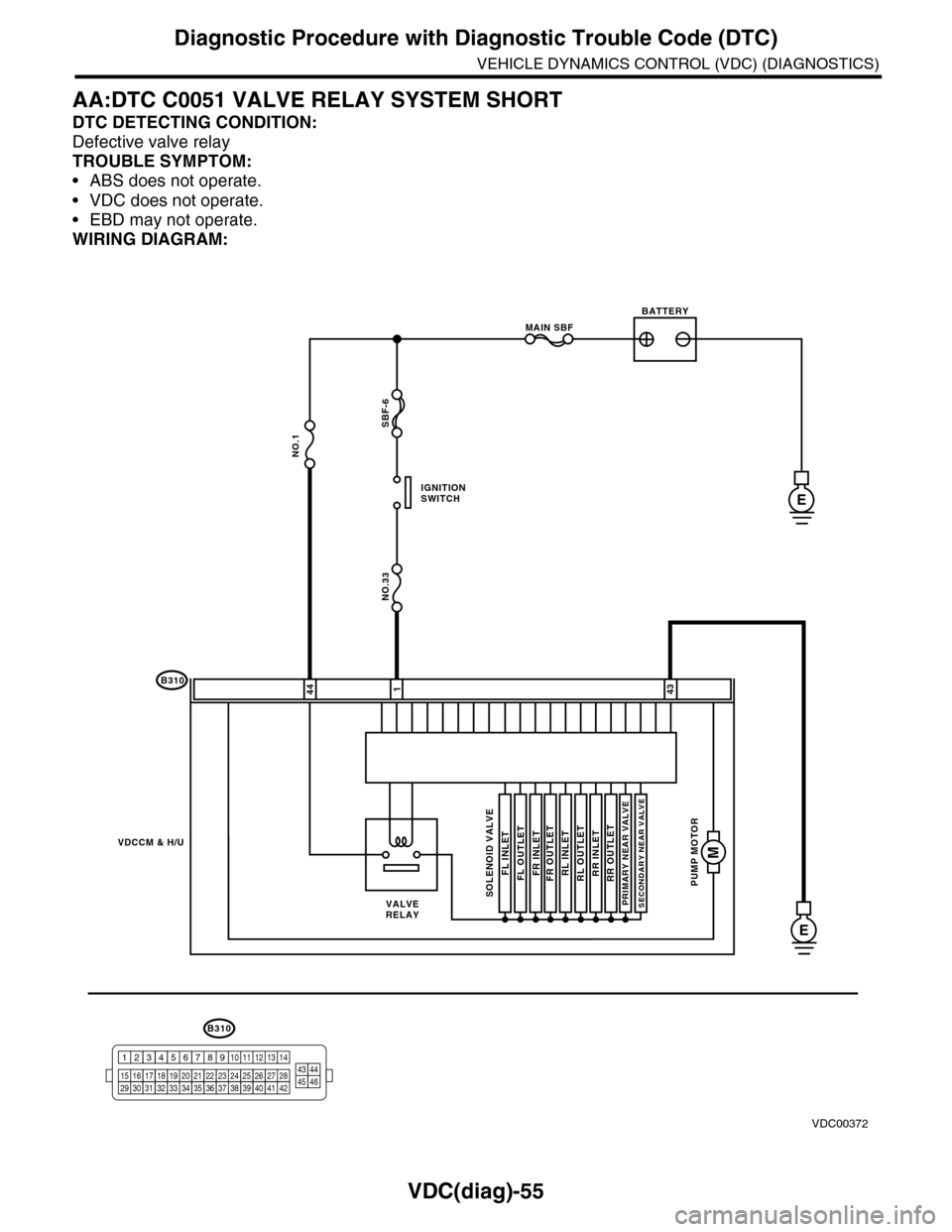
AA:DTC C0051 VALVE RELAY SYSTEM SHORT
DTC DETECTING CONDITION:
Defective valve relay
TROUBLE SYMPTOM:
•ABS does not operate.
•VDC does not operate.
•EBD may not operate.
WIRING DIAGRAM:
B310
E
4443
VDCCM & H/U
1
PUMP MOTOR
M
FL INLET
MAIN SBF
SBF-6
NO.1
NO.33
E
BATTERY
IGNITIONSWITCH
SOLENOID VALVE
FR INLETRL INLETRR INLETFL OUTLETFR OUTLETRL OUTLETRR OUTLET
PRIMARY NEAR VALVESECONDARY NEAR VALVEVALVERELAY
VDC00372
B310
1234
1516171819202122232425262728293031323334353637383940414245464344568910 11 12 13 147
Page 1048 of 2453
VDC(diag)-56
Diagnostic Procedure with Diagnostic Trouble Code (DTC)
VEHICLE DYNAMICS CONTROL (VDC) (DIAGNOSTICS)
AB:DTC C0052 MOTOR / MOTOR RELAY SYSTEM OPEN LINE
NOTE:
For the diagnostic procedure, refer to DTC C0052 “MOTOR SYSTEM MALFUNCTION.”
(DTC).>
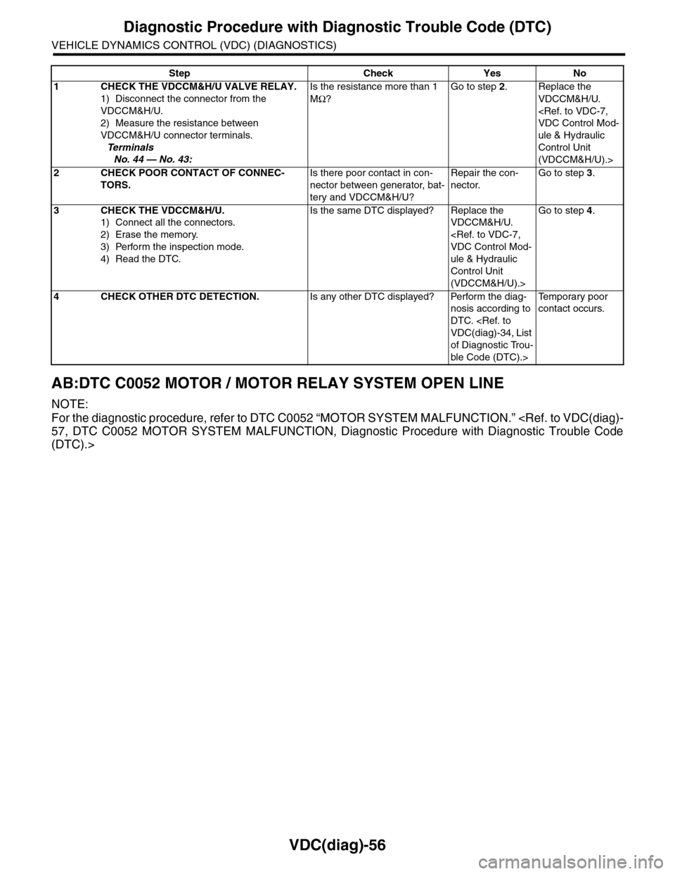
Step Check Yes No
1CHECK THE VDCCM&H/U VALVE RELAY.
1) Disconnect the connector from the
VDCCM&H/U.
2) Measure the resistance between
VDCCM&H/U connector terminals.
Te r m i n a l s
No. 44 — No. 43:
Is the resistance more than 1
MΩ?
Go to step 2.Replace the
VDCCM&H/U.
ule & Hydraulic
Control Unit
(VDCCM&H/U).>
2CHECK POOR CONTACT OF CONNEC-
TORS.
Is there poor contact in con-
nector between generator, bat-
tery and VDCCM&H/U?
Repair the con-
nector.
Go to step 3.
3CHECK THE VDCCM&H/U.
1) Connect all the connectors.
2) Erase the memory.
3) Perform the inspection mode.
4) Read the DTC.
Is the same DTC displayed? Replace the
VDCCM&H/U.
ule & Hydraulic
Control Unit
(VDCCM&H/U).>
Go to step 4.
4CHECK OTHER DTC DETECTION.Is any other DTC displayed? Perform the diag-
nosis according to
DTC.
of Diagnostic Trou-
ble Code (DTC).>
Te m p o r a r y p o o r
contact occurs.
Page 1049 of 2453
VDC(diag)-57
Diagnostic Procedure with Diagnostic Trouble Code (DTC)
VEHICLE DYNAMICS CONTROL (VDC) (DIAGNOSTICS)
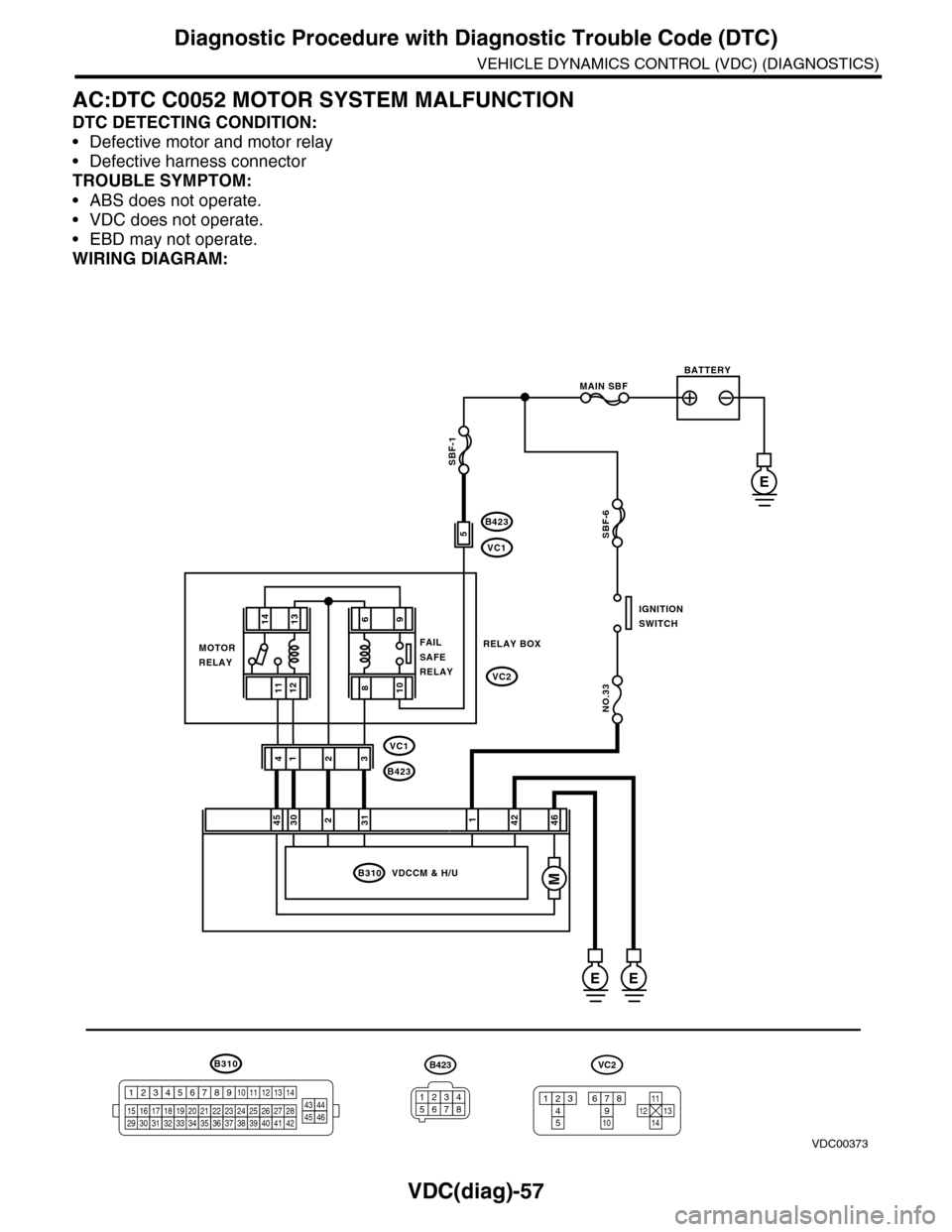
AC:DTC C0052 MOTOR SYSTEM MALFUNCTION
DTC DETECTING CONDITION:
•Defective motor and motor relay
•Defective harness connector
TROUBLE SYMPTOM:
•ABS does not operate.
•VDC does not operate.
•EBD may not operate.
WIRING DIAGRAM:
B310
B423
VC1
B423
VC1
VC2
E
246
2314
B310 VDCCM & H/U
1234
1516171819202122232425262728293031323334353637383940414245464344568910 11 12 13 147
VDC00373
1314
1211
421453031
E
MAIN SBF
SBF-6
NO.33
E
BATTERY
IGNITIONSWITCH
MOTORRELAY
RELAY BOXFAILSAFERELAY
B423
34561278
VC2
12345
678910121311
14
SBF-1
M
96
108
5