2009 SUBARU TRIBECA check engine
[x] Cancel search: check enginePage 1409 of 2453
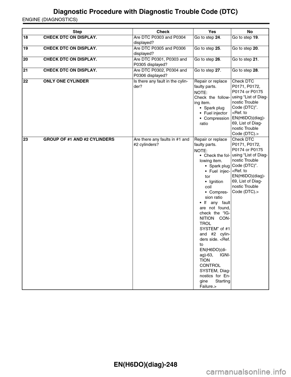
EN(H6DO)(diag)-248
Diagnostic Procedure with Diagnostic Trouble Code (DTC)
ENGINE (DIAGNOSTICS)
18 CHECK DTC ON DISPLAY.Are DTC P0303 and P0304
displayed?
Go to step 24.Go to step 19.
19 CHECK DTC ON DISPLAY.Are DTC P0305 and P0306
displayed?
Go to step 25.Go to step 20.
20 CHECK DTC ON DISPLAY.Are DTC P0301, P0303 and
P0305 displayed?
Go to step 26.Go to step 21.
21 CHECK DTC ON DISPLAY.Are DTC P0302, P0304 and
P0306 displayed?
Go to step 27.Go to step 28.
22 ONLY ONE CYLINDERIs there any fault in the cylin-
der?
Repair or replace
faulty par ts.
NOTE:Check the follow-
ing item.
•Spark plug
•Fuel injector
•Compression
ratio
Check DTC
P0171, P0172,
P0174 or P0175
using “List of Diag-
nostic Trouble
Code (DTC)”.
69, List of Diag-
nostic Trouble
Code (DTC).>
23 GROUP OF #1 AND #2 CYLINDERSAre there any faults in #1 and
#2 cylinders?
Repair or replace
faulty par ts.
NOTE:•Check the fol-
lowing item.
•Spark plug
•Fuel injec-
tor
•Ignition
coil
•Compres-
sion ratio
•If any fault
are not found,
check the “IG-
NITION CON-
TROL
SYSTEM” of #1
and #2 cylin-
ders side.
EN(H6DO)(di-
ag)-63, IGNI-
TION
CONTROL
SYSTEM, Diag-
nostics for En-
gine Starting
Failure.>
Check DTC
P0171, P0172,
P0174 or P0175
using “List of Diag-
nostic Trouble
Code (DTC)”.
69, List of Diag-
nostic Trouble
Code (DTC).>
Step Check Yes No
Page 1410 of 2453
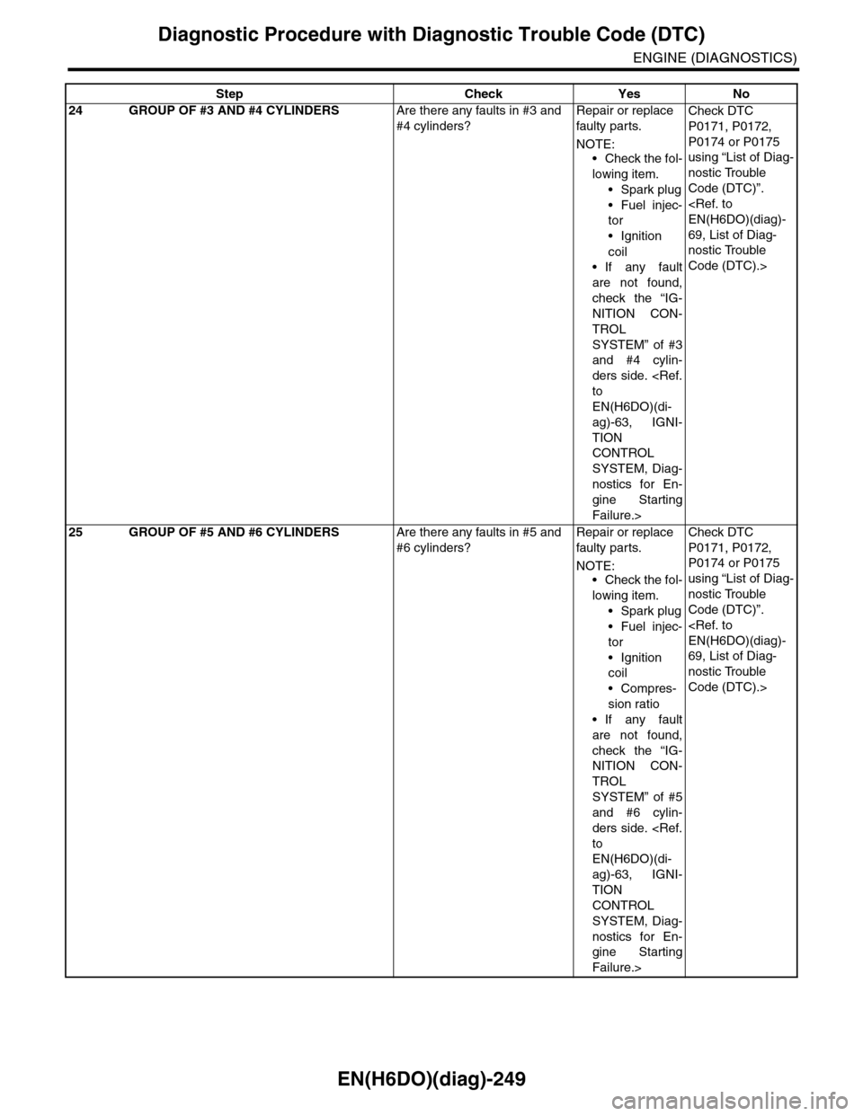
EN(H6DO)(diag)-249
Diagnostic Procedure with Diagnostic Trouble Code (DTC)
ENGINE (DIAGNOSTICS)
24 GROUP OF #3 AND #4 CYLINDERSAre there any faults in #3 and
#4 cylinders?
Repair or replace
faulty par ts.
NOTE:
•Check the fol-
lowing item.
•Spark plug
•Fuel injec-
tor
•Ignition
coil
•If any fault
are not found,
check the “IG-
NITION CON-
TROL
SYSTEM” of #3
and #4 cylin-
ders side.
EN(H6DO)(di-
ag)-63, IGNI-
TION
CONTROL
SYSTEM, Diag-
nostics for En-
gine Starting
Failure.>
Check DTC
P0171, P0172,
P0174 or P0175
using “List of Diag-
nostic Trouble
Code (DTC)”.
69, List of Diag-
nostic Trouble
Code (DTC).>
25 GROUP OF #5 AND #6 CYLINDERSAre there any faults in #5 and
#6 cylinders?
Repair or replace
faulty par ts.
NOTE:•Check the fol-
lowing item.
•Spark plug
•Fuel injec-
tor
•Ignition
coil
•Compres-
sion ratio
•If any fault
are not found,
check the “IG-
NITION CON-
TROL
SYSTEM” of #5
and #6 cylin-
ders side.
EN(H6DO)(di-
ag)-63, IGNI-
TION
CONTROL
SYSTEM, Diag-
nostics for En-
gine Starting
Failure.>
Check DTC
P0171, P0172,
P0174 or P0175
using “List of Diag-
nostic Trouble
Code (DTC)”.
69, List of Diag-
nostic Trouble
Code (DTC).>
Step Check Yes No
Page 1411 of 2453
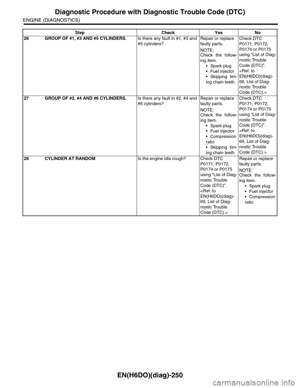
EN(H6DO)(diag)-250
Diagnostic Procedure with Diagnostic Trouble Code (DTC)
ENGINE (DIAGNOSTICS)
26 GROUP OF #1, #3 AND #5 CYLINDERS.Is there any fault in #1, #3 and
#5 cylinders?
Repair or replace
faulty par ts.
NOTE:
Check the follow-
ing item.
•Spark plug
•Fuel injector
•Skipping tim-
ing chain teeth
Check DTC
P0171, P0172,
P0174 or P0175
using “List of Diag-
nostic Trouble
Code (DTC)”.
69, List of Diag-
nostic Trouble
Code (DTC).>
27 GROUP OF #2, #4 AND #6 CYLINDERS.Is there any fault in #2, #4 and
#6 cylinders?
Repair or replace
faulty par ts.
NOTE:Check the follow-
ing item.
•Spark plug
•Fuel injector
•Compression
ratio
•Skipping tim-
ing chain teeth
Check DTC
P0171, P0172,
P0174 or P0175
using “List of Diag-
nostic Trouble
Code (DTC)”.
69, List of Diag-
nostic Trouble
Code (DTC).>
28 CYLINDER AT RANDOMIs the engine idle rough? Check DTC
P0171, P0172,
P0174 or P0175
using “List of Diag-
nostic Trouble
Code (DTC)”.
69, List of Diag-
nostic Trouble
Code (DTC).>
Repair or replace
faulty par ts.
NOTE:Check the follow-
ing item.
•Spark plug
•Fuel injector
•Compression
ratio
Step Check Yes No
Page 1413 of 2453
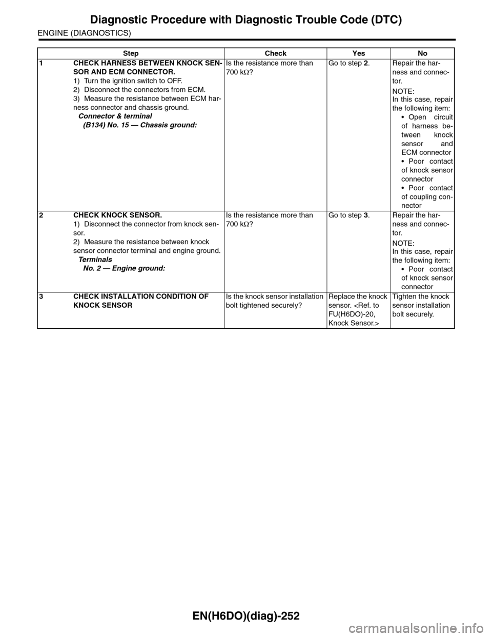
EN(H6DO)(diag)-252
Diagnostic Procedure with Diagnostic Trouble Code (DTC)
ENGINE (DIAGNOSTICS)
Step Check Yes No
1CHECK HARNESS BETWEEN KNOCK SEN-
SOR AND ECM CONNECTOR.
1) Turn the ignition switch to OFF.
2) Disconnect the connectors from ECM.
3) Measure the resistance between ECM har-
ness connector and chassis ground.
Connector & terminal
(B134) No. 15 — Chassis ground:
Is the resistance more than
700 kΩ?
Go to step 2.Repair the har-
ness and connec-
tor.
NOTE:In this case, repair
the following item:
•Open circuit
of harness be-
tween knock
sensor and
ECM connector
•Poor contact
of knock sensor
connector
•Poor contact
of coupling con-
nector
2CHECK KNOCK SENSOR.
1) Disconnect the connector from knock sen-
sor.
2) Measure the resistance between knock
sensor connector terminal and engine ground.
Te r m i n a l s
No. 2 — Engine ground:
Is the resistance more than
700 kΩ?
Go to step 3.Repair the har-
ness and connec-
tor.
NOTE:In this case, repair
the following item:
•Poor contact
of knock sensor
connector
3CHECK INSTALLATION CONDITION OF
KNOCK SENSOR
Is the knock sensor installation
bolt tightened securely?
Replace the knock
sensor.
Knock Sensor.>
Tighten the knock
sensor installation
bolt securely.
Page 1415 of 2453
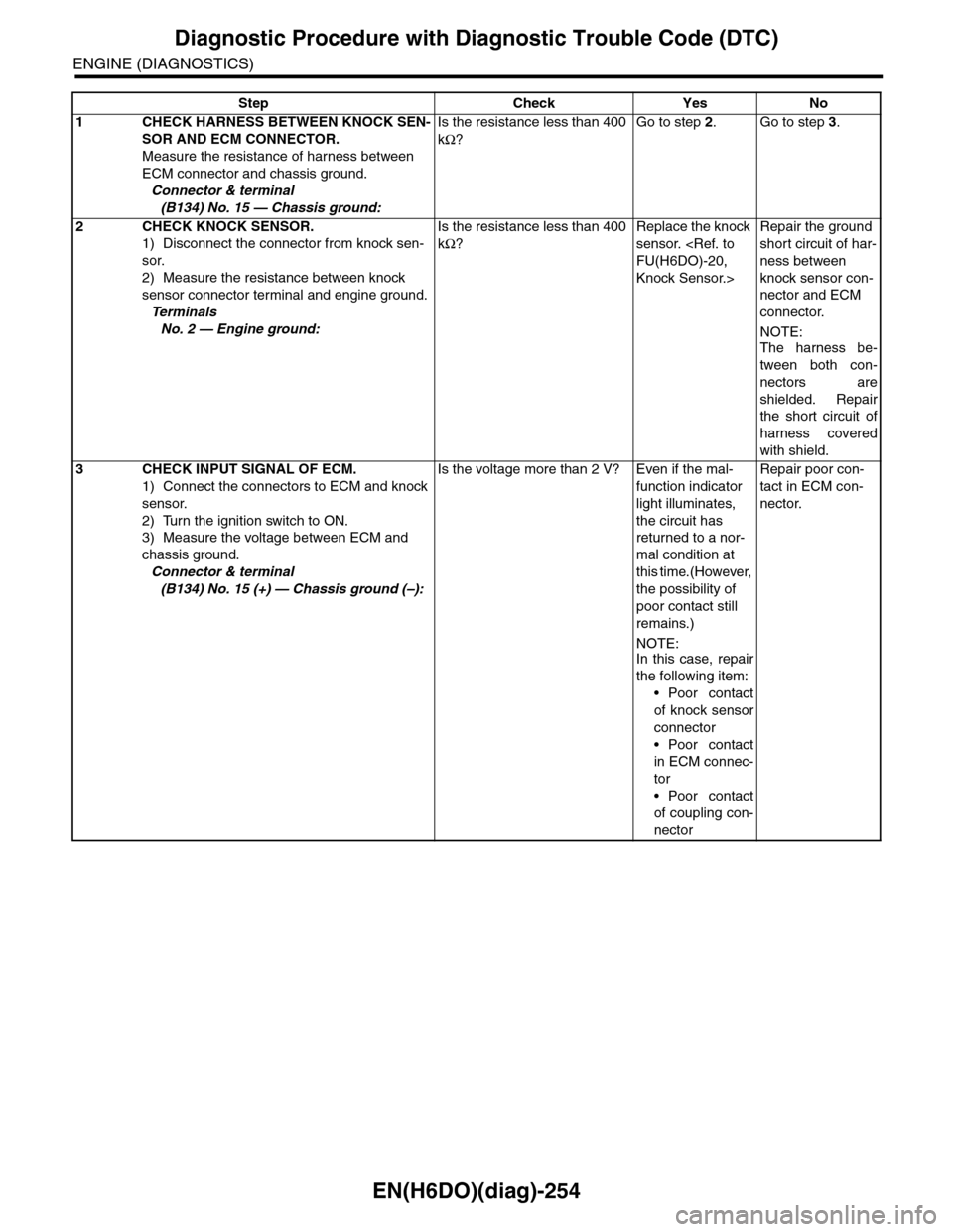
EN(H6DO)(diag)-254
Diagnostic Procedure with Diagnostic Trouble Code (DTC)
ENGINE (DIAGNOSTICS)
Step Check Yes No
1CHECK HARNESS BETWEEN KNOCK SEN-
SOR AND ECM CONNECTOR.
Measure the resistance of harness between
ECM connector and chassis ground.
Connector & terminal
(B134) No. 15 — Chassis ground:
Is the resistance less than 400
kΩ?
Go to step 2.Go to step 3.
2CHECK KNOCK SENSOR.
1) Disconnect the connector from knock sen-
sor.
2) Measure the resistance between knock
sensor connector terminal and engine ground.
Te r m i n a l s
No. 2 — Engine ground:
Is the resistance less than 400
kΩ?
Replace the knock
sensor.
Knock Sensor.>
Repair the ground
short circuit of har-
ness between
knock sensor con-
nector and ECM
connector.
NOTE:
The harness be-
tween both con-
nectors are
shielded. Repair
the short circuit of
harness covered
with shield.
3CHECK INPUT SIGNAL OF ECM.
1) Connect the connectors to ECM and knock
sensor.
2) Turn the ignition switch to ON.
3) Measure the voltage between ECM and
chassis ground.
Connector & terminal
(B134) No. 15 (+) — Chassis ground (–):
Is the voltage more than 2 V? Even if the mal-
function indicator
light illuminates,
the circuit has
returned to a nor-
mal condition at
this time.(However,
the possibility of
poor contact still
remains.)
NOTE:In this case, repair
the following item:
•Poor contact
of knock sensor
connector
•Poor contact
in ECM connec-
tor
•Poor contact
of coupling con-
nector
Repair poor con-
tact in ECM con-
nector.
Page 1417 of 2453
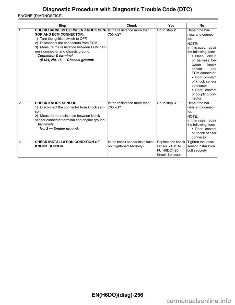
EN(H6DO)(diag)-256
Diagnostic Procedure with Diagnostic Trouble Code (DTC)
ENGINE (DIAGNOSTICS)
Step Check Yes No
1CHECK HARNESS BETWEEN KNOCK SEN-
SOR AND ECM CONNECTOR.
1) Turn the ignition switch to OFF.
2) Disconnect the connectors from ECM.
3) Measure the resistance between ECM har-
ness connector and chassis ground.
Connector & terminal
(B134) No. 16 — Chassis ground:
Is the resistance more than
700 kΩ?
Go to step 2.Repair the har-
ness and connec-
tor.
NOTE:In this case, repair
the following item:
•Open circuit
of harness be-
tween knock
sensor and
ECM connector
•Poor contact
of knock sensor
connector
•Poor contact
of coupling con-
nector
2CHECK KNOCK SENSOR.
1) Disconnect the connector from knock sen-
sor.
2) Measure the resistance between knock
sensor connector terminal and engine ground.
Te r m i n a l s
No. 2 — Engine ground:
Is the resistance more than
700 kΩ?
Go to step 3.Repair the har-
ness and connec-
tor.
NOTE:In this case, repair
the following item:
•Poor contact
of knock sensor
connector
3CHECK INSTALLATION CONDITION OF
KNOCK SENSOR
Is the knock sensor installation
bolt tightened securely?
Replace the knock
sensor.
Knock Sensor.>
Tighten the knock
sensor installation
bolt securely.
Page 1419 of 2453
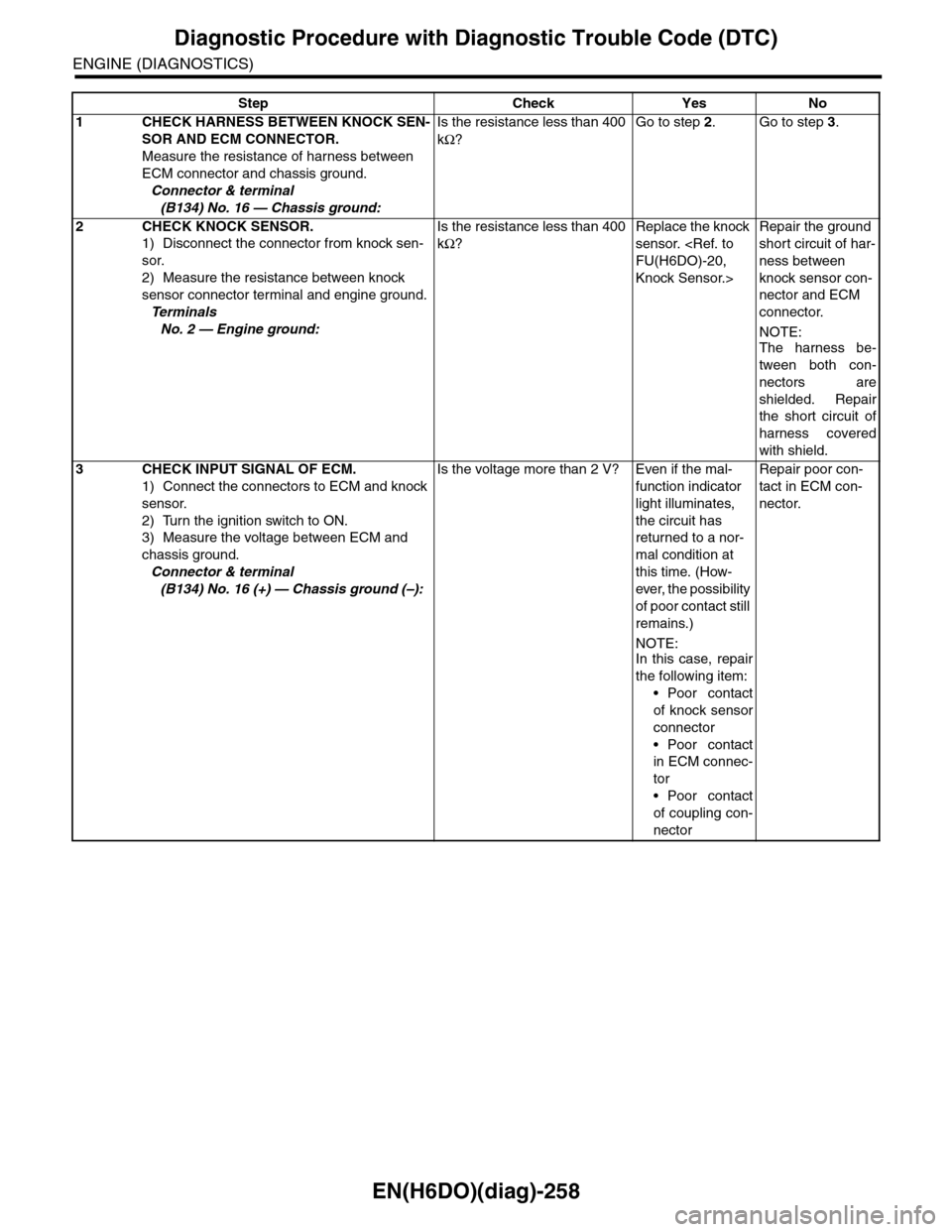
EN(H6DO)(diag)-258
Diagnostic Procedure with Diagnostic Trouble Code (DTC)
ENGINE (DIAGNOSTICS)
Step Check Yes No
1CHECK HARNESS BETWEEN KNOCK SEN-
SOR AND ECM CONNECTOR.
Measure the resistance of harness between
ECM connector and chassis ground.
Connector & terminal
(B134) No. 16 — Chassis ground:
Is the resistance less than 400
kΩ?
Go to step 2.Go to step 3.
2CHECK KNOCK SENSOR.
1) Disconnect the connector from knock sen-
sor.
2) Measure the resistance between knock
sensor connector terminal and engine ground.
Te r m i n a l s
No. 2 — Engine ground:
Is the resistance less than 400
kΩ?
Replace the knock
sensor.
Knock Sensor.>
Repair the ground
short circuit of har-
ness between
knock sensor con-
nector and ECM
connector.
NOTE:
The harness be-
tween both con-
nectors are
shielded. Repair
the short circuit of
harness covered
with shield.
3CHECK INPUT SIGNAL OF ECM.
1) Connect the connectors to ECM and knock
sensor.
2) Turn the ignition switch to ON.
3) Measure the voltage between ECM and
chassis ground.
Connector & terminal
(B134) No. 16 (+) — Chassis ground (–):
Is the voltage more than 2 V? Even if the mal-
function indicator
light illuminates,
the circuit has
returned to a nor-
mal condition at
this time. (How-
ever, the possibility
of poor contact still
remains.)
NOTE:In this case, repair
the following item:
•Poor contact
of knock sensor
connector
•Poor contact
in ECM connec-
tor
•Poor contact
of coupling con-
nector
Repair poor con-
tact in ECM con-
nector.
Page 1421 of 2453
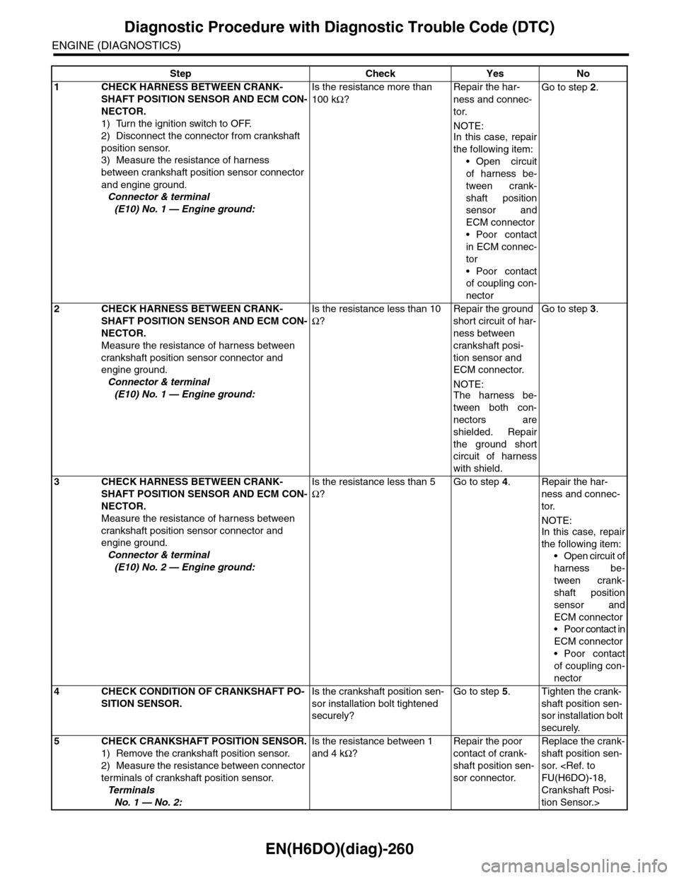
EN(H6DO)(diag)-260
Diagnostic Procedure with Diagnostic Trouble Code (DTC)
ENGINE (DIAGNOSTICS)
Step Check Yes No
1CHECK HARNESS BETWEEN CRANK-
SHAFT POSITION SENSOR AND ECM CON-
NECTOR.
1) Turn the ignition switch to OFF.
2) Disconnect the connector from crankshaft
position sensor.
3) Measure the resistance of harness
between crankshaft position sensor connector
and engine ground.
Connector & terminal
(E10) No. 1 — Engine ground:
Is the resistance more than
100 kΩ?
Repair the har-
ness and connec-
tor.
NOTE:In this case, repair
the following item:
•Open circuit
of harness be-
tween crank-
shaft position
sensor and
ECM connector
•Poor contact
in ECM connec-
tor
•Poor contact
of coupling con-
nector
Go to step 2.
2CHECK HARNESS BETWEEN CRANK-
SHAFT POSITION SENSOR AND ECM CON-
NECTOR.
Measure the resistance of harness between
crankshaft position sensor connector and
engine ground.
Connector & terminal
(E10) No. 1 — Engine ground:
Is the resistance less than 10
Ω?
Repair the ground
short circuit of har-
ness between
crankshaft posi-
tion sensor and
ECM connector.
NOTE:The harness be-
tween both con-
nectors are
shielded. Repair
the ground short
circuit of harness
with shield.
Go to step 3.
3CHECK HARNESS BETWEEN CRANK-
SHAFT POSITION SENSOR AND ECM CON-
NECTOR.
Measure the resistance of harness between
crankshaft position sensor connector and
engine ground.
Connector & terminal
(E10) No. 2 — Engine ground:
Is the resistance less than 5
Ω?
Go to step 4.Repair the har-
ness and connec-
tor.
NOTE:In this case, repair
the following item:
•Open circuit of
harness be-
tween crank-
shaft position
sensor and
ECM connector
•Poor contact in
ECM connector
•Poor contact
of coupling con-
nector
4CHECK CONDITION OF CRANKSHAFT PO-
SITION SENSOR.
Is the crankshaft position sen-
sor installation bolt tightened
securely?
Go to step 5.Tighten the crank-
shaft position sen-
sor installation bolt
securely.
5CHECK CRANKSHAFT POSITION SENSOR.
1) Remove the crankshaft position sensor.
2) Measure the resistance between connector
terminals of crankshaft position sensor.
Te r m i n a l s
No. 1 — No. 2:
Is the resistance between 1
and 4 kΩ?
Repair the poor
contact of crank-
shaft position sen-
sor connector.
Replace the crank-
shaft position sen-
sor.
Crankshaft Posi-
tion Sensor.>