2009 SUBARU TRIBECA check engine
[x] Cancel search: check enginePage 1423 of 2453
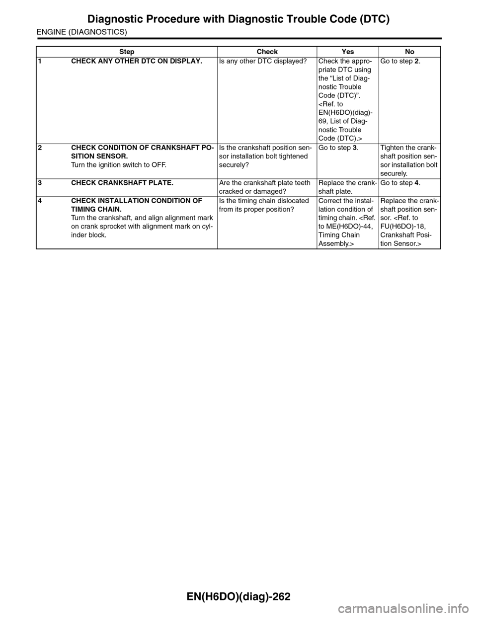
EN(H6DO)(diag)-262
Diagnostic Procedure with Diagnostic Trouble Code (DTC)
ENGINE (DIAGNOSTICS)
Step Check Yes No
1CHECK ANY OTHER DTC ON DISPLAY.Is any other DTC displayed? Check the appro-
priate DTC using
the “List of Diag-
nostic Trouble
Code (DTC)”.
69, List of Diag-
nostic Trouble
Code (DTC).>
Go to step 2.
2CHECK CONDITION OF CRANKSHAFT PO-
SITION SENSOR.
Tu r n t h e i g n i t i o n s w i t c h t o O F F.
Is the crankshaft position sen-
sor installation bolt tightened
securely?
Go to step 3.Tighten the crank-
shaft position sen-
sor installation bolt
securely.
3CHECK CRANKSHAFT PLATE.Are the crankshaft plate teeth
cracked or damaged?
Replace the crank-
shaft plate.
Go to step 4.
4CHECK INSTALLATION CONDITION OF
TIMING CHAIN.
Tu r n t h e c r a n k s h a f t , a n d a l i g n a l i g n m e n t m a r k
on crank sprocket with alignment mark on cyl-
inder block.
Is the timing chain dislocated
from its proper position?
Correct the instal-
lation condition of
timing chain.
Timing Chain
Assembly.>
Replace the crank-
shaft position sen-
sor.
Crankshaft Posi-
tion Sensor.>
Page 1425 of 2453
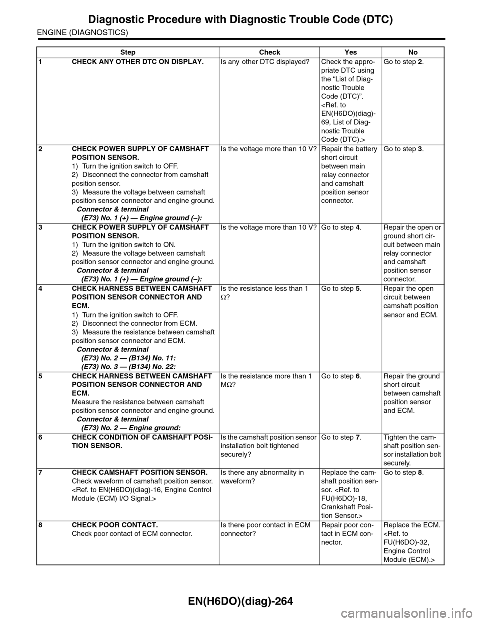
EN(H6DO)(diag)-264
Diagnostic Procedure with Diagnostic Trouble Code (DTC)
ENGINE (DIAGNOSTICS)
Step Check Yes No
1CHECK ANY OTHER DTC ON DISPLAY.Is any other DTC displayed? Check the appro-
priate DTC using
the “List of Diag-
nostic Trouble
Code (DTC)”.
69, List of Diag-
nostic Trouble
Code (DTC).>
Go to step 2.
2CHECK POWER SUPPLY OF CAMSHAFT
POSITION SENSOR.
1) Turn the ignition switch to OFF.
2) Disconnect the connector from camshaft
position sensor.
3) Measure the voltage between camshaft
position sensor connector and engine ground.
Connector & terminal
(E73) No. 1 (+) — Engine ground (–):
Is the voltage more than 10 V? Repair the battery
short circuit
between main
relay connector
and camshaft
position sensor
connector.
Go to step 3.
3CHECK POWER SUPPLY OF CAMSHAFT
POSITION SENSOR.
1) Turn the ignition switch to ON.
2) Measure the voltage between camshaft
position sensor connector and engine ground.
Connector & terminal
(E73) No. 1 (+) — Engine ground (–):
Is the voltage more than 10 V? Go to step 4.Repair the open or
ground short cir-
cuit between main
relay connector
and camshaft
position sensor
connector.
4CHECK HARNESS BETWEEN CAMSHAFT
POSITION SENSOR CONNECTOR AND
ECM.
1) Turn the ignition switch to OFF.
2) Disconnect the connector from ECM.
3) Measure the resistance between camshaft
position sensor connector and ECM.
Connector & terminal
(E73) No. 2 — (B134) No. 11:
(E73) No. 3 — (B134) No. 22:
Is the resistance less than 1
Ω?
Go to step 5.Repair the open
circuit between
camshaft position
sensor and ECM.
5CHECK HARNESS BETWEEN CAMSHAFT
POSITION SENSOR CONNECTOR AND
ECM.
Measure the resistance between camshaft
position sensor connector and engine ground.
Connector & terminal
(E73) No. 2 — Engine ground:
Is the resistance more than 1
MΩ?
Go to step 6.Repair the ground
short circuit
between camshaft
position sensor
and ECM.
6CHECK CONDITION OF CAMSHAFT POSI-
TION SENSOR.
Is the camshaft position sensor
installation bolt tightened
securely?
Go to step 7.Tighten the cam-
shaft position sen-
sor installation bolt
securely.
7CHECK CAMSHAFT POSITION SENSOR.
Check waveform of camshaft position sensor.
Is there any abnormality in
waveform?
Replace the cam-
shaft position sen-
sor.
Crankshaft Posi-
tion Sensor.>
Go to step 8.
8CHECK POOR CONTACT.
Check poor contact of ECM connector.
Is there poor contact in ECM
connector?
Repair poor con-
tact in ECM con-
nector.
Replace the ECM.
Engine Control
Module (ECM).>
Page 1427 of 2453
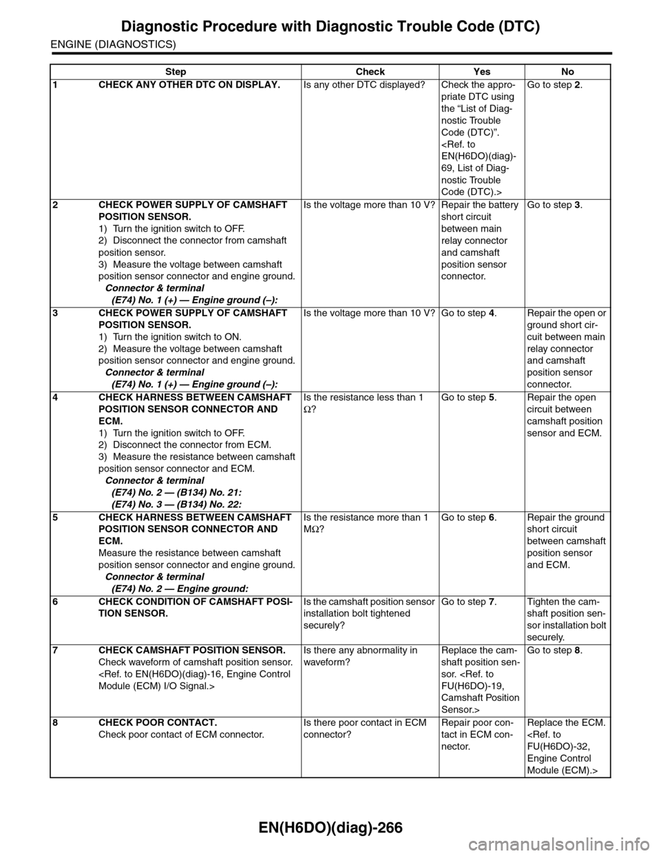
EN(H6DO)(diag)-266
Diagnostic Procedure with Diagnostic Trouble Code (DTC)
ENGINE (DIAGNOSTICS)
Step Check Yes No
1CHECK ANY OTHER DTC ON DISPLAY.Is any other DTC displayed? Check the appro-
priate DTC using
the “List of Diag-
nostic Trouble
Code (DTC)”.
69, List of Diag-
nostic Trouble
Code (DTC).>
Go to step 2.
2CHECK POWER SUPPLY OF CAMSHAFT
POSITION SENSOR.
1) Turn the ignition switch to OFF.
2) Disconnect the connector from camshaft
position sensor.
3) Measure the voltage between camshaft
position sensor connector and engine ground.
Connector & terminal
(E74) No. 1 (+) — Engine ground (–):
Is the voltage more than 10 V? Repair the battery
short circuit
between main
relay connector
and camshaft
position sensor
connector.
Go to step 3.
3CHECK POWER SUPPLY OF CAMSHAFT
POSITION SENSOR.
1) Turn the ignition switch to ON.
2) Measure the voltage between camshaft
position sensor connector and engine ground.
Connector & terminal
(E74) No. 1 (+) — Engine ground (–):
Is the voltage more than 10 V? Go to step 4.Repair the open or
ground short cir-
cuit between main
relay connector
and camshaft
position sensor
connector.
4CHECK HARNESS BETWEEN CAMSHAFT
POSITION SENSOR CONNECTOR AND
ECM.
1) Turn the ignition switch to OFF.
2) Disconnect the connector from ECM.
3) Measure the resistance between camshaft
position sensor connector and ECM.
Connector & terminal
(E74) No. 2 — (B134) No. 21:
(E74) No. 3 — (B134) No. 22:
Is the resistance less than 1
Ω?
Go to step 5.Repair the open
circuit between
camshaft position
sensor and ECM.
5CHECK HARNESS BETWEEN CAMSHAFT
POSITION SENSOR CONNECTOR AND
ECM.
Measure the resistance between camshaft
position sensor connector and engine ground.
Connector & terminal
(E74) No. 2 — Engine ground:
Is the resistance more than 1
MΩ?
Go to step 6.Repair the ground
short circuit
between camshaft
position sensor
and ECM.
6CHECK CONDITION OF CAMSHAFT POSI-
TION SENSOR.
Is the camshaft position sensor
installation bolt tightened
securely?
Go to step 7.Tighten the cam-
shaft position sen-
sor installation bolt
securely.
7CHECK CAMSHAFT POSITION SENSOR.
Check waveform of camshaft position sensor.
Is there any abnormality in
waveform?
Replace the cam-
shaft position sen-
sor.
Camshaft Position
Sensor.>
Go to step 8.
8CHECK POOR CONTACT.
Check poor contact of ECM connector.
Is there poor contact in ECM
connector?
Repair poor con-
tact in ECM con-
nector.
Replace the ECM.
Engine Control
Module (ECM).>
Page 1430 of 2453
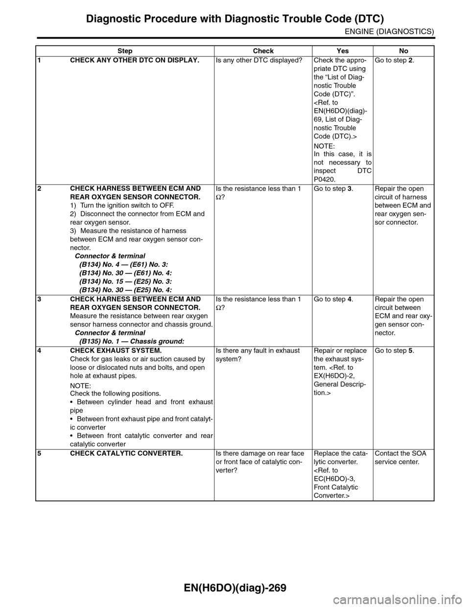
EN(H6DO)(diag)-269
Diagnostic Procedure with Diagnostic Trouble Code (DTC)
ENGINE (DIAGNOSTICS)
Step Check Yes No
1CHECK ANY OTHER DTC ON DISPLAY.Is any other DTC displayed? Check the appro-
priate DTC using
the “List of Diag-
nostic Trouble
Code (DTC)”.
69, List of Diag-
nostic Trouble
Code (DTC).>
NOTE:In this case, it is
not necessary to
inspect DTC
P0420.
Go to step 2.
2CHECK HARNESS BETWEEN ECM AND
REAR OXYGEN SENSOR CONNECTOR.
1) Turn the ignition switch to OFF.
2) Disconnect the connector from ECM and
rear oxygen sensor.
3) Measure the resistance of harness
between ECM and rear oxygen sensor con-
nector.
Connector & terminal
(B134) No. 4 — (E61) No. 3:
(B134) No. 30 — (E61) No. 4:
(B134) No. 15 — (E25) No. 3:
(B134) No. 30 — (E25) No. 4:
Is the resistance less than 1
Ω?
Go to step 3.Repair the open
circuit of harness
between ECM and
rear oxygen sen-
sor connector.
3CHECK HARNESS BETWEEN ECM AND
REAR OXYGEN SENSOR CONNECTOR.
Measure the resistance between rear oxygen
sensor harness connector and chassis ground.
Connector & terminal
(B135) No. 1 — Chassis ground:
Is the resistance less than 1
Ω?
Go to step 4.Repair the open
circuit between
ECM and rear oxy-
gen sensor con-
nector.
4 CHECK EXHAUST SYSTEM.
Check for gas leaks or air suction caused by
loose or dislocated nuts and bolts, and open
hole at exhaust pipes.
NOTE:Check the following positions.
•Between cylinder head and front exhaust
pipe
•Between front exhaust pipe and front catalyt-
ic converter
•Between front catalytic converter and rear
catalytic converter
Is there any fault in exhaust
system?
Repair or replace
the exhaust sys-
tem.
General Descrip-
tion.>
Go to step 5.
5CHECK CATALYTIC CONVERTER.Is there damage on rear face
or front face of catalytic con-
ver ter?
Replace the cata-
lytic converter.
Front Catalytic
Converter.>
Contact the SOA
service center.
Page 1431 of 2453
EN(H6DO)(diag)-270
Diagnostic Procedure with Diagnostic Trouble Code (DTC)
ENGINE (DIAGNOSTICS)
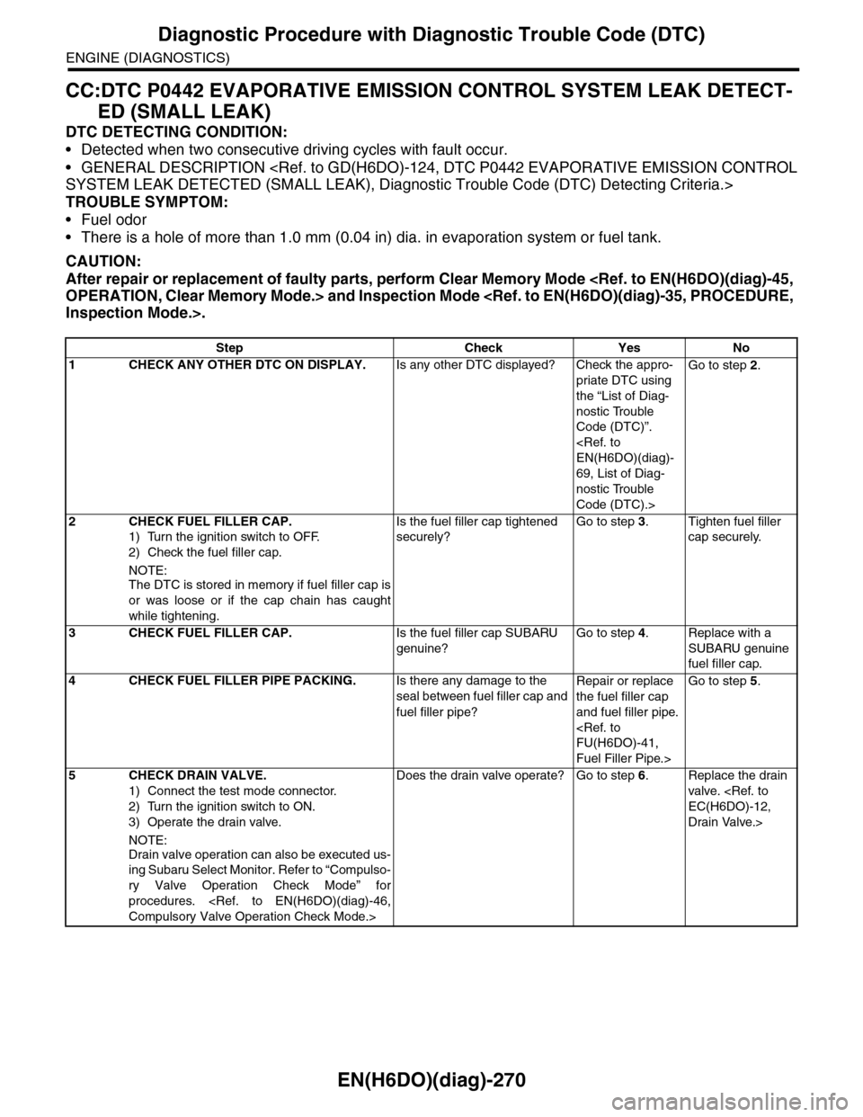
CC:DTC P0442 EVAPORATIVE EMISSION CONTROL SYSTEM LEAK DETECT-
ED (SMALL LEAK)
DTC DETECTING CONDITION:
•Detected when two consecutive driving cycles with fault occur.
•GENERAL DESCRIPTION
TROUBLE SYMPTOM:
•Fuel odor
•There is a hole of more than 1.0 mm (0.04 in) dia. in evaporation system or fuel tank.
CAUTION:
After repair or replacement of faulty parts, perform Clear Memory Mode
Step Check Yes No
1CHECK ANY OTHER DTC ON DISPLAY.Is any other DTC displayed? Check the appro-
priate DTC using
the “List of Diag-
nostic Trouble
Code (DTC)”.
69, List of Diag-
nostic Trouble
Code (DTC).>
Go to step 2.
2CHECK FUEL FILLER CAP.
1) Turn the ignition switch to OFF.
2) Check the fuel filler cap.
NOTE:
The DTC is stored in memory if fuel filler cap is
or was loose or if the cap chain has caught
while tightening.
Is the fuel filler cap tightened
securely?
Go to step 3.Tighten fuel filler
cap securely.
3CHECK FUEL FILLER CAP.Is the fuel filler cap SUBARU
genuine?
Go to step 4.Replace with a
SUBARU genuine
fuel filler cap.
4CHECK FUEL FILLER PIPE PACKING.Is there any damage to the
seal between fuel filler cap and
fuel filler pipe?
Repair or replace
the fuel filler cap
and fuel filler pipe.
Fuel Filler Pipe.>
Go to step 5.
5CHECK DRAIN VALVE.
1) Connect the test mode connector.
2) Turn the ignition switch to ON.
3) Operate the drain valve.
NOTE:
Drain valve operation can also be executed us-
ing Subaru Select Monitor. Refer to “Compulso-
ry Valve Operation Check Mode” for
procedures.
Does the drain valve operate? Go to step 6.Replace the drain
valve.
Drain Valve.>
Page 1432 of 2453
EN(H6DO)(diag)-271
Diagnostic Procedure with Diagnostic Trouble Code (DTC)
ENGINE (DIAGNOSTICS)
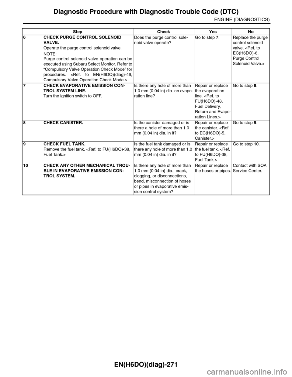
6CHECK PURGE CONTROL SOLENOID
VALVE.
Operate the purge control solenoid valve.
NOTE:Purge control solenoid valve operation can be
executed using Subaru Select Monitor. Refer to
“Compulsory Valve Operation Check Mode” for
procedures.
Does the purge control sole-
noid valve operate?
Go to step 7.Replace the purge
control solenoid
valve.
Purge Control
Solenoid Valve.>
7CHECK EVAPORATIVE EMISSION CON-
TROL SYSTEM LINE.
Tu r n t h e i g n i t i o n s w i t c h t o O F F.
Is there any hole of more than
1.0 mm (0.04 in) dia. on evapo-
ration line?
Repair or replace
the evaporation
line.
Fuel Delivery,
Return and Evapo-
ration Lines.>
Go to step 8.
8CHECK CANISTER.Is the canister damaged or is
there a hole of more than 1.0
mm (0.04 in) dia. in it?
Repair or replace
the canister.
Canister.>
Go to step 9.
9CHECK FUEL TANK.
Remove the fuel tank.
Is the fuel tank damaged or is
there any hole of more than 1.0
mm (0.04 in) dia. in it?
Repair or replace
the fuel tank.
Fuel Tank.>
Go to step 10.
10 CHECK ANY OTHER MECHANICAL TROU-
BLE IN EVAPORATIVE EMISSION CON-
TROL SYSTEM.
Is there any hole of more than
1.0 mm (0.04 in) dia., crack,
clogging, or disconnections,
bend, misconnection of hoses
or pipes in evaporative emis-
sion control system?
Repair or replace
the hoses or pipes.
Contact with SOA
Service Center.
Step Check Yes No
Page 1434 of 2453
EN(H6DO)(diag)-273
Diagnostic Procedure with Diagnostic Trouble Code (DTC)
ENGINE (DIAGNOSTICS)
Step Check Yes No
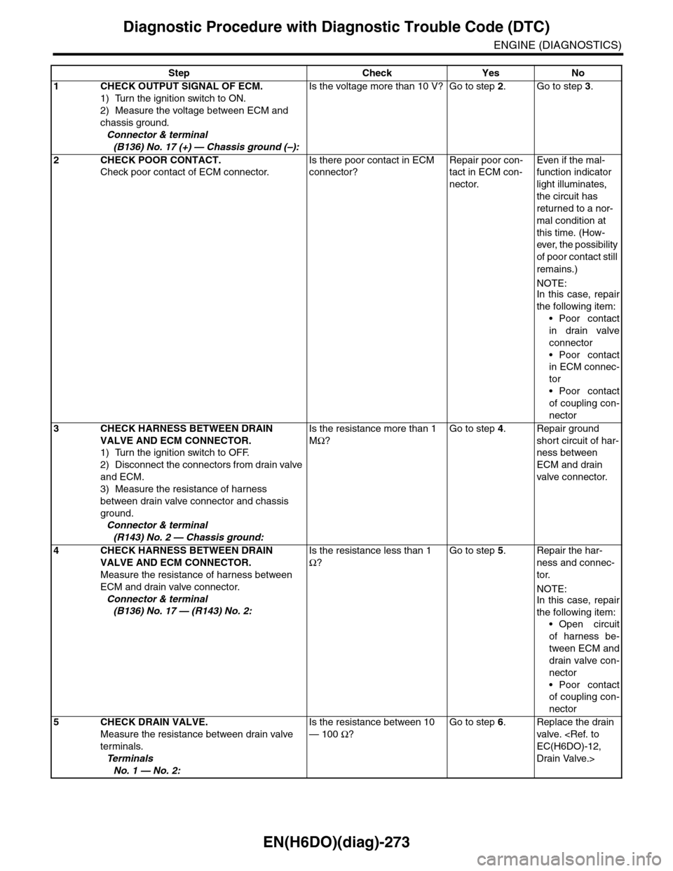
1CHECK OUTPUT SIGNAL OF ECM.
1) Turn the ignition switch to ON.
2) Measure the voltage between ECM and
chassis ground.
Connector & terminal
(B136) No. 17 (+) — Chassis ground (–):
Is the voltage more than 10 V? Go to step 2.Go to step 3.
2CHECK POOR CONTACT.
Check poor contact of ECM connector.
Is there poor contact in ECM
connector?
Repair poor con-
tact in ECM con-
nector.
Even if the mal-
function indicator
light illuminates,
the circuit has
returned to a nor-
mal condition at
this time. (How-
ever, the possibility
of poor contact still
remains.)
NOTE:In this case, repair
the following item:
•Poor contact
in drain valve
connector
•Poor contact
in ECM connec-
tor
•Poor contact
of coupling con-
nector
3CHECK HARNESS BETWEEN DRAIN
VALVE AND ECM CONNECTOR.
1) Turn the ignition switch to OFF.
2) Disconnect the connectors from drain valve
and ECM.
3) Measure the resistance of harness
between drain valve connector and chassis
ground.
Connector & terminal
(R143) No. 2 — Chassis ground:
Is the resistance more than 1
MΩ?
Go to step 4.Repair ground
short circuit of har-
ness between
ECM and drain
valve connector.
4CHECK HARNESS BETWEEN DRAIN
VALVE AND ECM CONNECTOR.
Measure the resistance of harness between
ECM and drain valve connector.
Connector & terminal
(B136) No. 17 — (R143) No. 2:
Is the resistance less than 1
Ω?
Go to step 5.Repair the har-
ness and connec-
tor.
NOTE:In this case, repair
the following item:
•Open circuit
of harness be-
tween ECM and
drain valve con-
nector
•Poor contact
of coupling con-
nector
5CHECK DRAIN VALVE.
Measure the resistance between drain valve
terminals.
Te r m i n a l s
No. 1 — No. 2:
Is the resistance between 10
— 100 Ω?
Go to step 6.Replace the drain
valve.
Drain Valve.>
Page 1435 of 2453
EN(H6DO)(diag)-274
Diagnostic Procedure with Diagnostic Trouble Code (DTC)
ENGINE (DIAGNOSTICS)
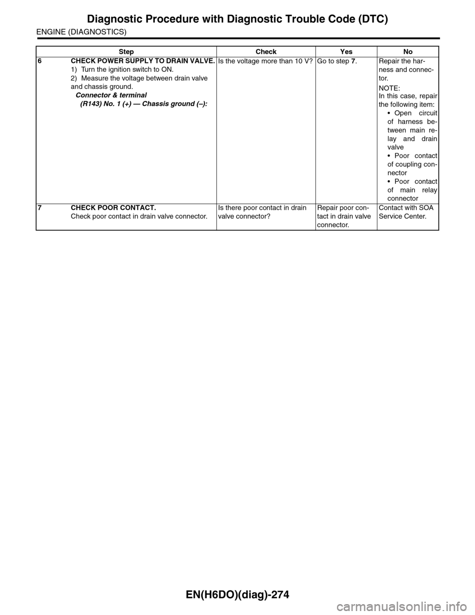
6CHECK POWER SUPPLY TO DRAIN VALVE.
1) Turn the ignition switch to ON.
2) Measure the voltage between drain valve
and chassis ground.
Connector & terminal
(R143) No. 1 (+) — Chassis ground (–):
Is the voltage more than 10 V? Go to step 7.Repair the har-
ness and connec-
tor.
NOTE:In this case, repair
the following item:
•Open circuit
of harness be-
tween main re-
lay and drain
valve
•Poor contact
of coupling con-
nector
•Poor contact
of main relay
connector
7CHECK POOR CONTACT.
Check poor contact in drain valve connector.
Is there poor contact in drain
valve connector?
Repair poor con-
tact in drain valve
connector.
Contact with SOA
Service Center.
Step Check Yes No