Page 738 of 2453

BR-24
Master Cylinder
BRAKE
8. Master Cylinder
A: REMOVAL
CAUTION:
Do not allow brake fluid to come in contact with
vehicle body. If it does, wash off with water and
wipe away completely.
1) Drain brake fluid from the reservoir tank com-
pletely.
2) Disconnect the harness connector of the fluid
level gauge.
3) Remove the brake pipe from the master cylinder.
4) Remove the master cylinder mounting nuts, and
remove the master cylinder from the brake booster.
B: INSTALLATION
1) Install in the reverse order of removal.
Tightening torque:
Master cylinder mounting nut
25 N·m (2.5 kgf-m, 18.4 ft-lb)
Brake pipe
19 N·m (1.9 kgf-m, 14.0 ft-lb)
CAUTION:
Be sure to use recommended brake fluid.
2) Bleed air from brake system.
PROCEDURE, Air Bleeding.>
C: REPLACEMENT
1) Remove mud and dirt from the surface of brake
master cylinder.
2) Secure the master cylinder in a vise.
NOTE:
To avoid damaging the master cylinder, place be-
tween aluminum plates or other material when
holding with a vise.
3) Remove the pin which secures the master cylin-
der and reservoir tank, then remove the reservoir
tank and seal.
4) While pushing in the primary piston, remove the
C-ring using pliers.
5) While pushing in the primary piston, remove the
straight pin from the port on the reservoir tank at-
tachment location using a magnet pick-up tool.
6) Extract the primary piston assembly and sec-
ondary piston assembly straight out while taking
care not to scratch the inner surface of the cylin-
ders.
7) Clean the inside of master cylinder with brake
fluid. Check the inside of the cylinder for damage,
deformation and wear. Replace the master cylinder
as assembly if faulty.
8) Apply brake fluid to the inner surface of master
cylinder and piston assembly.
9) Make sure that the inner surface of master cylin-
der and the piston assembly are free of foreign
matter. Install the primary piston assembly and the
secondary piston assembly to master cylinder,
while taking care not to scratch the master cylinder
inner surface.
10) While pushing-in the primary piston, install the
cylinder pin.
BR-00499
(1) Straight pin
BR-00169
(1)
BR-00069
Page 750 of 2453

BR-36
Brake Pedal
BRAKE
14.Brake Pedal
A: REMOVAL
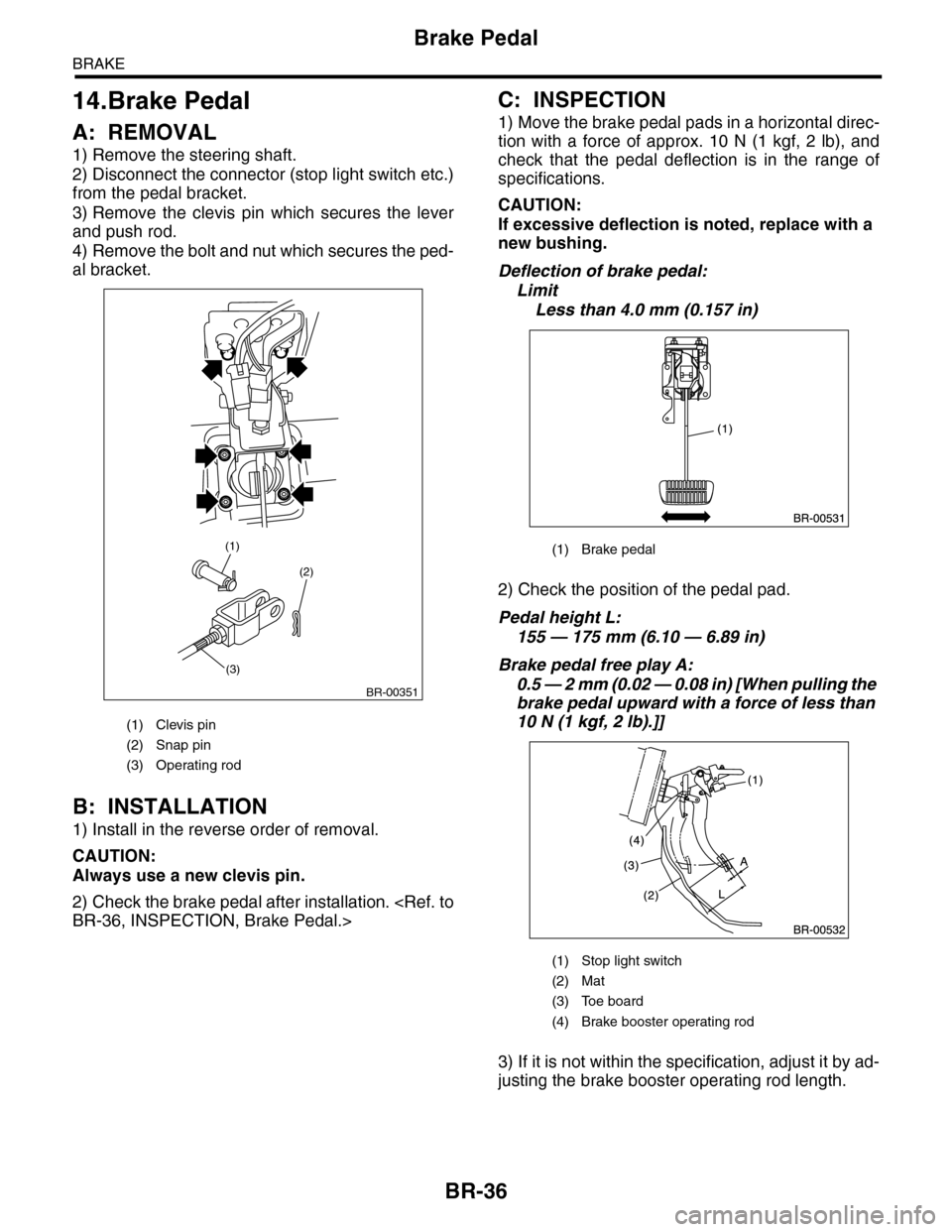
1) Remove the steering shaft.
2) Disconnect the connector (stop light switch etc.)
from the pedal bracket.
3) Remove the clevis pin which secures the lever
and push rod.
4) Remove the bolt and nut which secures the ped-
al bracket.
B: INSTALLATION
1) Install in the reverse order of removal.
CAUTION:
Always use a new clevis pin.
2) Check the brake pedal after installation.
BR-36, INSPECTION, Brake Pedal.>
C: INSPECTION
1) Move the brake pedal pads in a horizontal direc-
tion with a force of approx. 10 N (1 kgf, 2 lb), and
check that the pedal deflection is in the range of
specifications.
CAUTION:
If excessive deflection is noted, replace with a
new bushing.
Deflection of brake pedal:
Limit
Less than 4.0 mm (0.157 in)
2) Check the position of the pedal pad.
Pedal height L:
155 — 175 mm (6.10 — 6.89 in)
Brake pedal free play A:
0.5 — 2 mm (0.02 — 0.08 in) [When pulling the
brake pedal upward with a force of less than
10 N (1 kgf, 2 lb).]]
3) If it is not within the specification, adjust it by ad-
justing the brake booster operating rod length.
(1) Clevis pin
(2) Snap pin
(3) Operating rod
(2)
(3)
(1)
BR-00351
(1) Brake pedal
(1) Stop light switch
(2) Mat
(3) Toe board
(4) Brake booster operating rod
Page 753 of 2453

BR-39
Brake Vacuum Pump
BRAKE
16.Brake Vacuum Pump
A: REMOVAL
1. BRAKE VACUUM PUMP
1) Disconnect the ground cable from the battery.
2) Disconnect the brake vacuum pump connector.
3) Remove the vacuum hose.
4) Remove the bolt, and remove the brake vacuum
pump.
2. VACUUM HOSE
Remove the clip and remove the vacuum hose.
B: INSTALLATION
1. BRAKE VACUUM PUMP
Install in the reverse order of removal.
Tightening torque:
7.5 N·m (0.76 kgf-m, 5.5 ft-lb)
2. VACUUM HOSE
Install in the reverse order of removal.
CAUTION:
The vacuum hose has an installation direction.
Make sure to install in the proper direction.
C: INSPECTION
1. BRAKE VACUUM PUMP
Inspect for whether or not the pump operates when
battery voltage is applied to the connector terminal.
2. VACUUM HOSE
Check to see that air only flows in one direction,
when air is blown into or sucked from the hose.
(1) To engine
(2) Vacuum hose
(3) Vacuum pipe
(4) Marking (Marking to vacuum pipe side)
BR-00506
BR-00507
(1)
(2)(2)
(4)
(3)
ENG
Page 754 of 2453
BR-40
Brake Vacuum Sensor
BRAKE
17.Brake Vacuum Sensor
A: REMOVAL
1) Disconnect the ground cable from the battery.
2) Disconnect the brake vacuum sensor connector.
3) Remove the vacuum hose from the brake vacu-
um sensor.
4) Remove the bolt, and remove the brake vacuum
sensor.
B: INSTALLATION
Install in the reverse order of removal.
Tightening torque:
7.5 N·m (0.76 kgf-m, 5.5 ft-lb)
BR-00509
Page 803 of 2453

DI-19
Rear Differential (VA–type)
DIFFERENTIALS
14) Extract the companion flange with a puller.
15) Removes the drive pinion shaft.
16) Remove the rear bearing cone from drive pin-
ion by supporting the cone with ST.
NOTE:
Place the replacer so that its center-recessed side
faces the pinion gear.
ST 398517700 REPLACER
17) Remove the front oil seal from differential carri-
er using screwdriver.
18) Remove the pilot bearing, front bearing cone
and collar.
19) When replacing the bearings, hit out the front
bearing cup and rear bearing cup in this order out of
case using a brass bar.
D: ASSEMBLY
NOTE:
•Assemble in the reverse order of disassembly.
•Check and adjust each part during assembly.
•Use a new gasket.
•Keep the shims and washers in order, so that
they are not improperly installed.
•Thoroughly clean the surfaces on which the
shims, washers and bearings are to be installed.
•Apply gear oil when installing the bearings and
thrust washers.
•Be careful not to mix up the RH and LH bearing
races.
•Replace the oil seal with a new one at every dis-
assembly. Apply grease to the lips when installing
the oil seal.
•Be careful not to mix up the differential oil seal
RH and LH.
(A) Companion flange
(B) Puller
(A) Pilot bearing
(B) Collar
(C) Front bearing
(D) Rear bearing cup
(B)
(A)
DI-00394
DI-00373
ST
(B)(A)(C)(D)
DI-00374
(A) 2 cutout portions along diagonal lines
(B) Tap alternately with brass bar.
(B)
(A)
DI-00077
DI-00078
Page 805 of 2453

DI-21
Rear Differential (VA–type)
DIFFERENTIALS
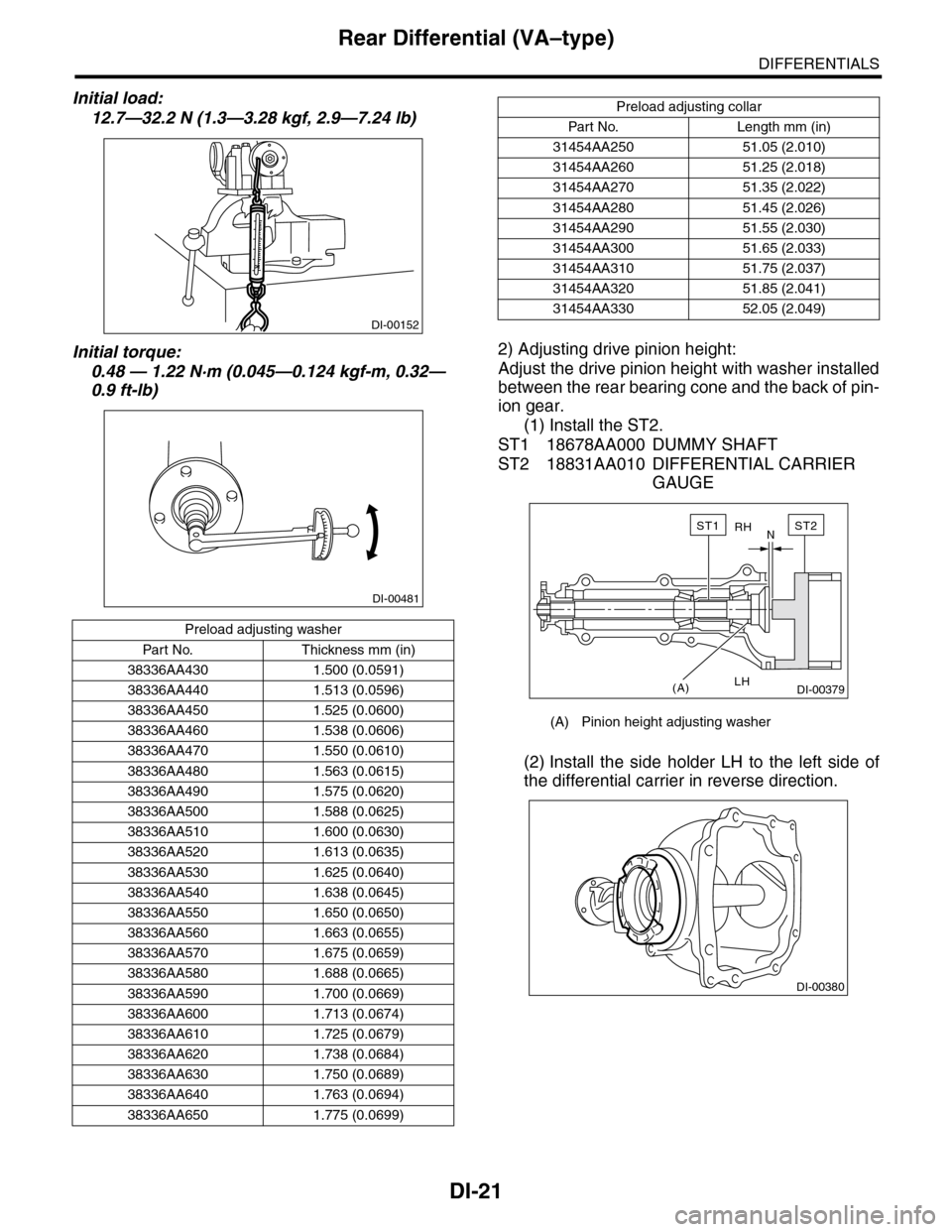
Initial load:
12.7—32.2 N (1.3—3.28 kgf, 2.9—7.24 lb)
Initial torque:
0.48 — 1.22 N·m (0.045—0.124 kgf-m, 0.32—
0.9 ft-lb)
2) Adjusting drive pinion height:
Adjust the drive pinion height with washer installed
between the rear bearing cone and the back of pin-
ion gear.
(1) Install the ST2.
ST1 18678AA000 DUMMY SHAFT
ST2 18831AA010 DIFFERENTIAL CARRIER
GAUGE
(2) Install the side holder LH to the left side of
the differential carrier in reverse direction.
Preload adjusting washer
Par t No. Thickness mm (in)
38336AA430 1.500 (0.0591)
38336AA440 1.513 (0.0596)
38336AA450 1.525 (0.0600)
38336AA460 1.538 (0.0606)
38336AA470 1.550 (0.0610)
38336AA480 1.563 (0.0615)
38336AA490 1.575 (0.0620)
38336AA500 1.588 (0.0625)
38336AA510 1.600 (0.0630)
38336AA520 1.613 (0.0635)
38336AA530 1.625 (0.0640)
38336AA540 1.638 (0.0645)
38336AA550 1.650 (0.0650)
38336AA560 1.663 (0.0655)
38336AA570 1.675 (0.0659)
38336AA580 1.688 (0.0665)
38336AA590 1.700 (0.0669)
38336AA600 1.713 (0.0674)
38336AA610 1.725 (0.0679)
38336AA620 1.738 (0.0684)
38336AA630 1.750 (0.0689)
38336AA640 1.763 (0.0694)
38336AA650 1.775 (0.0699)
DI-00152
DI-00481
Preload adjusting collar
Par t No. Length mm (in)
31454AA250 51.05 (2.010)
31454AA260 51.25 (2.018)
31454AA270 51.35 (2.022)
31454AA280 51.45 (2.026)
31454AA290 51.55 (2.030)
31454AA300 51.65 (2.033)
31454AA310 51.75 (2.037)
31454AA320 51.85 (2.041)
31454AA330 52.05 (2.049)
(A) Pinion height adjusting washer
RH
LH
N
(A)
ST2ST1
DI-00379
DI-00380
Page 808 of 2453
DI-24
Rear Differential (VA–type)
DIFFERENTIALS
12) Install the hypoid driven gear to differential
case.
NOTE:
•Tighten diagonally while tapping the bolt heads.
•Set a cushioning such as wooden block, alumi-
num plate or shop cloth between vise and differen-
tial case if the side gear comes into contact with
vise.
Tightening torque:
62 N·m (6.3 kgf-m, 45.6 ft-lb)
13) Press the side bearing into differential case us-
ing ST.
ST 398487700 DRIFT
14) Assemble holders.
(1) Install the new oil seal into holder RH and
LH.
ST 498447100 INSTALLER
(2) Install the bearing race into holder RH and
LH.
ST 398177700 INSTALLER
CAUTION:
Make sure that the RH and LH oil seals, bearing
outer races and cones are properly assembled.
(3) Install the differential assembly into differen-
tial carrier in the reverse order of disassembly.
(4) Temporally tighten the side holders RH and
LH in differential carrier to install.
DI-00371
ST
DI-00095
ST
DI-00166
ST
DI-00167
DI-00366
Page 815 of 2453
DI-31
Rear Differential Front Oil Seal
DIFFERENTIALS
12) Install the companion flange.
NOTE:
Use a plastic hammer to install companion flange.
13) Apply Lock Tite to the drive pinion shaft screw
threads and the nut seat surface.
Lock Tite:
THREE BOND 1324 (Part No. 004403042)
14) Tighten the self-locking nut within the specified
torque range so that the rotating resistance of com-
panion flange becomes the same as that of before
oil seal replacement.
ST 498427200 FLANGE WRENCH
NOTE:
Use a new self-locking nut.
Tightening torque:
191 N·m (19.5 kgf-m, 141 ft-lb)
15) Hereafter, reassemble in the reverse order of
disassembly.
DI-00194
ST