Page 945 of 2453

RS-12
Rear Shock Absorber
REAR SUSPENSION
6. Rear Shock Absorber
A: REMOVAL
1) Remove the strut cap of quarter trim.
2) Lift-up the vehicle, and then remove the rear
wheels.
3) Remove the nut and detach the rear stabilizer link.
4) Remove the bolts on the bottom side of the
shock absorber.
5) Detach the rear lateral link.
6) Remove the nuts of the shock absorber mount.
7) Remove the shock absorber.
B: INSTALLATION
NOTE:
•Be sure to use a new self-locking nut.
•Always tighten the stabilizer bushing in the state
where the vehicle is at curb weight and the wheels
are in full contact with the ground.
1) Install in the reverse order of removal.
CAUTION:
Attach so that the protrusion on the top of the
mount is pointed towards the front of the vehicle.
Tightening torque:
Refer to “COMPONENT” of “General Descrip-
tion” for the tightening torque.
COMPONENT, General Description.>
2) Check the wheel alignment and adjust it if nec-
essary.
C: DISASSEMBLY
Refer to “Front Strut” for disassembly procedure.
D: ASSEMBLY
Refer to “Front Strut” for installation procedures.
E: INSPECTION
Refer to “Front Strut” for inspection procedures.
RS-00185
RS-00186
RS-00187
RS-00188
(1) Mount
(2) Protrusion por tion
(3) Front side of vehicle
Page 947 of 2453

RS-14
Front Lateral Link
REAR SUSPENSION
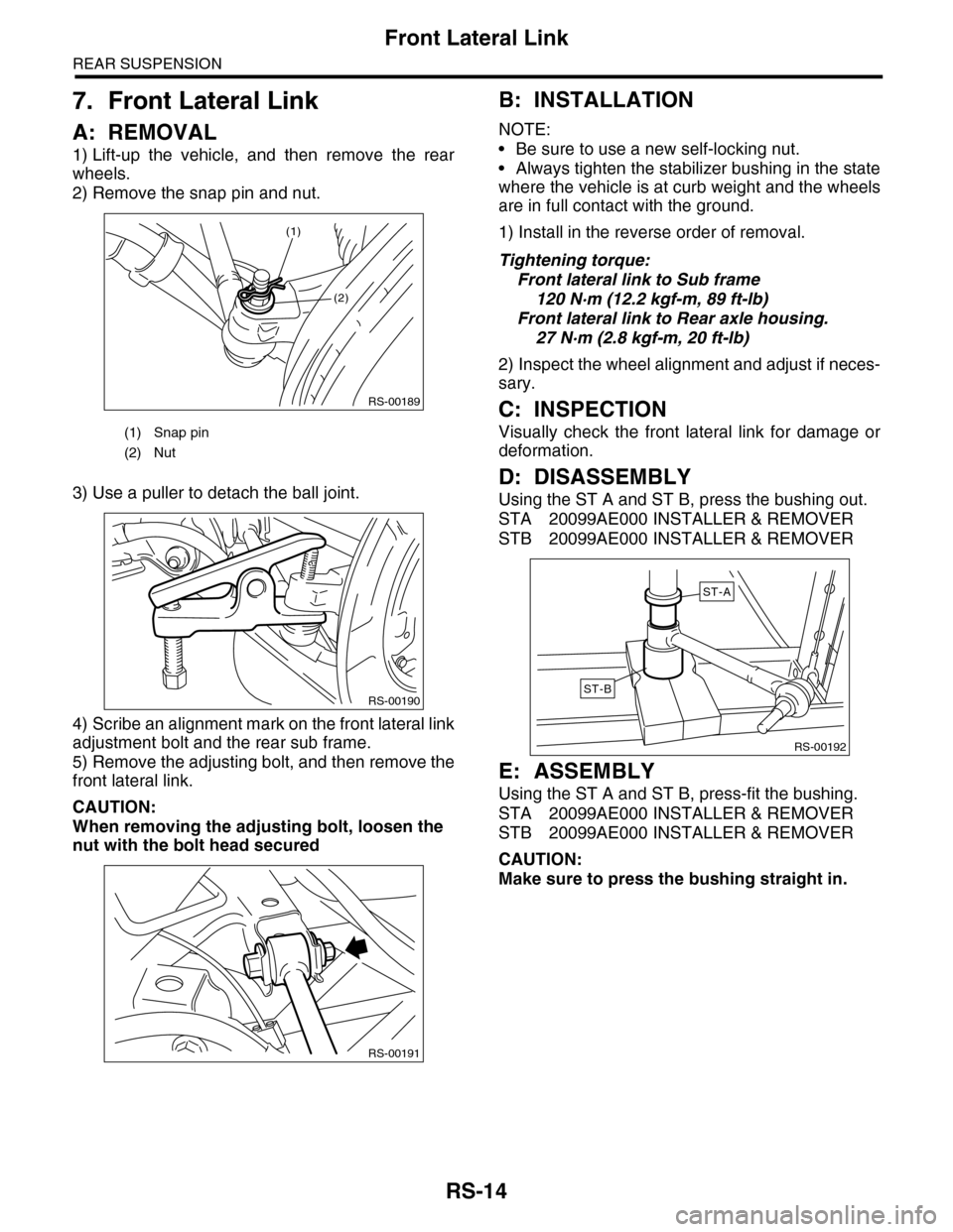
7. Front Lateral Link
A: REMOVAL
1) Lift-up the vehicle, and then remove the rear
wheels.
2) Remove the snap pin and nut.
3) Use a puller to detach the ball joint.
4) Scribe an alignment mark on the front lateral link
adjustment bolt and the rear sub frame.
5) Remove the adjusting bolt, and then remove the
front lateral link.
CAUTION:
When removing the adjusting bolt, loosen the
nut with the bolt head secured
B: INSTALLATION
NOTE:
•Be sure to use a new self-locking nut.
•Always tighten the stabilizer bushing in the state
where the vehicle is at curb weight and the wheels
are in full contact with the ground.
1) Install in the reverse order of removal.
Tightening torque:
Front lateral link to Sub frame
120 N·m (12.2 kgf-m, 89 ft-lb)
Front lateral link to Rear axle housing.
27 N·m (2.8 kgf-m, 20 ft-lb)
2) Inspect the wheel alignment and adjust if neces-
sary.
C: INSPECTION
Visually check the front lateral link for damage or
deformation.
D: DISASSEMBLY
Using the ST A and ST B, press the bushing out.
STA 20099AE000 INSTALLER & REMOVER
STB 20099AE000 INSTALLER & REMOVER
E: ASSEMBLY
Using the ST A and ST B, press-fit the bushing.
STA 20099AE000 INSTALLER & REMOVER
STB 20099AE000 INSTALLER & REMOVER
CAUTION:
Make sure to press the bushing straight in.
(1) Snap pin
(2) Nut
RS-00189
(2)
(1)
RS-00190
RS-00191
RS-00192
ST-A
ST-B
Page 948 of 2453
RS-15
Rear Lateral Link
REAR SUSPENSION
8. Rear Lateral Link
A: REMOVAL
1) Lift-up the vehicle, and then remove the rear
wheels.
2) Remove the nut and detach the stabilizer link.
3) Remove the bolts on the bottom side of the
shock absorber.
4) Remove the bolt to remove the rear lateral link.
B: INSTALLATION
NOTE:
•Be sure to use a new self-locking nut.
•Always tighten the stabilizer bushing in the state
where the vehicle is at curb weight and the wheels
are in full contact with the ground.
1) Install in the reverse order of removal.
Tightening torque:
Rear lateral link
120 N·m (12.2 kgf-m, 89 ft-lb)
Shock absorber
120 N·m (12.2 kgf-m, 89 ft-lb)
Stabilizer link
60 N·m (6.1 kgf-m, 44 ft-lb)
2) Inspect the wheel alignment and adjust if neces-
sary.
C: INSPECTION
Visually check the rear lateral link for damage and
deformation.
RS-00193
Page 949 of 2453

RS-16
Rear Sub Frame
REAR SUSPENSION
9. Rear Sub Frame
A: REMOVAL
1) Separate the front exhaust pipe and rear ex-
haust pipe.
2) Remove the rear exhaust pipe and muffler.
3) Remove the propeller shaft.
4) Remove the spare tire hoist.
REMOVAL, Spare Tire Hoist.>
5) Remove the rear parking brake cable from the
parking brake assembly.
AL, Parking Brake Assembly (Rear Disc Brake).>
6) Detach the brake hose, and remove the rear
brake caliper from the vehicle.
7) Disconnect the ABS wheel speed sensor con-
nector.
8) Remove the bolts on the bottom side of the
shock absorber.
9) Support the sub frame using a jack.
10) Remove the front sub frame.
11) Remove the rear sub frame support.
12) Remove the rear sub frame.
B: INSTALLATION
NOTE:
•Be sure to use a new self-locking nut.
•Always tighten the stabilizer bushing in the state
where the vehicle is at curb weight and the wheels
are in full contact with the ground.
1) Install in the reverse order of removal.
Tightening torque:
Refer to “COMPONENT” of “General Descrip-
tion” for the tightening torque.
COMPONENT, General Description.>
2) Bleed air from brake system.
3) Inspect the wheel alignment and adjust if neces-
sary.
C: INSPECTION
Check the removed parts for wear, damage and
crack, and repair or replace them if faulty.
RS-00194
RS-00195
RS-00196
RS-00197
RS-00198
Page 1099 of 2453

VDC-18
Yaw Rate & Lateral G Sensor
VEHICLE DYNAMICS CONTROL (VDC)
5. Yaw Rate & Lateral G Sensor
A: REMOVAL
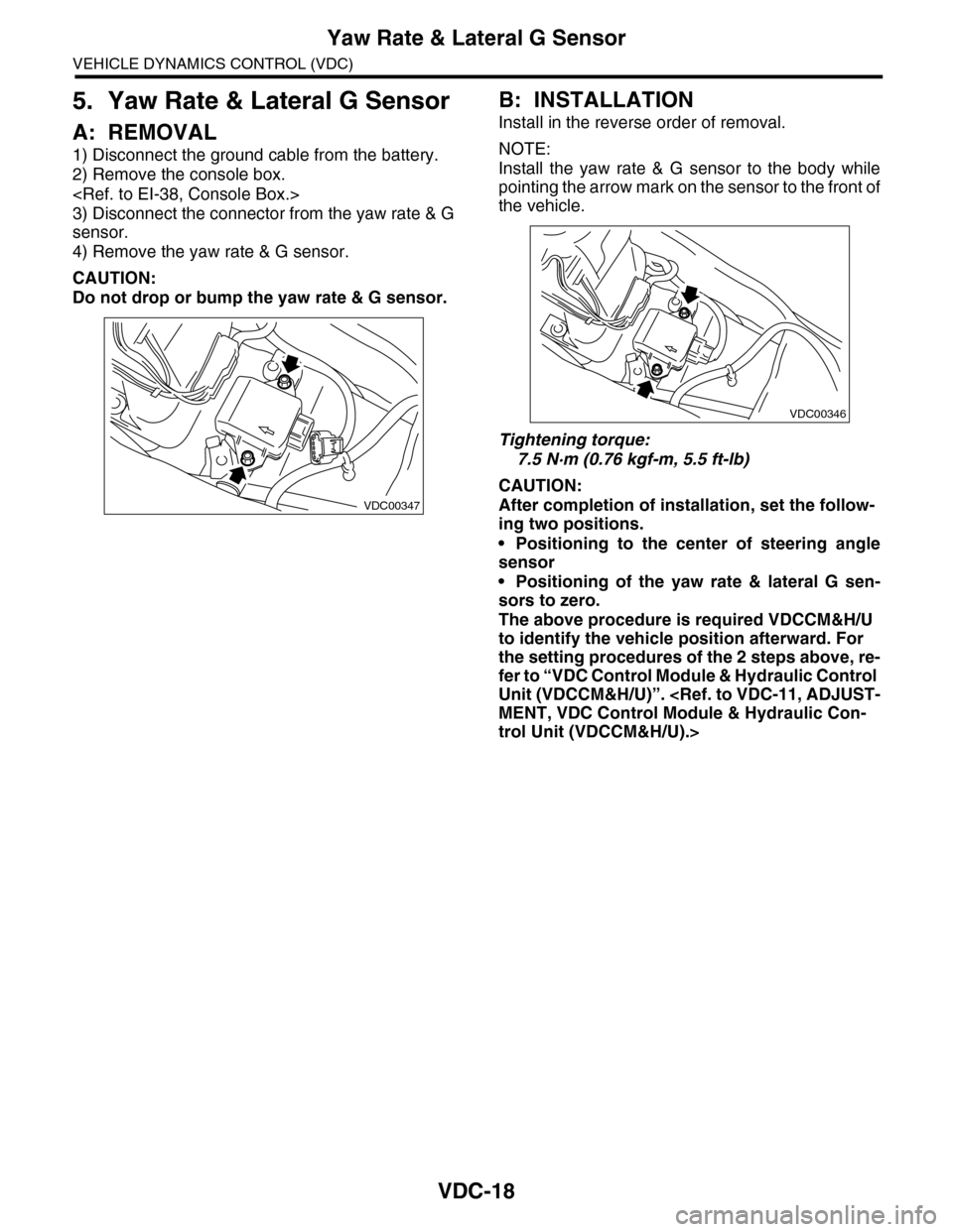
1) Disconnect the ground cable from the battery.
2) Remove the console box.
3) Disconnect the connector from the yaw rate & G
sensor.
4) Remove the yaw rate & G sensor.
CAUTION:
Do not drop or bump the yaw rate & G sensor.
B: INSTALLATION
Install in the reverse order of removal.
NOTE:
Install the yaw rate & G sensor to the body while
pointing the arrow mark on the sensor to the front of
the vehicle.
Tightening torque:
7.5 N·m (0.76 kgf-m, 5.5 ft-lb)
CAUTION:
After completion of installation, set the follow-
ing two positions.
•Positioning to the center of steering angle
sensor
•Positioning of the yaw rate & lateral G sen-
sors to zero.
The above procedure is required VDCCM&H/U
to identify the vehicle position afterward. For
the setting procedures of the 2 steps above, re-
fer to “VDC Control Module & Hydraulic Control
Unit (VDCCM&H/U)”.
MENT, VDC Control Module & Hydraulic Con-
trol Unit (VDCCM&H/U).>
VDC00347
VDC00346
Page 1102 of 2453

VDC-21
Front ABS Wheel Speed Sensor
VEHICLE DYNAMICS CONTROL (VDC)
7. Front ABS Wheel Speed Sen-
sor
A: REMOVAL
1) Disconnect the ground cable from the battery.
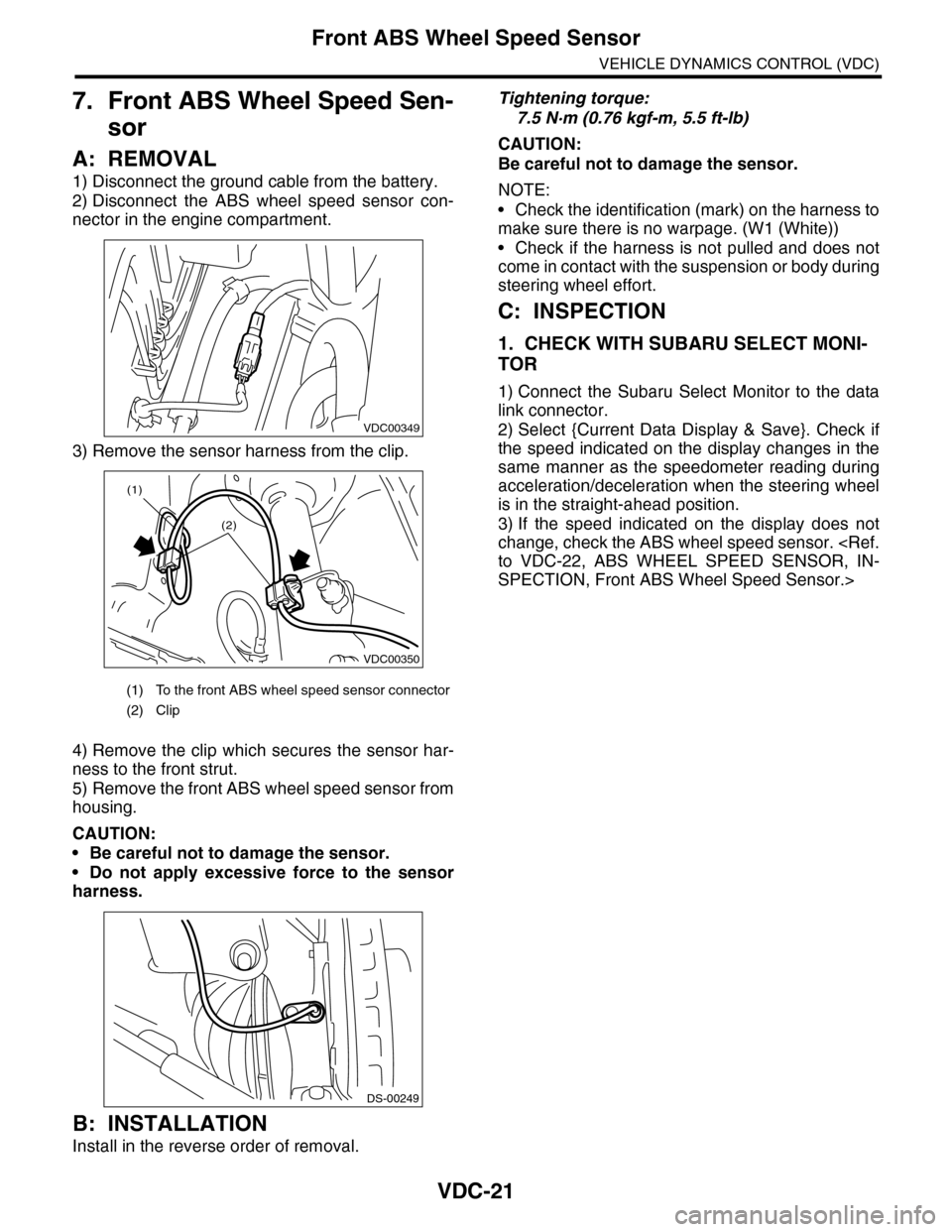
2) Disconnect the ABS wheel speed sensor con-
nector in the engine compartment.
3) Remove the sensor harness from the clip.
4) Remove the clip which secures the sensor har-
ness to the front strut.
5) Remove the front ABS wheel speed sensor from
housing.
CAUTION:
•Be careful not to damage the sensor.
•Do not apply excessive force to the sensor
harness.
B: INSTALLATION
Install in the reverse order of removal.
Tightening torque:
7.5 N·m (0.76 kgf-m, 5.5 ft-lb)
CAUTION:
Be careful not to damage the sensor.
NOTE:
•Check the identification (mark) on the harness to
make sure there is no warpage. (W1 (White))
•Check if the harness is not pulled and does not
come in contact with the suspension or body during
steering wheel effort.
C: INSPECTION
1. CHECK WITH SUBARU SELECT MONI-
TOR
1) Connect the Subaru Select Monitor to the data
link connector.
2) Select {Current Data Display & Save}. Check if
the speed indicated on the display changes in the
same manner as the speedometer reading during
acceleration/deceleration when the steering wheel
is in the straight-ahead position.
3) If the speed indicated on the display does not
change, check the ABS wheel speed sensor.
to VDC-22, ABS WHEEL SPEED SENSOR, IN-
SPECTION, Front ABS Wheel Speed Sensor.>
(1) To the front ABS wheel speed sensor connector
(2) Clip
VDC00349
VDC00350
(1)
(2)
DS-00249
Page 1104 of 2453
VDC-23
Rear ABS Wheel Speed Sensor
VEHICLE DYNAMICS CONTROL (VDC)
8. Rear ABS Wheel Speed Sen-
sor
A: REMOVAL
1) Disconnect the ground cable from the battery.
2) Disconnect the connector from the rear ABS
wheel speed sensor.
3) Remove the sensor harness from the rear arm
clip.
4) Remove the rear ABS wheel speed sensor from
the rear housing.
CAUTION:
•Be careful not to damage the sensor.
•Do not apply excessive force to the sensor
harness.
B: INSTALLATION
Install in the reverse order of removal.
CAUTION:
Be careful not to damage the sensor.
Tightening torque:
7.5 N·m (0.76 kgf-m, 5.5 ft-lb)
NOTE:
Check the identification (mark) on the harness to
make sure there is no warpage. (W3 (White))
C: INSPECTION
1. ABS WHEEL SPEED SENSOR
INSPECTION, Front ABS Wheel Speed Sensor.>
VDC00351
VDC00352
DS-00363
Page 1107 of 2453
VDC-26
TCS OFF Switch
VEHICLE DYNAMICS CONTROL (VDC)
11.TCS OFF Switch
A: REMOVAL
1) Remove the instrument panel lower cover.
2) Remove the screws, and then remove the TCS
OFF switch.
B: INSTALLATION
Install in the reverse order of removal.
C: INSPECTION
Measure the resistance between the VDC OFF
switch terminals.
If NG, replace the TCS OFF switch.
Switch position Terminal No. Standard
OFF 2 — 15 1 M Ω or more
ON 2 — 15 Less than 1 Ω
VDC00240
765432115141312111098