Page 835 of 2453

DS-18
Rear Axle
DRIVE SHAFT SYSTEM
B: INSTALLATION
NOTE:
•Be sure to use a new self-locking nut.
•Always tighten the stabilizer bushing in the state
where the vehicle is at curb weight and the wheels
are in full contact with the ground.
Install in the reverse order of removal.
Tightening torque:
Refer to COMPONENT of General Description
for tightening torque.
scription.>
scription.>
scription.>
scription.>
scription.>
C: DISASSEMBLY
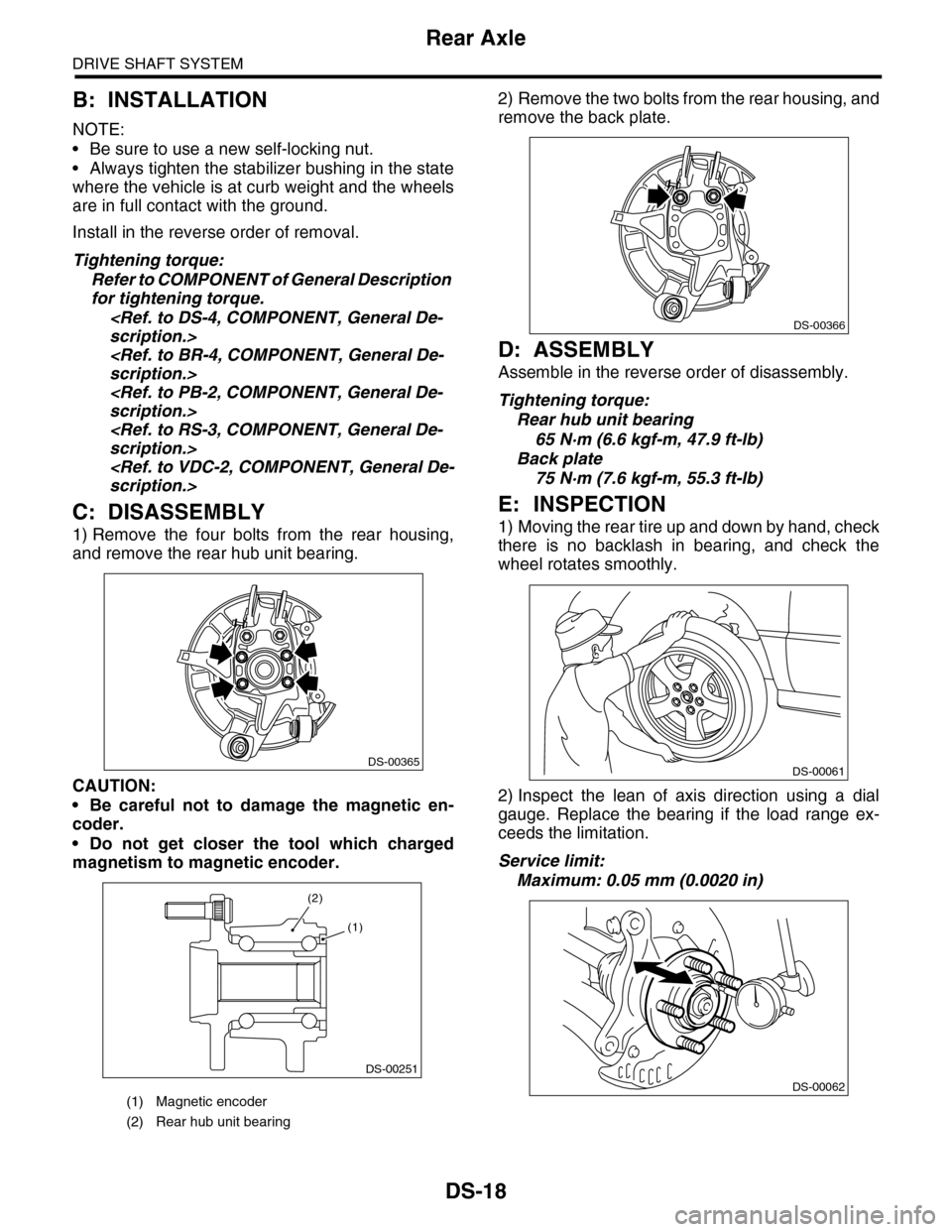
1) Remove the four bolts from the rear housing,
and remove the rear hub unit bearing.
CAUTION:
•Be careful not to damage the magnetic en-
coder.
•Do not get closer the tool which charged
magnetism to magnetic encoder.
2) Remove the two bolts from the rear housing, and
remove the back plate.
D: ASSEMBLY
Assemble in the reverse order of disassembly.
Tightening torque:
Rear hub unit bearing
65 N·m (6.6 kgf-m, 47.9 ft-lb)
Back plate
75 N·m (7.6 kgf-m, 55.3 ft-lb)
E: INSPECTION
1) Moving the rear tire up and down by hand, check
there is no backlash in bearing, and check the
wheel rotates smoothly.
2) Inspect the lean of axis direction using a dial
gauge. Replace the bearing if the load range ex-
ceeds the limitation.
Service limit:
Maximum: 0.05 mm (0.0020 in)
(1) Magnetic encoder
(2) Rear hub unit bearing
DS-00365
DS-00251
(2)
(1)
DS-00366
DS-00061
DS-00062
Page 861 of 2453
FS-13
Front Crossmember Support Plate
FRONT SUSPENSION
3. Front Crossmember Support
Plate
A: REMOVAL
1) Lift-up the vehicle.
2) Remove the front under cover.
REMOVAL, Front Under Cover.>
3) Remove the bolt and remove front crossmember
support plate.
B: INSTALLATION
Install in the reverse order of removal.
Tightening torque:
Crossmember support plate:
60 N·m (6.1 kgf-m, 44.3 ft-lb)
Jack-up plate:
60 N·m (6.1 kgf-m, 44.3 ft-lb)
(1) Crossmember support plate
(2) Jack–up plate
(2)(1)
(1)
FS-00200
Page 862 of 2453
FS-14
Front Stabilizer
FRONT SUSPENSION
4. Front Stabilizer
A: REMOVAL
1) Lift-up the vehicle, and then remove the front
wheels.
2) Remove the front under cover.
REMOVAL, Front Under Cover.>
3) Remove the front crossmember support plate.
Support Plate.>
4) Remove the stabilizer link.
5) Remove the stabilizer link.
B: INSTALLATION
Install in the reverse order of removal.
NOTE:
•Use a new flange nut (with WAX).
•Install so that the paint mark on the stabilizer is
on the left side of the vehicle.
•Install the stabilizer bushing (front crossmember
side) while aligning it with the paint mark on stabi-
lizer.
Tightening torque:
Stabilizer link:
60 N·m (6.1 kgf-m, 44.3 ft-lb)
Stabilizer clamp
25 N·m (2.5 kgf-m, 18.1 ft-lb)
C: INSPECTION
1) Check the bushing for cracks, fatigue or dam-
age.
2) Check the stabilizer link for damage.
FS-00214
FS-00202
Page 865 of 2453
FS-17
Front Arm
FRONT SUSPENSION
C: DISASSEMBLY
1. FRONT BUSHING
Using the ST and a press, remove the front bush-
ing.
ST 927680000 INSTALLER & REMOVER
SET
2. REAR BUSHING
1) Put an alignment mark on the front arm based on
the center of rear bushing recess portion.
CAUTION:
Always put an alignment mark for aligning the
position on bushing installation.
2) Using the ST and a press, remove the rear bush-
ing.
ST1 REMOVER
ST2 BASE
D: ASSEMBLY
1. FRONT BUSHING
Assemble in the reverse order of disassembly.
CAUTION:
Install the front bushing in proper direction as
shown in the figure.
(1) Put an alignment mark.
(2) Recess portion (wide spacing)
(3) Recess portion (narrow spacing)
ST
FS-00204
FS-00215
(2)
(1)
(1)(3)
(1) Press
(2) Front arm
(3) Rear bushing
(1) Face the bushing toward the center of ball joint.
(2) Ball joint
(3)±3°
(1)
(2)
(3)
ST2
ST1
FS-00126
FS-00102
(1)
(2)
(3)
Page 871 of 2453

FS-23
Front Crossmember
FRONT SUSPENSION
8. Front Crossmember
A: REMOVAL
1) Lift-up the vehicle, and then remove the front
wheels.
2) Remove the front exhaust pipe.
3) Remove the front crossmember support plate.
Support Plate.>
4) Remove the front stabilizer.
MOVAL, Front Stabilizer.>
5) Disconnect the tie-rod end from housing.
6) Remove the front arm.
AL, Front Arm.>
7) Remove the nuts attaching the engine mount
cushion rubber to crossmember.
8) Remove the steering universal joint.
9) Disconnect the power steering hose from steer-
ing gearbox.
10) Lift the engine approx. 10 mm (0.39 in) using
the chain block.
11) Support the crossmember with a jack, remove
the bolts securing crossmember to body, and then
gradually lower the crossmember with steering
gearbox as a unit.
CAUTION:
When removing the crossmember downward,
be careful that the tie-rod end does not interfere
with drive shaft boot.
B: INSTALLATION
1) Install in the reverse order of removal.
NOTE:
•Use a new bolt and self-locking nut. For parts
which are not reusable, refer to “COMPONENT”.
tion.>
•Always tighten the stabilizer bushing in the state
where the vehicle is at curb weight and the wheels
are in full contact with the ground.
Tightening torque:
Crossmember to body:
95 N·m (9.7 kgf-m, 70.1 ft-lb)
Engine mounting to Crossmember:
85 N·m (8.7 kgf-m, 62.7 ft-lb)
Front arm to Crossmember:
95 N·m (9.7 kgf-m, 70.1 ft-lb)
Front arm to Support plate:
145 N·m (14.8 kgf-m, 106.9 ft-lb)
Support plate to Body:
150 N·m (15.3 kgf-m, 110.6 ft-lb)
Tie–rod end to housing:
27.0 N·m (2.75 kgf-m, 19.9 ft-lb)
After tightening to the specified torque, tighten the
castle nut further but within 60° until the hole in the
ball stud is aligned with a slot in castle nut
Universal joint:
24 N·m (2.4 kgf-m, 17.4 ft-lb)
Stabilizer clamp
25 N·m (2.5 kgf-m, 18.1 ft-lb)
Stabilizer link:
60 N·m (6.1 kgf-m, 44.3 ft-lb)
Power steering hose to Steering gearbox:
15 N·m (1.5 kgf-m, 11 ft-lb)
2) Purge air from the power steering system.
3) Inspect the wheel alignment and adjust if neces-
sary.
C: INSPECTION
Check the crossmember for wear, damage or
cracks, and then repair or replace if faulty.
FS-00209
FS-00119
Page 875 of 2453

PB-4
Parking Brake Pedal
PARKING BRAKE
2. Parking Brake Pedal
A: REMOVAL
1) Set the wheel stoppers to tires.
2) Remove the instrument panel lower cover.
to EI-36, REMOVAL, Instrument Panel Lower Cov-
er.>
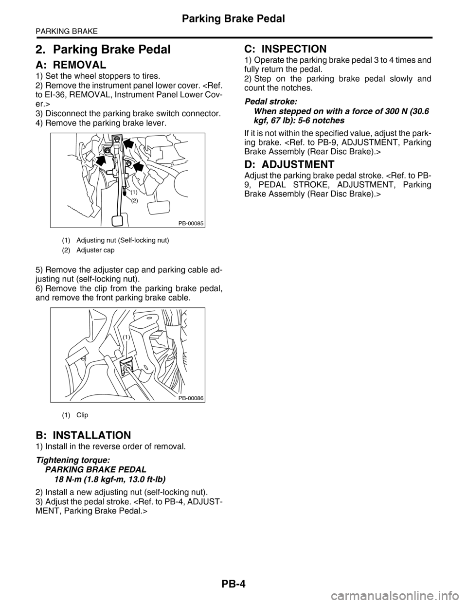
3) Disconnect the parking brake switch connector.
4) Remove the parking brake lever.
5) Remove the adjuster cap and parking cable ad-
justing nut (self-locking nut).
6) Remove the clip from the parking brake pedal,
and remove the front parking brake cable.
B: INSTALLATION
1) Install in the reverse order of removal.
Tightening torque:
PARKING BRAKE PEDAL
18 N·m (1.8 kgf-m, 13.0 ft-lb)
2) Install a new adjusting nut (self-locking nut).
3) Adjust the pedal stroke.
MENT, Parking Brake Pedal.>
C: INSPECTION
1) Operate the parking brake pedal 3 to 4 times and
fully return the pedal.
2) Step on the parking brake pedal slowly and
count the notches.
Pedal stroke:
When stepped on with a force of 300 N (30.6
kgf, 67 lb): 5-6 notches
If it is not within the specified value, adjust the park-
ing brake.
Brake Assembly (Rear Disc Brake).>
D: ADJUSTMENT
Adjust the parking brake pedal stroke.
9, PEDAL STROKE, ADJUSTMENT, Parking
Brake Assembly (Rear Disc Brake).>
(1) Adjusting nut (Self-locking nut)
(2) Adjuster cap
(1) Clip
PB-00085
(1)
(2)
PB-00086
(1)
Page 877 of 2453
PB-6
Parking Brake Cable
PARKING BRAKE
5) Lift-up the vehicle, and then remove the rear
wheels.
6) Remove the rear parking brake cable from the
rear brake.
Brake Assembly (Rear Disc Brake).>
7) Remove the cable clamp, and remove the park-
ing brake cable from the guide.
8) Remove the cable clamp from rear floor.
9) Remove the cable assembly.
B: INSTALLATION
1) Install in the reverse order of removal.
2) Adjust the parking brake pedal stroke.
PB-4, ADJUSTMENT, Parking Brake Pedal.>
Tightening torque:
scription.>
C: INSPECTION
Check and replace the removed cable if damaged,
rusty or faulty.
1) Check the cable for smooth operation.
2) Check the front parking brake cable for damage
and rust.
3) Check the rear parking brake cable for damage,
bends and cracks.
4) Check the boot for damage, cracks, and corro-
sion.
(1) Guide
PB-00090(1)
PB-00091
Page 879 of 2453

PB-8
Parking Brake Assembly (Rear Disc Brake)
PARKING BRAKE
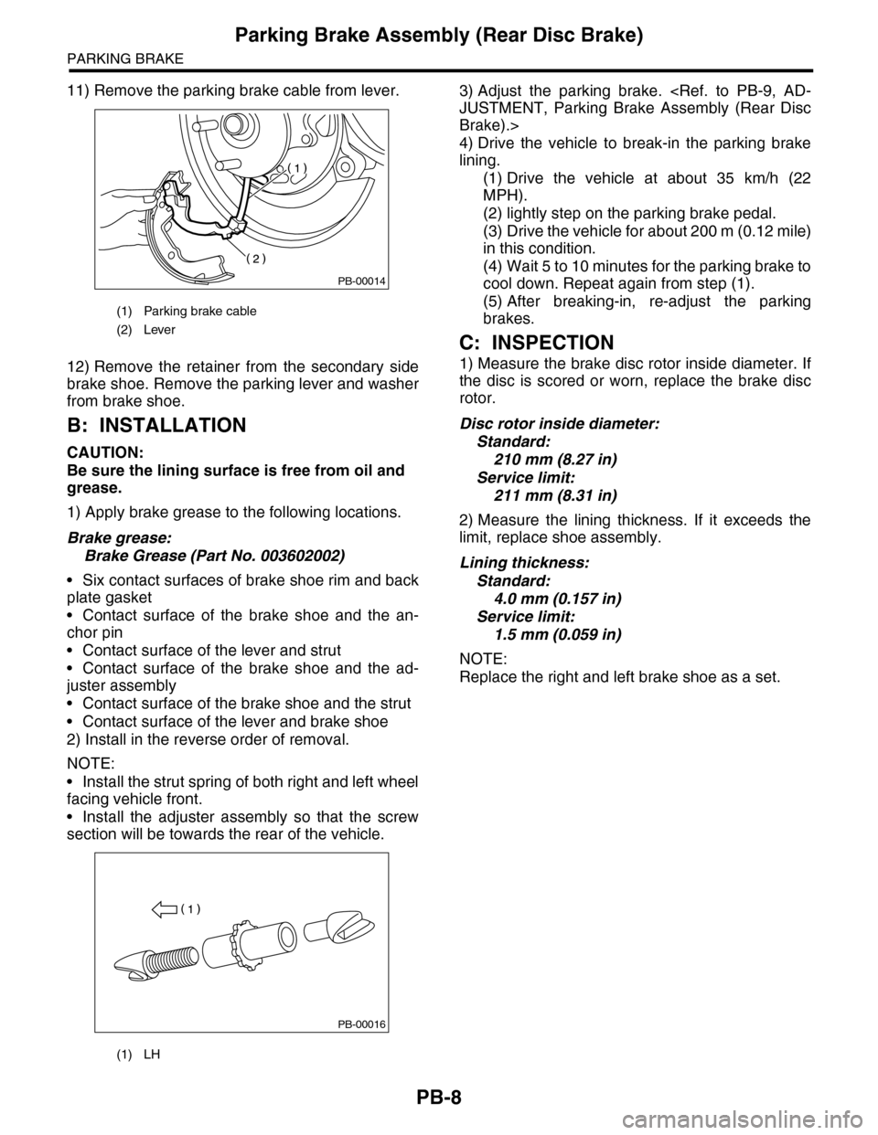
11) Remove the parking brake cable from lever.
12) Remove the retainer from the secondary side
brake shoe. Remove the parking lever and washer
from brake shoe.
B: INSTALLATION
CAUTION:
Be sure the lining surface is free from oil and
grease.
1) Apply brake grease to the following locations.
Brake grease:
Brake Grease (Part No. 003602002)
•Six contact surfaces of brake shoe rim and back
plate gasket
•Contact surface of the brake shoe and the an-
chor pin
•Contact surface of the lever and strut
•Contact surface of the brake shoe and the ad-
juster assembly
•Contact surface of the brake shoe and the strut
•Contact surface of the lever and brake shoe
2) Install in the reverse order of removal.
NOTE:
•Install the strut spring of both right and left wheel
facing vehicle front.
•Install the adjuster assembly so that the screw
section will be towards the rear of the vehicle.
3) Adjust the parking brake.
JUSTMENT, Parking Brake Assembly (Rear Disc
Brake).>
4) Drive the vehicle to break-in the parking brake
lining.
(1) Drive the vehicle at about 35 km/h (22
MPH).
(2) lightly step on the parking brake pedal.
(3) Drive the vehicle for about 200 m (0.12 mile)
in this condition.
(4) Wait 5 to 10 minutes for the parking brake to
cool down. Repeat again from step (1).
(5) After breaking-in, re-adjust the parking
brakes.
C: INSPECTION
1) Measure the brake disc rotor inside diameter. If
the disc is scored or worn, replace the brake disc
rotor.
Disc rotor inside diameter:
Standard:
210 mm (8.27 in)
Service limit:
211 mm (8.31 in)
2) Measure the lining thickness. If it exceeds the
limit, replace shoe assembly.
Lining thickness:
Standard:
4.0 mm (0.157 in)
Service limit:
1.5 mm (0.059 in)
NOTE:
Replace the right and left brake shoe as a set.
(1) Parking brake cable
(2) Lever
(1) LH
PB-00014
PB-00016