Page 2282 of 2453
CS-30
AT Shift Lock Solenoid and “P” Range Switch
CONTROL SYSTEMS
5) Disconnect the terminal of AT shift lock solenoid
from the connector, using a flat-tip screwdriver.
B: INSTALLATION
NOTE:
For installation of the mode change switch and the
shift button switch, refer to the section on Select
Levers.
ver.>
1. “P” RANGE SWITCH
Install in the reverse order of removal.
NOTE:
Connect the “P” range switch terminal to connector.
2. AT SHIFT LOCK SOLENOID
Install in the reverse order of removal.
NOTE:
Connect the AT shift lock solenoid switch terminal
to connector.
(A) AT shift lock solenoid
(A) “P” range switch (wire color: Red)
CS-00649
5432112 11 10 9876
(A)
CS-00646
5432112 11 10 9876
(A)
(A) AT shift lock solenoid (color code: Black)
(B) AT shift lock solenoid (wire color: Blue)
CS-00651
5432112 11 10 9876
(A) (B)
Page 2287 of 2453
WI-3
Basic Diagnostic Procedure
WIRING SYSTEM
1. Basic Diagnostic Procedure
A: BASIC PROCEDURES
1. GENERAL DESCRIPTION
The most important purpose of diagnostics is to
quickly determine which part is malfunctioning, to
save time and labor.
2. IDENTIFICATION OF TROUBLE SYMP-
TOM
Determine what the problem is based on the symp-
tom.
3. PROBABLE CAUSE OF TROUBLE
Look at the wiring diagram and check the system’s
circuit. Then check the switch, relay, fuse, ground,
etc.
4. LOCATION AND REPAIR OF TROUBLE
1) Using the diagnostics, narrow down the causes.
2) If necessary, use a voltmeter, ohmmeter, etc.
3) Before replacing certain component parts
(switch, relay, etc.), check the power supply,
ground, for open wiring harness, poor connectors,
etc. If no problem is encountered, check the com-
ponent parts.
5. SYSTEM OPERATION CHECK
After repairing, ensure that the system operates
properly.
B: BASIC INSPECTION
1. VOLTAGE MEASUREMENT
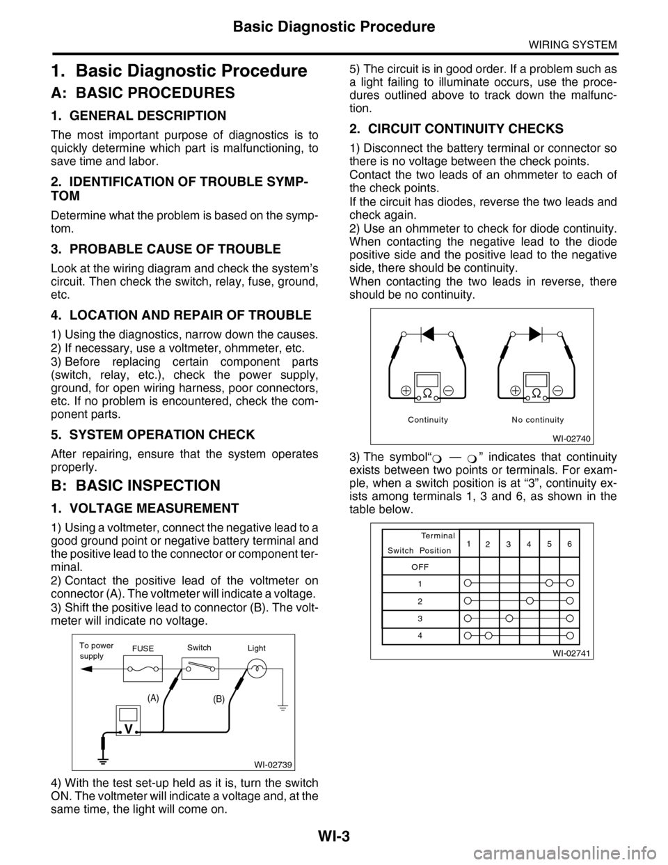
1) Using a voltmeter, connect the negative lead to a
good ground point or negative battery terminal and
the positive lead to the connector or component ter-
minal.
2) Contact the positive lead of the voltmeter on
connector (A). The voltmeter will indicate a voltage.
3) Shift the positive lead to connector (B). The volt-
meter will indicate no voltage.
4) With the test set-up held as it is, turn the switch
ON. The voltmeter will indicate a voltage and, at the
same time, the light will come on.
5) The circuit is in good order. If a problem such as
a light failing to illuminate occurs, use the proce-
dures outlined above to track down the malfunc-
tion.
2. CIRCUIT CONTINUITY CHECKS
1) Disconnect the battery terminal or connector so
there is no voltage between the check points.
Contact the two leads of an ohmmeter to each of
the check points.
If the circuit has diodes, reverse the two leads and
check again.
2) Use an ohmmeter to check for diode continuity.
When contacting the negative lead to the diode
positive side and the positive lead to the negative
side, there should be continuity.
When contacting the two leads in reverse, there
should be no continuity.
3) The symbol“ — ” indicates that continuity
exists between two points or terminals. For exam-
ple, when a switch position is at “3”, continuity ex-
ists among terminals 1, 3 and 6, as shown in the
table below.
WI-02739
To powerFUSEsupplySwitchLight
V
(A)(B)
WI-02740
Continuity No continuity
�
Page 2343 of 2453
WI-59
TPM Control System
WIRING SYSTEM
9. TPM Control System
A: WIRING DIAGRAM
WI-08065
TPM-01TPM-01
DIAGNOSISCONNECTOR
TMP CONTROL MODULE
COMBINATIONMETER
REVERSE CIRCUIT
TIRE INFLATIONPRESSURE WARNING LIGHT
3
1315
A10
642
1310
18
C4
RRYGBWL
5
GY
GY
RRY
RY
P
P
V
PV
i102
R167
i10A:
R2
B97
B97
R2
i80
i81
DATA LINK CONNECTOR
B402
R211
BY
9
BY33
YL
8
YL
GB
VDCCONTROLMODULE
B310
GYW
FB-32F/B FUSE NO. 4(IG)
TO POWER SUPPLY CIRCUIT
B281C:
BODYINTEGRATED UNIT
PVR
REF. TO GROUNDCIRCUIT [GND-05]
REF. TO ENGINE ELECTRICALSYSTEM [E/G-05]
BY
REF. TO GROUNDCIRCUIT [GND-05]
B97
234 567891112 13 14 17 18 19 201101516
B281C:
56782194310242223 25111213141526 27 281617181920 21
FB-36F/B FUSE NO. 5(IG)
FB-17F/B FUSE NO. 7(B)
FB-48F/B FUSE NO. 4(IG)
FB-27M/B FUSE NO. 13(B)
GY
W
VR
BL
BL
B402
123 8910413 14 15 165671112
WL
JOINTCONNECTOR
R224
R225
4*
2*
GBGB
JOINT CONNECTOR
R224R225
1*1*
BrWWL
A3A4
BrWBrW
JOINTCONNECTOR
i126
i127
5*
3*3*
: TERMINAL NO. OPTIONAL ARRANGEMENT BETWEEN 1 AMD 2
2*
: TERMINAL NO. OPTIONAL ARRANGEMENT AMONG 7, 8 AND 9
3*
: TERMINAL NO. OPTIONAL ARRANGEMENT BETWEEN 5 AND 6
4*
: TERMINAL NO. OPTIONAL ARRANGEMENT AMONG 10, 11 AND 12
5*
: TERMINAL NO. OPTIONAL ARRANGEMENT BETWEEN 9 AND 10
1*
123456789101112
i126(BLACK)
i127(BLACK)
R211
R224
R225
B310
i10
19 20 2115 16 17 182223242526272829301234568910 11 12 13 147
A:1234
1516171819202122232425262728293031323334353637383940414245464344568910 11 12 13 147
1234567891413121110151617181920
i102(BLUE)
9
1
10
12
13
(BLACK)
(GREEN)
(BLACK)
Page 2345 of 2453
WI-61
Vehicle Dynamics Control System
WIRING SYSTEM
WI-08067
VDC-02VDC-02
VDCWARNINGLIGHT/TCS OFFINDICATORLIGHT
A16
BY
A15
BYPV
BY
COMBINATIONMETER
MICRO COMPUTER
CAN TRANSCEIVER& RECEIVER
FB-36F/B FUSE NO. 5(IG)
TO POWER SUPPLY CIRCUIT
I/F
i10A:
i11B:
GW
16
YL
33
LgR
3
PARKING BRAKE/BRAKE FLUID LEVELWARNING LIGHTABS WARNING
LIGHT
B8
17
LgB
18
LgR
GWLgR
B6
LgRLgB
i3
B38
REVERSECIRCUITREVERSECIRCUIT
VDC CONTROL MODULE
B310
OPCONNECTORB228
YL5
VDCOPERATIONINDICATORLIGHT
B228
131415
123456789101112
DRIVER
REF. TO GROUNDCIRCUIT [GND-05]
A29A30
REF. TO ENGINEELECTRICAL SYSTEM[E/G-03]
REF. TO CANCOMMUNICATIONSYSTEM [CAN-01]
B38
1234 567891011 1213 14 15 16 17 18 19 20123456789101112
i126(BLACK) (GREEN)(GREEN)
i127(BLACK)
(BLACK)
BrW
A3A4
BrWBrW
BrW
JOINT CONNECTOR
i126i127
1*
2*2*
: TERMINAL NO. OPTIONAL ARRANGEMENT AMONG 7, 8 AND 9
2*
: TERMINAL NO. OPTIONAL ARRANGEMENT AMONG 10, 11 AND 12
1*
B310
i10
19 20 2115 16 17 182223242526272829301234568910 11 12 13 147
A:
1234
1516171819202122232425262728293031323334353637383940414245464344568910 11 12 13 147
i11
123 45678910 11 12 13 14
B:
Page 2353 of 2453
WI-69
Airbag System
WIRING SYSTEM
WI-08075
AB-02AB-02WL
FB-17F/B FUSE NO.7(B)
TO POWER SUPPLY CIRCUIT
BrW
A3
BrW
A4
REVERSECIRCUITPOWER SUPPLY CIRCUIT
MICRO COMPUTERAIRBAGWARNINGLIGHT
13
1
B12A15
LgBY
A16
BY
Lg
3
AIRBAG CONTROL MODULEAB6
i2
B403
B31
AB1
BrW
Lg
123456789101112
JOINTCONNECTOR
i127
i126
WL
A1
WL
A2
JOINT CONNECTOR
i125
i124i102R167
BY
REF. TO GROUNDCIRCUIT [GND-05]
JOINT CONNECTOR
R224
WLWLWLWL5
FB-36F/B FUSE NO.5(IG)
: TERMINAL NO. OPTIONAL ARRANGEMENT AMONG 7, 8 AND 9: TERMINAL NO. OPTIONAL ARRANGEMENT AMONG 10, 11 AND 12
1*
1*
2*2*
3*2*
1*1*
3*
2*
: TERMINAL NO. OPTIONAL ARRANGEMENT BETWEEN 5 AND 63*
COMBINATION METER
i10A:
i11B:
(YELLOW)AB1
AB6
1234567891011121314161715
1819202122232425262728
123456789101112
i126(BLACK)
i125(GRAY)
i124(GRAY)R224
i127(GRAY)
B283
A:
345678910
16 17 18 19 20
121112132425262122231415
B282
B:
12345678
910 1112 1314 1516
1234567891413121110151617181920
i102(BLUE)
567821943
10
2422 23 25
11121314151617181920 21
B403
i11
123 45678910 11 12 13 14
B:
i10
19 20 2115 16 17 182223242526272829301234568910 11 12 13 147
A:
Page 2416 of 2453
WI-132
Combination Meter System
WIRING SYSTEM
WI-08134
METER-02METER-02
ECM
TPM
CONTROL M
ODULE
VDC CONTROL M
ODULE
OIL P
RESSURE SW
ITCH
GENERATOR
BRAKE FLU
ID LEV
EL SWITCH
AIRBAG WARNING LIGHT
HEADLIGHT RELAYAIRBAG CONTROLMODULE
ABS WARNING LIGHT
CHARGE WARNING LIGHTPARKING BRAKE/BRAKE FLUIDLEVEL WARNING LIGHT
VDC CONTROL M
ODULE
PARKING BRAKE SWITCH
REAR DIFFE
RENTIAL
PRESSURE SWITCH
SEA
T BELT W
ARNING LIG
HT
SEAT BELT S
WITCH
A3
IGNITION SWITCH (IG)
A4
REVERSECIRCUIT
OIL PRESSUREWARNING LIGHT
MALFUNCTION INDICATOR LIGHT
HI-BEAM INDICATOR LIGHT
TURN SIGNAL &HAZARD MODULE
TURN SIGNALINDICATOR LIGHT LHTURN SIGNALINDICATOR LIGHT RH
REVERSECIRCUIT
REVERSECIRCUIT
B
B3A14B1B12
METER-03A
BATTERY
B8B7B9B6B10B5B4B11
REAR DIFFERENTIAL OIL TEMPERATURE WARNING LIGHT
REVERSECIRCUIT
DIMMER SWITCH
TIRE INFLATION PRESSURE WARNING LIGHT
REVERSECIRCUIT
A10A7
Page 2422 of 2453
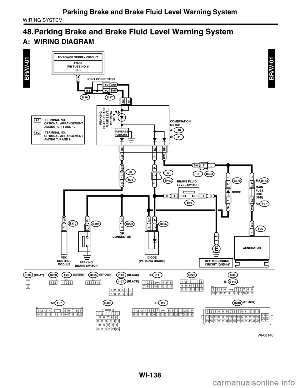
WI-138
Parking Brake and Brake Fluid Level Warning System
WIRING SYSTEM
48.Parking Brake and Brake Fluid Level Warning System
A: WIRING DIAGRAM
BR/W-01BR/W-01
WI-08140
COMBINATIONMETERPRAKINGBRAKE/BRAKEFLUID LEVELWARNINGLIGHT
12
P
18
21
B9
BW
B7
PLgR
PLgR
B8
A: i10
B: i11
LgR
B
GENERATOR
MAINFUSEBOX(M/B)
DIODE
WB
1F26
REVERSECIRCUIT
L
WB
A7
B11
F37
B143B370B:
A:
BWL
PB21
3
LgRB310Gr
PARKINGBRAKE SWITCH
DIODE(PARKING BRAKE)
B404
B16
B228B405Gr
8
P
3
Gr
4
OPCONNECTOR
BRAKE FLUIDLEVEL SWITCH
L
Gr
1
2
B143
1234 567891011 1213 14 15 16 17 18 19 20
B403B310
B16
12
B405
1234
B228
131415
123456789101112
F26
123
B370
12
F37A:
1234 5678910 11 12 13 14 15 16 17 18 19 20
B:
B38
REF. TO GROUNDCIRCUIT [GND-03]
i3
B38
FB-36F/B FUSE NO. 5(IG)
TO POWER SUPPLY CIRCUIT
BrW
A3A4
BrW
BrW
JOINT CONNECTOR
i126i127
1*
2*2*
: TERMINAL NO. OPTIONAL ARRANGEMENT AMONG 7, 8 AND 9
2*
: TERMINAL NO. OPTIONAL ARRANGEMENT AMONG 10, 11 AND 12
1*
i11
123 45678910 11 12 13 14
B:
i10
19 20 2115 16 17 182223242526272829301234568910 11 12 13 147
A:
1234
1516171819202122232425262728293031323334353637383940414245464344568910 11 12 13 147
VDCCONTROLMODULE
i2
B403
i2B403
567821943
10
2422 23 25
11121314151617181920 21
(GRAY)(GREEN) (BROWN)
(BLACK)
123456789101112
i126(BLACK)
i127(BLACK)