2009 SUBARU TRIBECA Reverse
[x] Cancel search: ReversePage 2108 of 2453
5AT-92
AT Main Case
AUTOMATIC TRANSMISSION
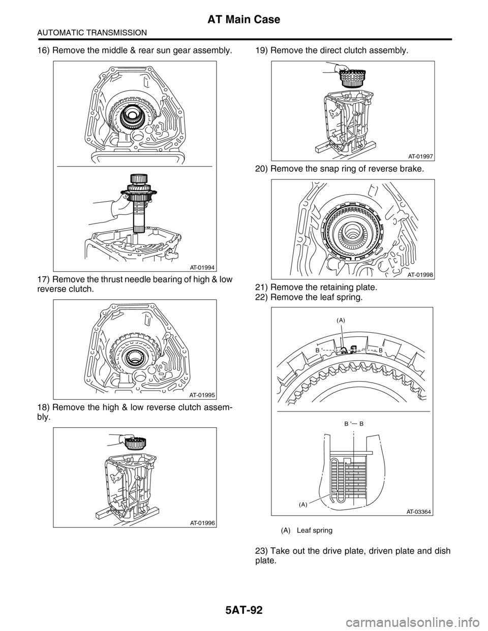
16) Remove the middle & rear sun gear assembly.
17) Remove the thrust needle bearing of high & low
reverse clutch.
18) Remove the high & low reverse clutch assem-
bly.
19) Remove the direct clutch assembly.
20) Remove the snap ring of reverse brake.
21) Remove the retaining plate.
22) Remove the leaf spring.
23) Take out the drive plate, driven plate and dish
plate.
AT-01994
AT-01995
AT-01996(A) Leaf spring
AT-01997
AT-01998
B'B
B' B
(A)
(A)AT-03364
Page 2109 of 2453
5AT-93
AT Main Case
AUTOMATIC TRANSMISSION
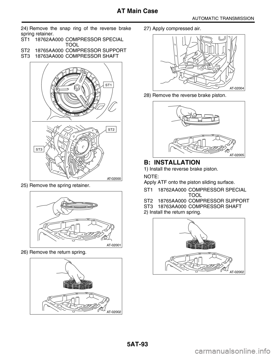
24) Remove the snap ring of the reverse brake
spring retainer.
ST1 18762AA000 COMPRESSOR SPECIAL
TOOL
ST2 18765AA000 COMPRESSOR SUPPORT
ST3 18763AA000 COMPRESSOR SHAFT
25) Remove the spring retainer.
26) Remove the return spring.
27) Apply compressed air.
28) Remove the reverse brake piston.
B: INSTALLATION
1) Install the reverse brake piston.
NOTE:
Apply ATF onto the piston sliding surface.
ST1 18762AA000 COMPRESSOR SPECIAL
TOOL
ST2 18765AA000 COMPRESSOR SUPPORT
ST3 18763AA000 COMPRESSOR SHAFT
2) Install the return spring.
AT-02000
ST3
ST2
ST1
AT-02001
AT-02002
AT-02004
AT-02005
AT-02002
Page 2110 of 2453
5AT-94
AT Main Case
AUTOMATIC TRANSMISSION
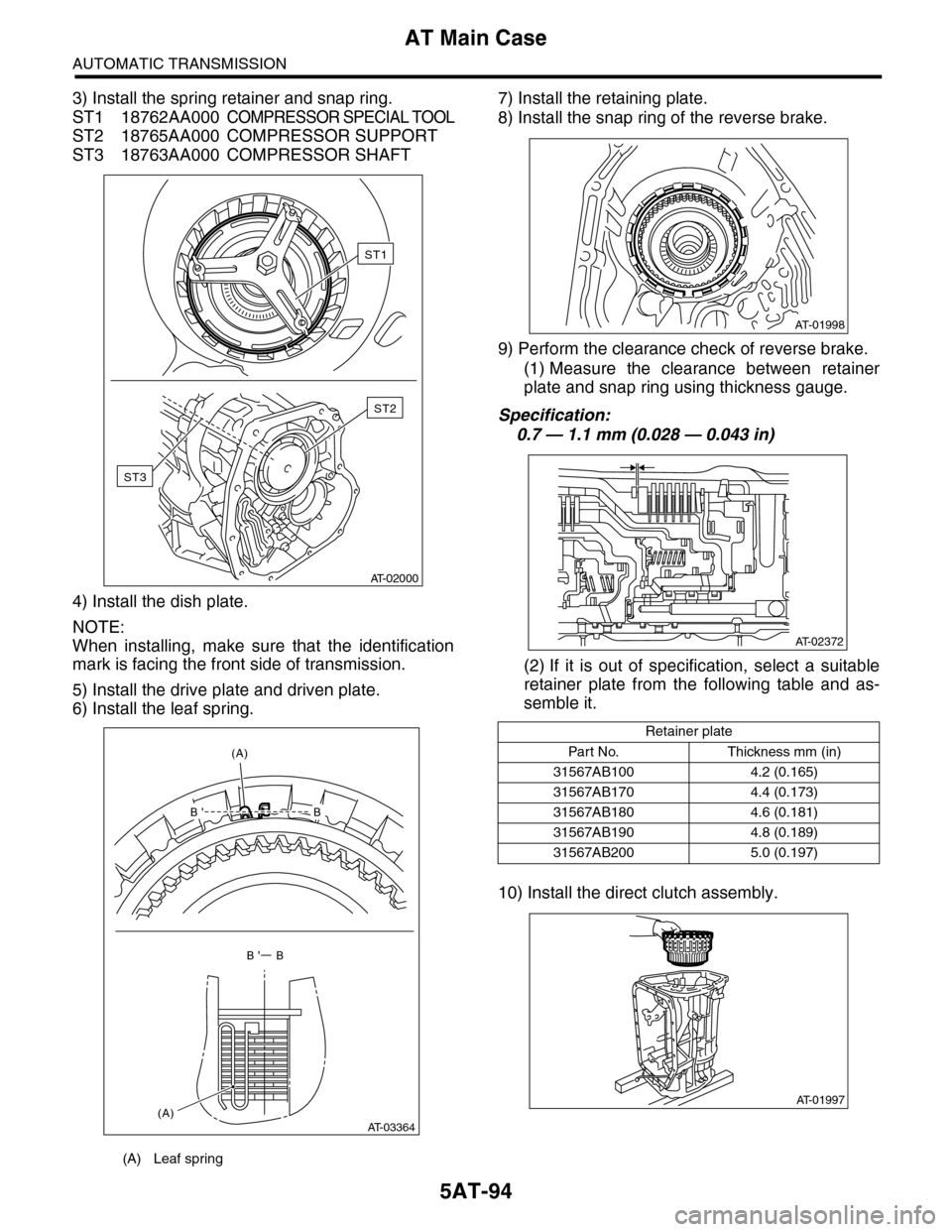
3) Install the spring retainer and snap ring.
ST1 18762AA000COMPRESSOR SPECIAL TOOL
ST2 18765AA000 COMPRESSOR SUPPORT
ST3 18763AA000 COMPRESSOR SHAFT
4) Install the dish plate.
NOTE:
When installing, make sure that the identification
mark is facing the front side of transmission.
5) Install the drive plate and driven plate.
6) Install the leaf spring.
7) Install the retaining plate.
8) Install the snap ring of the reverse brake.
9) Perform the clearance check of reverse brake.
(1) Measure the clearance between retainer
plate and snap ring using thickness gauge.
Specification:
0.7 — 1.1 mm (0.028 — 0.043 in)
(2) If it is out of specification, select a suitable
retainer plate from the following table and as-
semble it.
10) Install the direct clutch assembly.
(A) Leaf spring
AT-02000
ST3
ST2
ST1
B'B
B' B
(A)
(A)AT-03364
Retainer plate
Par t N o. Thickness mm (in)
31567AB100 4.2 (0.165)
31567AB170 4.4 (0.173)
31567AB180 4.6 (0.181)
31567AB190 4.8 (0.189)
31567AB200 5.0 (0.197)
AT-01998
AT-02372
AT-01997
Page 2111 of 2453
5AT-95
AT Main Case
AUTOMATIC TRANSMISSION
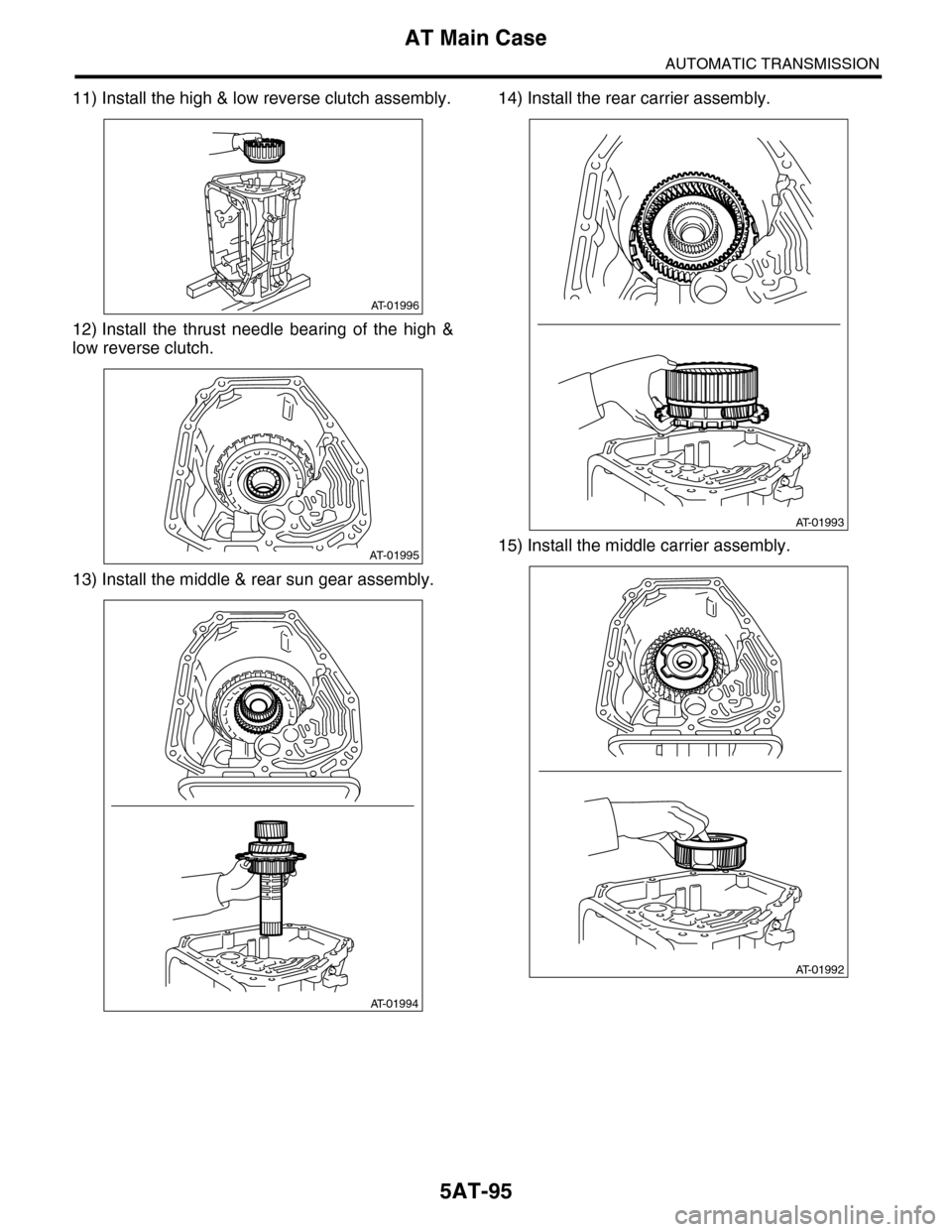
11) Install the high & low reverse clutch assembly.
12) Install the thrust needle bearing of the high &
low reverse clutch.
13) Install the middle & rear sun gear assembly.
14) Install the rear carrier assembly.
15) Install the middle carrier assembly.
AT-01996
AT-01995
AT-01994
AT-01993
AT-01992
Page 2114 of 2453
5AT-98
AT Main Case
AUTOMATIC TRANSMISSION
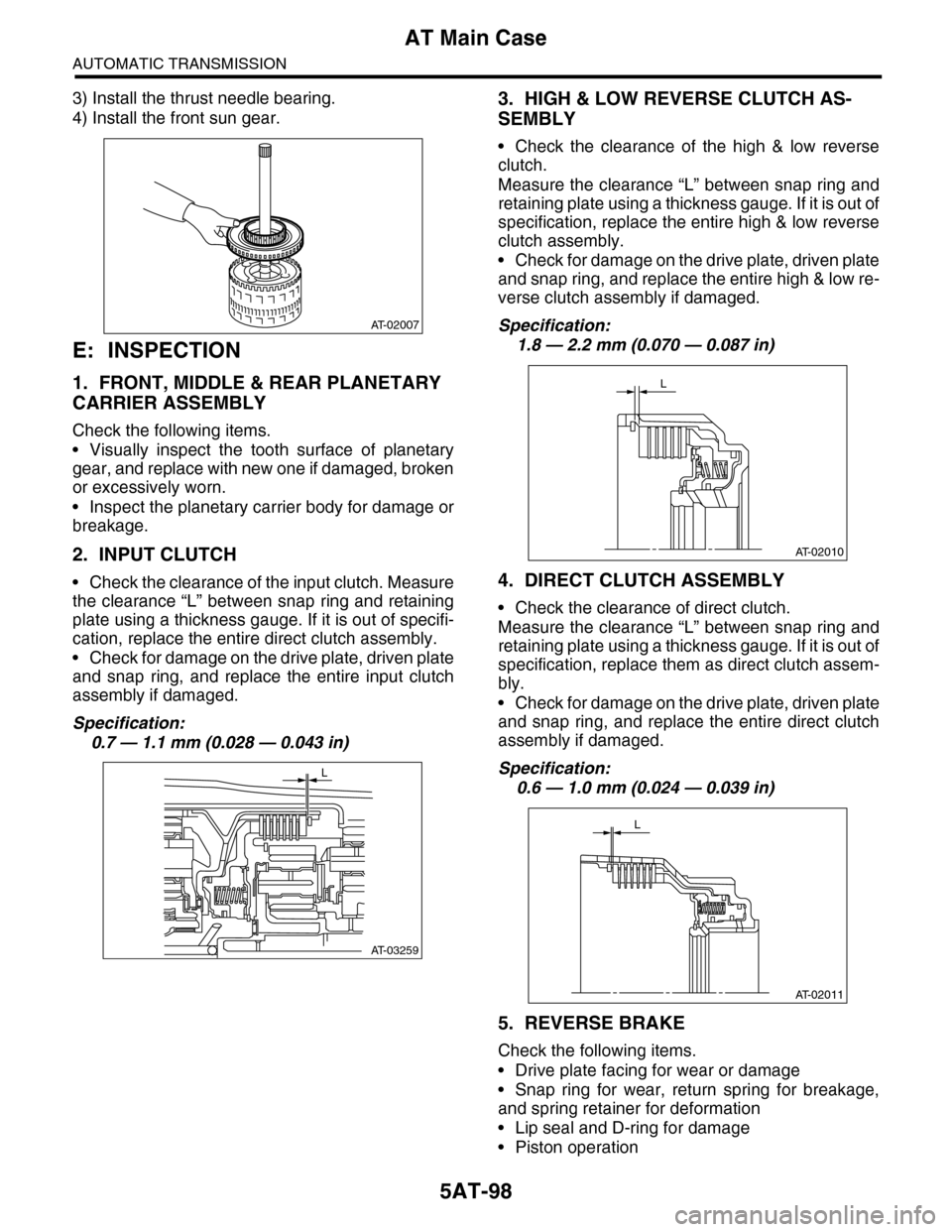
3) Install the thrust needle bearing.
4) Install the front sun gear.
E: INSPECTION
1. FRONT, MIDDLE & REAR PLANETARY
CARRIER ASSEMBLY
Check the following items.
•Visually inspect the tooth surface of planetary
gear, and replace with new one if damaged, broken
or excessively worn.
•Inspect the planetary carrier body for damage or
breakage.
2. INPUT CLUTCH
•Check the clearance of the input clutch. Measure
the clearance “L” between snap ring and retaining
plate using a thickness gauge. If it is out of specifi-
cation, replace the entire direct clutch assembly.
•Check for damage on the drive plate, driven plate
and snap ring, and replace the entire input clutch
assembly if damaged.
Specification:
0.7 — 1.1 mm (0.028 — 0.043 in)
3. HIGH & LOW REVERSE CLUTCH AS-
SEMBLY
•Check the clearance of the high & low reverse
clutch.
Measure the clearance “L” between snap ring and
retaining plate using a thickness gauge. If it is out of
specification, replace the entire high & low reverse
clutch assembly.
•Check for damage on the drive plate, driven plate
and snap ring, and replace the entire high & low re-
verse clutch assembly if damaged.
Specification:
1.8 — 2.2 mm (0.070 — 0.087 in)
4. DIRECT CLUTCH ASSEMBLY
•Check the clearance of direct clutch.
Measure the clearance “L” between snap ring and
retaining plate using a thickness gauge. If it is out of
specification, replace them as direct clutch assem-
bly.
•Check for damage on the drive plate, driven plate
and snap ring, and replace the entire direct clutch
assembly if damaged.
Specification:
0.6 — 1.0 mm (0.024 — 0.039 in)
5. REVERSE BRAKE
Check the following items.
•Drive plate facing for wear or damage
•Snap ring for wear, return spring for breakage,
and spring retainer for deformation
•Lip seal and D-ring for damage
•Piston operation
AT-02007
AT-03259
L
AT-02010
L
AT-02011
L
Page 2127 of 2453
5AT(diag)-10
Electrical Component Location
AUTOMATIC TRANSMISSION (DIAGNOSTICS)
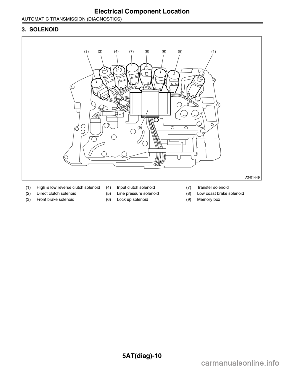
3. SOLENOID
(1) High & low reverse clutch solenoid (4) Input clutch solenoid (7) Transfer solenoid
(2) Direct clutch solenoid (5) Line pressure solenoid (8) Low coast brake solenoid
(3) Front brake solenoid (6) Lock up solenoid (9) Memory box
AT-01449
(8)(6)(5)(1)(7)
(9)
(4)(2)(3)
Page 2133 of 2453
5AT(diag)-16
Subaru Select Monitor
AUTOMATIC TRANSMISSION (DIAGNOSTICS)
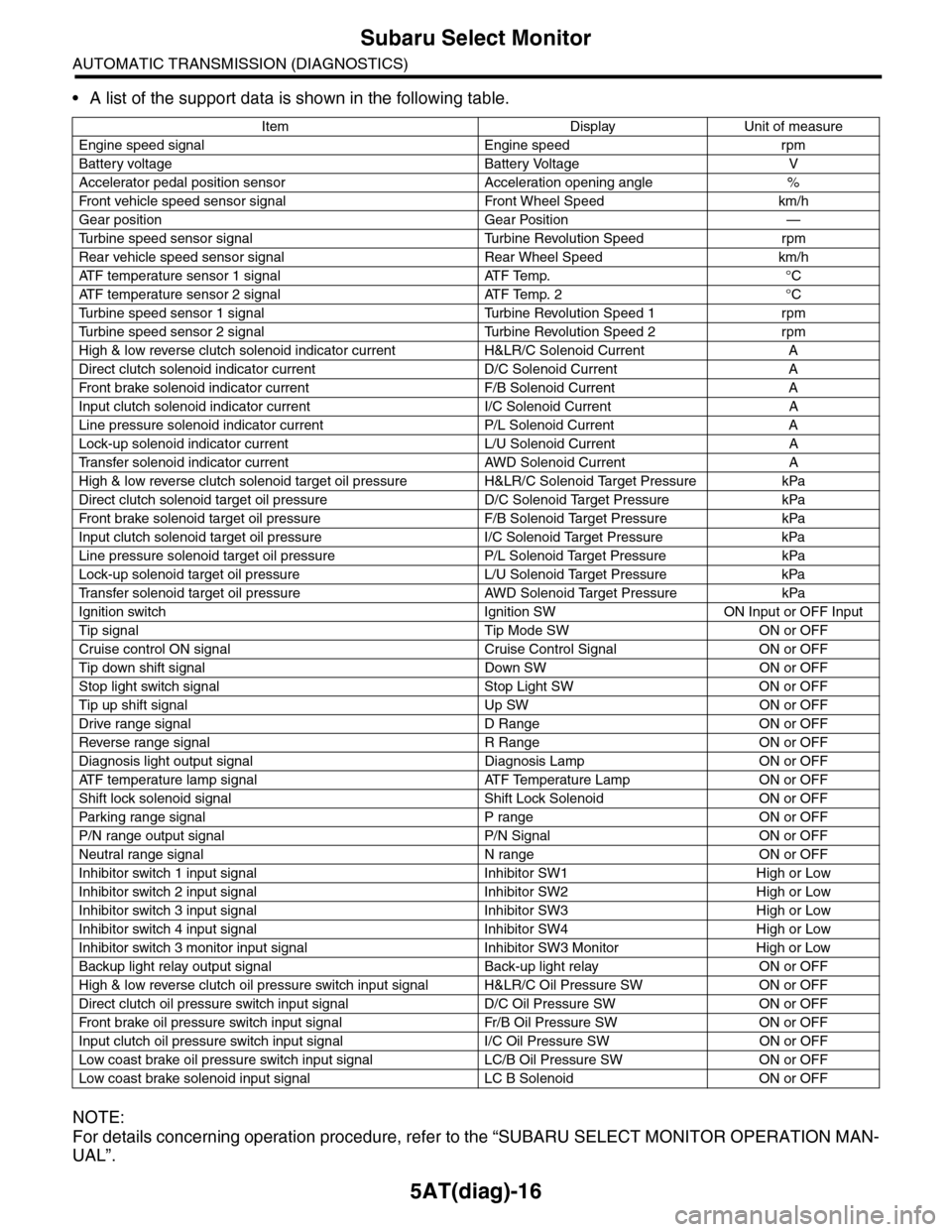
•A list of the support data is shown in the following table.
NOTE:
For details concerning operation procedure, refer to the “SUBARU SELECT MONITOR OPERATION MAN-
UAL”.
Item Display Unit of measure
Engine speed signal Engine speed rpm
Battery voltage Battery Voltage V
Accelerator pedal position sensor Acceleration opening angle %
Fr o nt veh ic l e sp e ed se n so r s ig n al Fr o n t W h ee l S p e ed km/ h
Gear position Gear Position —
Tu r b i n e s p e e d s e n s o r s i g n a l Tu r b i n e R e v o l u t i o n S p e e d r p m
Rear vehicle speed sensor signal Rear Wheel Speed km/h
ATF temperature sensor 1 signal ATF Temp. °C
ATF temperature sensor 2 signal ATF Temp. 2 °C
Tu r b i n e s p e e d s e n s o r 1 s i g n a l Tu r b i n e R e v o l u t i o n S p e e d 1 r p m
Tu r b i n e s p e e d s e n s o r 2 s i g n a l Tu r b i n e R e v o l u t i o n S p e e d 2 r p m
High & low reverse clutch solenoid indicator current H&LR/C Solenoid Current A
Direct clutch solenoid indicator current D/C Solenoid Current A
Fr o nt b rake so l en oi d in di c at o r c u rr e n t F / B S o l en o id Cur r e nt A
Input clutch solenoid indicator current I/C Solenoid Current A
Line pressure solenoid indicator current P/L Solenoid Current A
Lock-up solenoid indicator current L/U Solenoid Current A
Tr a n s f e r s o l e n o i d i n d i c a t o r c u r r e n t A W D S o l e n o i d C u r r e n t A
High & low reverse clutch solenoid target oil pressure H&LR/C Solenoid Target Pressure kPa
Direct clutch solenoid target oil pressure D/C Solenoid Target Pressure kPa
Fr o nt b rake so l en oi d ta r g et o il pr e ss ur e F / B S o l en o id Ta r g et P r es su r e kPa
Input clutch solenoid target oil pressure I/C Solenoid Target Pressure kPa
Line pressure solenoid target oil pressure P/L Solenoid Target Pressure kPa
Lock-up solenoid target oil pressure L/U Solenoid Target Pressure kPa
Tr a n s f e r s o l e n o i d t a r g e t o i l p r e s s u r e A W D S o l e n o i d Ta r g e t P r e s s u r e k P a
Ignition switch Ignition SW ON Input or OFF Input
Tip signal Tip Mode SW ON or OFF
Cruise control ON signal Cruise Control Signal ON or OFF
Tip down shift signal Down SW ON or OFF
Stop light switch signal Stop Light SW ON or OFF
Tip up shift signal Up SW ON or OFF
Drive range signal D Range ON or OFF
Reverse range signal R Range ON or OFF
Diagnosis light output signal Diagnosis Lamp ON or OFF
AT F t e m p e r a t u r e l a m p s i g n a l AT F Te m p e r a t u r e L a m p O N o r O F F
Shift lock solenoid signal Shift Lock Solenoid ON or OFF
Par king range signal P range ON or OFF
P/N range output signal P/N Signal ON or OFF
Neutral range signal N range ON or OFF
Inhibitor switch 1 input signal Inhibitor SW1 High or Low
Inhibitor switch 2 input signal Inhibitor SW2 High or Low
Inhibitor switch 3 input signal Inhibitor SW3 High or Low
Inhibitor switch 4 input signal Inhibitor SW4 High or Low
Inhibitor switch 3 monitor input signal Inhibitor SW3 Monitor High or Low
Backup light relay output signal Back-up light relay ON or OFF
High & low reverse clutch oil pressure switch input signal H&LR/C Oil Pressure SW ON or OFF
Direct clutch oil pressure switch input signal D/C Oil Pressure SW ON or OFF
Fr o nt b rake oi l pr e ss ur e swi tc h i n pu t si gn a l Fr / B Oi l P r e ss ur e S W ON or OF F
Input clutch oil pressure switch input signal I/C Oil Pressure SW ON or OFF
Low coast brake oil pressure switch input signal LC/B Oil Pressure SW ON or OFF
Low coast brake solenoid input signal LC B Solenoid ON or OFF
Page 2145 of 2453
5AT(diag)-28
List of Diagnostic Trouble Code (DTC)
AUTOMATIC TRANSMISSION (DIAGNOSTICS)
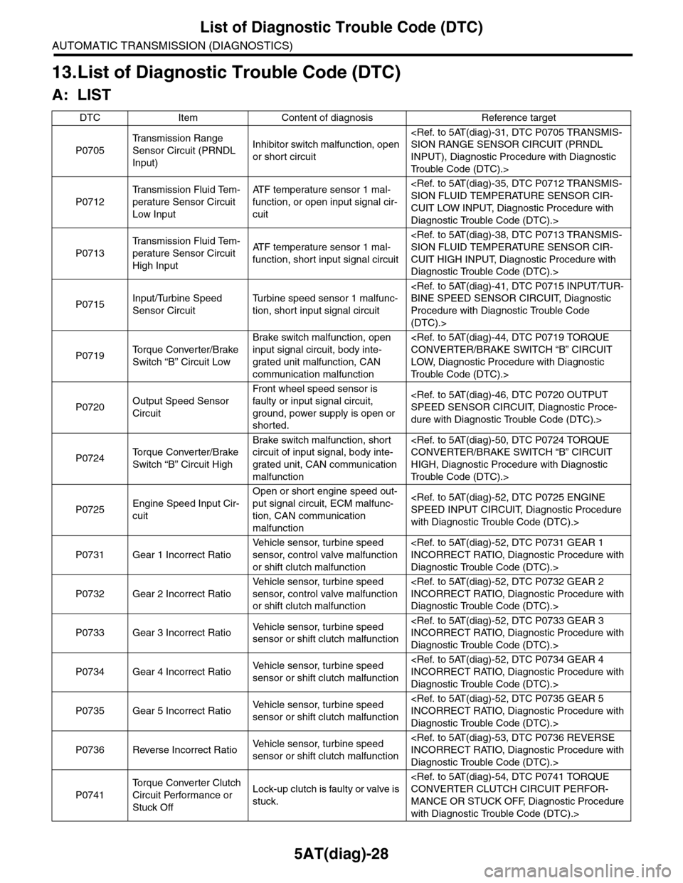
13.List of Diagnostic Trouble Code (DTC)
A: LIST
DTC Item Content of diagnosis Reference target
P0705
Tr a n s m i s s i o n R a n g e
Sensor Circuit (PRNDL
Input)
Inhibitor switch malfunction, open
or short circuit
INPUT), Diagnostic Procedure with Diagnostic
Tr o u b l e C o d e ( D T C ) . >
P0712
Tr a n s m i s s i o n F l u i d Te m -
perature Sensor Circuit
Low Input
AT F t e m p e r a t u r e s e n s o r 1 m a l -
function, or open input signal cir-
cuit
CUIT LOW INPUT, Diagnostic Procedure with
Diagnostic Trouble Code (DTC).>
P0713
Tr a n s m i s s i o n F l u i d Te m -
perature Sensor Circuit
High Input
AT F t e m p e r a t u r e s e n s o r 1 m a l -
function, short input signal circuit
CUIT HIGH INPUT, Diagnostic Procedure with
Diagnostic Trouble Code (DTC).>
P0715Input/Turbine Speed
Sensor Circuit
Tu r b i n e s p e e d s e n s o r 1 m a l f u n c -
tion, short input signal circuit
Procedure with Diagnostic Trouble Code
(DTC).>
P0719To r q u e C o n v e r t e r / B r a k e
Switch “B” Circuit Low
Brake switch malfunction, open
input signal circuit, body inte-
grated unit malfunction, CAN
communication malfunction
LOW, Diagnostic Procedure with Diagnostic
Tr o u b l e C o d e ( D T C ) . >
P0720Output Speed Sensor
Circuit
Front wheel speed sensor is
faulty or input signal circuit,
ground, power supply is open or
shorted.
dure with Diagnostic Trouble Code (DTC).>
P0724To r q u e C o n v e r t e r / B r a k e
Switch “B” Circuit High
Brake switch malfunction, short
circuit of input signal, body inte-
grated unit, CAN communication
malfunction
HIGH, Diagnostic Procedure with Diagnostic
Tr o u b l e C o d e ( D T C ) . >
P0725Engine Speed Input Cir-
cuit
Open or short engine speed out-
put signal circuit, ECM malfunc-
tion, CAN communication
malfunction
with Diagnostic Trouble Code (DTC).>
P0731 Gear 1 Incorrect Ratio
Ve h i c l e s e n s o r, t u r b i n e s p e e d
sensor, control valve malfunction
or shift clutch malfunction
Diagnostic Trouble Code (DTC).>
P0732 Gear 2 Incorrect Ratio
Ve h i c l e s e n s o r, t u r b i n e s p e e d
sensor, control valve malfunction
or shift clutch malfunction
Diagnostic Trouble Code (DTC).>
P0733 Gear 3 Incorrect RatioVe h i c l e s e n s o r, t u r b i n e s p e e d
sensor or shift clutch malfunction
Diagnostic Trouble Code (DTC).>
P0734 Gear 4 Incorrect RatioVe h i c l e s e n s o r, t u r b i n e s p e e d
sensor or shift clutch malfunction
Diagnostic Trouble Code (DTC).>
P0735 Gear 5 Incorrect RatioVe h i c l e s e n s o r, t u r b i n e s p e e d
sensor or shift clutch malfunction
Diagnostic Trouble Code (DTC).>
P0736 Reverse Incorrect RatioVe h i c l e s e n s o r, t u r b i n e s p e e d
sensor or shift clutch malfunction
Diagnostic Trouble Code (DTC).>
P0741
To r q u e C o n v e r t e r C l u t c h
Circuit Performance or
Stuck Off
Lock-up clutch is faulty or valve is
stuck.
MANCE OR STUCK OFF, Diagnostic Procedure
with Diagnostic Trouble Code (DTC).>