Page 1848 of 2453
IN(H6DO)-6
Air Intake Chamber
INTAKE (INDUCTION)
4. Air Intake Chamber
A: REMOVAL
1) Remove the collector cover.
2) Loosen the clamp (A) which connects air intake
chamber to throttle body.
3) Loosen the clamp (B) which connects intake
duct to air intake chamber.
4) Remove the bolt (C) which secures air intake
chamber to the collector cover bracket.
5) Disconnect the blow-by hoses, and then remove
air intake chamber.
B: INSTALLATION
Install in the reverse order of removal.
Tightening torque:
Clamp (A), (B)
3.0 N·m (0.3 kgf-m, 2.2 ft-lb)
Bolt (C)
6.4 N·m (0.65 kgf-m, 4.7 ft-lb)
C: INSPECTION
1) Check for cracks or loose connections.
2) Check that no foreign matter is mixed in air in-
take chamber.
(A)
(C)(C)
(B)
IN-02133
(A)
(C)(C)
(B)
IN-02133
Page 1849 of 2453
IN(H6DO)-7
Air Intake Duct
INTAKE (INDUCTION)
5. Air Intake Duct
A: REMOVAL
1) Remove the clip holding the air intake duct.
2) Remove the air intake duct.
B: INSTALLATION
Install in the reverse order of removal.
C: INSPECTION
1) Check for cracks or loose connections.
2) Check that no foreign matter is mixed in air in-
take duct.
IN-02134
Page 1894 of 2453

ME(H6DO)-28
Valve Clearance
MECHANICAL
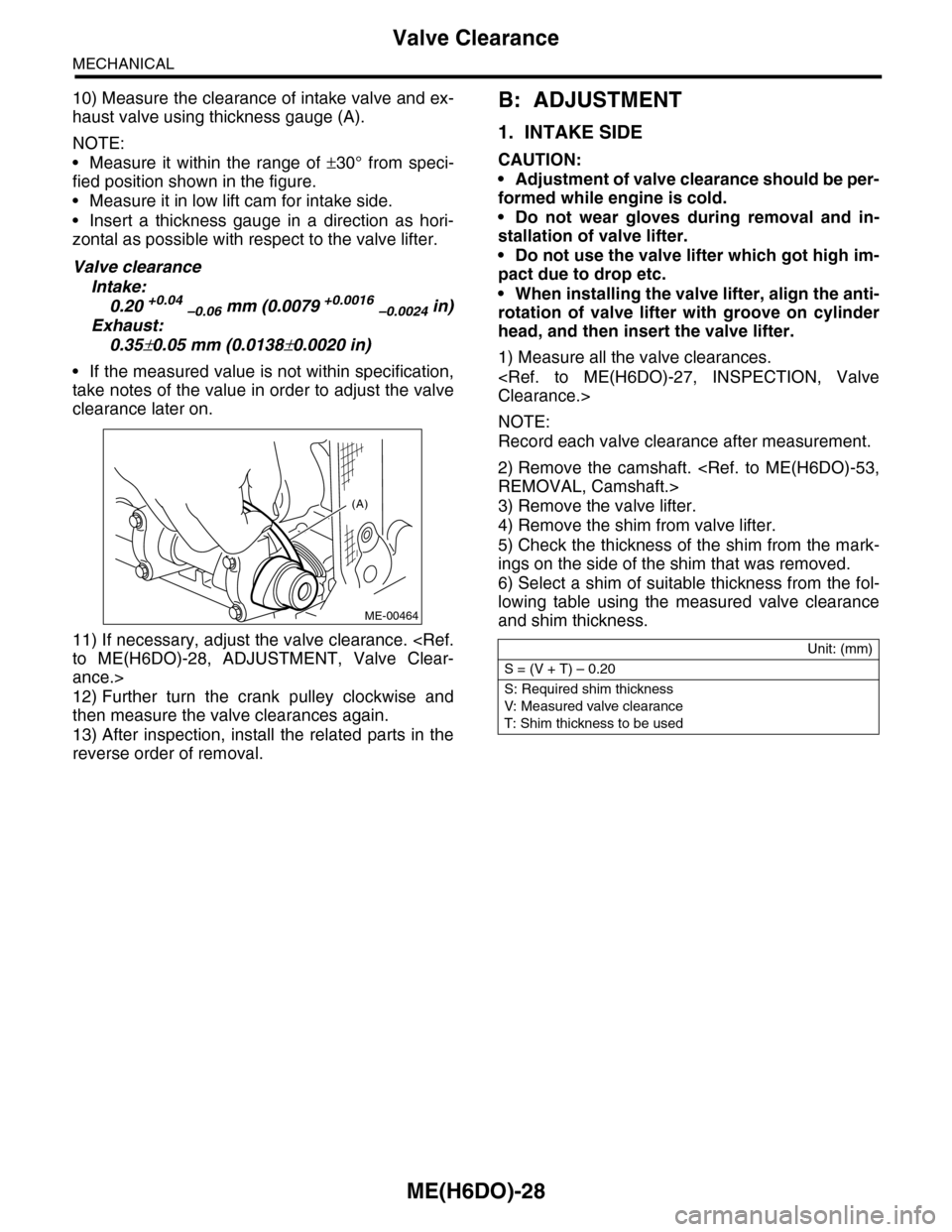
10) Measure the clearance of intake valve and ex-
haust valve using thickness gauge (A).
NOTE:
•Measure it within the range of ±30° from speci-
fied position shown in the figure.
•Measure it in low lift cam for intake side.
•Insert a thickness gauge in a direction as hori-
zontal as possible with respect to the valve lifter.
Valve clearance
Intake:
0.20 +0.04 –0.06 mm (0.0079 +0.0016 –0.0024 in)
Exhaust:
0.35±0.05 mm (0.0138±0.0020 in)
•If the measured value is not within specification,
take notes of the value in order to adjust the valve
clearance later on.
11) If necessary, adjust the valve clearance.
to ME(H6DO)-28, ADJUSTMENT, Valve Clear-
ance.>
12) Further turn the crank pulley clockwise and
then measure the valve clearances again.
13) After inspection, install the related parts in the
reverse order of removal.
B: ADJUSTMENT
1. INTAKE SIDE
CAUTION:
•Adjustment of valve clearance should be per-
formed while engine is cold.
•Do not wear gloves during removal and in-
stallation of valve lifter.
•Do not use the valve lifter which got high im-
pact due to drop etc.
•When installing the valve lifter, align the anti-
rotation of valve lifter with groove on cylinder
head, and then insert the valve lifter.
1) Measure all the valve clearances.
Clearance.>
NOTE:
Record each valve clearance after measurement.
2) Remove the camshaft.
REMOVAL, Camshaft.>
3) Remove the valve lifter.
4) Remove the shim from valve lifter.
5) Check the thickness of the shim from the mark-
ings on the side of the shim that was removed.
6) Select a shim of suitable thickness from the fol-
lowing table using the measured valve clearance
and shim thickness.
(A)
ME-00464
Unit: (mm)
S = (V + T) – 0.20
S: Required shim thickness
V: Measured valve clearance
T: Shim thickness to be used
Page 1897 of 2453
ME(H6DO)-31
V-belt
MECHANICAL
9. V-belt
A: REMOVAL
1) Install the tool to belt tension adjuster assembly
installation bolt.
2) Rotate the tool clockwise and loosen the V-belt
to remove.
3) Remove the V-belt cover.
B: INSTALLATION
Install in the reverse order of removal.
C: INSPECTION
1) Replace the V-belt, if cracks, fraying or wear is
found.
2) Make sure that the V-belt automatic belt tension
indicator (A) is within the range (D).
(1) Power steering oil pump pulley
(2) Belt tension adjuster ASSY
(3) Crank pulley
(4) A/C compressor
(5) Belt idler
(6) Generator
ME-00473
(1)(6)
(4)
(5)(2)
(3)ME-00474
(A) Indicator
(B) Generator
(C) Power steering oil pump pulley
(D) Service limit
(B)
(A)
(D)
(C)
ME-00475
Page 1905 of 2453
ME(H6DO)-39
Engine Mounting
MECHANICAL
11.Engine Mounting
A: REMOVAL
1) Remove the engine unit.
32, REMOVAL, Engine Assembly.>
2) Remove the engine mounting from engine as-
sembly.
B: INSTALLATION
Install in the reverse order of removal.
Tightening torque:
Engine mounting:
35 N·m (3.6 kgf-m, 25.8 ft-lb)
C: INSPECTION
Make sure that there are no cracks or other damag-
es.
Page 1923 of 2453

ME(H6DO)-57
Cylinder Head
MECHANICAL
20.Cylinder Head
A: REMOVAL
1) Remove the crank pulley.
41, REMOVAL, Crank Pulley.>
2) Remove the front chain cover.
ME(H6DO)-42, REMOVAL, Front Chain Cover.>
3) Remove the timing chain assembly.
Assembly.>
4) Remove the cam sprocket.
49, REMOVAL, Cam Sprocket.>
5) Remove the crank sprocket.
et.>
6) Remove the rear chain cover.
Cover.>
7) Remove the camshaft.
REMOVAL, Camshaft.>
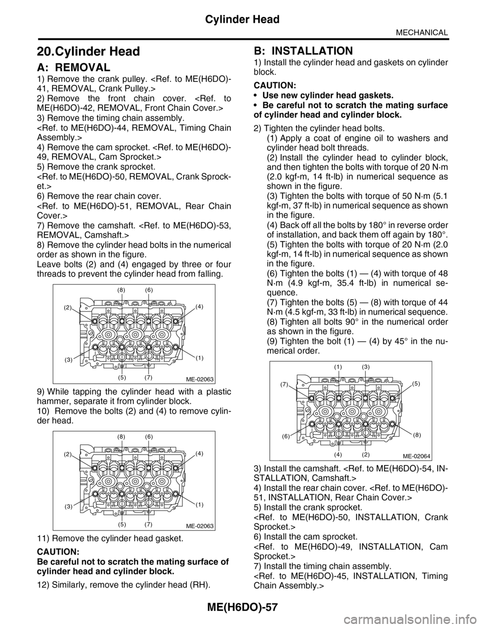
8) Remove the cylinder head bolts in the numerical
order as shown in the figure.
Leave bolts (2) and (4) engaged by three or four
threads to prevent the cylinder head from falling.
9) While tapping the cylinder head with a plastic
hammer, separate it from cylinder block.
10) Remove the bolts (2) and (4) to remove cylin-
der head.
11) Remove the cylinder head gasket.
CAUTION:
Be careful not to scratch the mating surface of
cylinder head and cylinder block.
12) Similarly, remove the cylinder head (RH).
B: INSTALLATION
1) Install the cylinder head and gaskets on cylinder
block.
CAUTION:
•Use new cylinder head gaskets.
•Be careful not to scratch the mating surface
of cylinder head and cylinder block.
2) Tighten the cylinder head bolts.
(1) Apply a coat of engine oil to washers and
cylinder head bolt threads.
(2) Install the cylinder head to cylinder block,
and then tighten the bolts with torque of 20 N·m
(2.0 kgf-m, 14 ft-lb) in numerical sequence as
shown in the figure.
(3) Tighten the bolts with torque of 50 N·m (5.1
kgf-m, 37 ft-lb) in numerical sequence as shown
in the figure.
(4) Back off all the bolts by 180° in reverse order
of installation, and back them off again by 180°.
(5) Tighten the bolts with torque of 20 N·m (2.0
kgf-m, 14 ft-lb) in numerical sequence as shown
in the figure.
(6) Tighten the bolts (1) — (4) with torque of 48
N·m (4.9 kgf-m, 35.4 ft-lb) in numerical se-
quence.
(7) Tighten the bolts (5) — (8) with torque of 44
N·m (4.5 kgf-m, 33 ft-lb) in numerical sequence.
(8) Tighten all bolts 90° in the numerical order
as shown in the figure.
(9) Tighten the bolt (1) — (4) by 45° in the nu-
merical order.
3) Install the camshaft.
STALLATION, Camshaft.>
4) Install the rear chain cover.
51, INSTALLATION, Rear Chain Cover.>
5) Install the crank sprocket.
Sprocket.>
6) Install the cam sprocket.
Sprocket.>
7) Install the timing chain assembly.
Chain Assembly.>
(2)
(8) (6)
(5) (7)
(4)
(1)(3)
ME-02063
(2)
(8) (6)
(5) (7)
(4)
(1)(3)
ME-02063
(7)
(1) (3)
(4) (2)
(5)
(8)(6)
ME-02064
Page 1943 of 2453
ME(H6DO)-77
Oil Flow Control Solenoid Valve
MECHANICAL
22.Oil Flow Control Solenoid
Valve
A: REMOVAL
Oil flow control solenoid valve is a unit with cam-
shaft cap.
Refer to "Camshaft" for removal.
B: INSTALLATION
Install in the reverse order of removal.
Page 1958 of 2453
SP(H6DO)-3
Accelerator Pedal
SPEED CONTROL SYSTEMS
2. Accelerator Pedal
A: REMOVAL
1) Disconnect the ground cable from battery.
2) Disconnect the connector.
3) Remove the nut securing accelerator pedal as-
sembly.
B: INSTALLATION
Install in the reverse order of removal.
Tightening torque:
7.5 N·m (0.76 kgf-m, 5.5 ft-lb)
C: DISASSEMBLY
NOTE:
The accelerator pedal cannot be disassembled.
SP-02035