Page 1964 of 2453

SC(H6DO)-6
Starter
STARTING/CHARGING SYSTEMS
2. Starter
A: REMOVAL
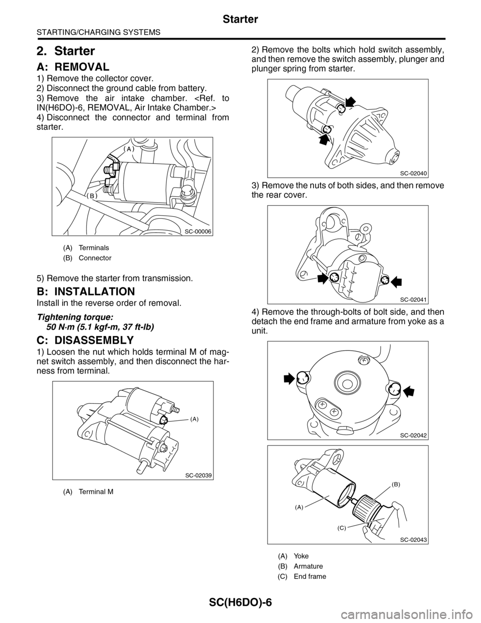
1) Remove the collector cover.
2) Disconnect the ground cable from battery.
3) Remove the air intake chamber.
IN(H6DO)-6, REMOVAL, Air Intake Chamber.>
4) Disconnect the connector and terminal from
starter.
5) Remove the starter from transmission.
B: INSTALLATION
Install in the reverse order of removal.
Tightening torque:
50 N·m (5.1 kgf-m, 37 ft-lb)
C: DISASSEMBLY
1) Loosen the nut which holds terminal M of mag-
net switch assembly, and then disconnect the har-
ness from terminal.
2) Remove the bolts which hold switch assembly,
and then remove the switch assembly, plunger and
plunger spring from starter.
3) Remove the nuts of both sides, and then remove
the rear cover.
4) Remove the through-bolts of bolt side, and then
detach the end frame and armature from yoke as a
unit.
(A) Terminals
(B) Connector
(A) Terminal M
SC-00006
(A)
SC-02039
(A) Yoke
(B) Armature
(C) End frame
SC-02040
SC-02041
SC-02042
SC-02043
(A)
(C)
(B)
Page 1977 of 2453
SC(H6DO)-19
Generator
STARTING/CHARGING SYSTEMS
3. Generator
A: REMOVAL
1) Remove the collector cover.
2) Disconnect the ground cable from battery.
3) Disconnect the connector and terminal from
generator.
4) Remove the V-belts.
REMOVAL, V-belt.>
5) Remove the bolts which install the generator
onto bracket.
B: INSTALLATION
Install in the reverse order of removal.
Tightening torque:
25 N·m (2.5 kgf-m, 18.1 ft-lb)
CAUTION:
Check and adjust the V-belt tension.
C: DISASSEMBLY
1) Remove the four through-bolts.
2) Heat the portion (A) of rear cover to 50°C
(122°F) with a heater drier.
3) Then insert the tip of a flat tip screwdriver into the
gap between stator core and front cover. Pry them
apart to disassemble.
4) Hold the rotor with a vise and remove pulley nut.
SC-02003
SC-02098
SC-02098
(A) Screwdriver
SC-00078
SC-00079
(A)
SC-00080
(A)
(A)
SC-00035
Page 1980 of 2453

SC(H6DO)-22
Generator
STARTING/CHARGING SYSTEMS
D: ASSEMBLY
Assemble in the reverse order of disassembly.
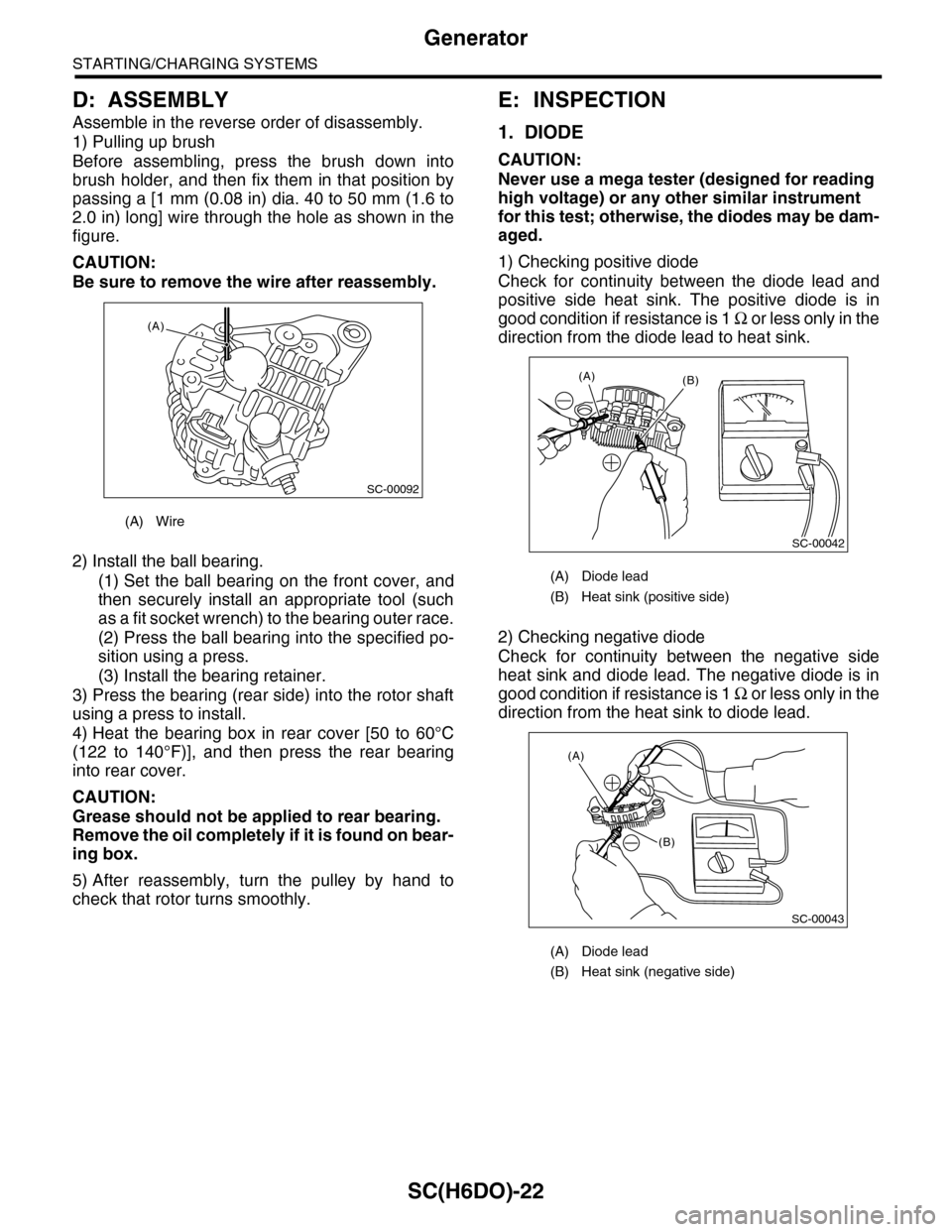
1) Pulling up brush
Before assembling, press the brush down into
brush holder, and then fix them in that position by
passing a [1 mm (0.08 in) dia. 40 to 50 mm (1.6 to
2.0 in) long] wire through the hole as shown in the
figure.
CAUTION:
Be sure to remove the wire after reassembly.
2) Install the ball bearing.
(1) Set the ball bearing on the front cover, and
then securely install an appropriate tool (such
as a fit socket wrench) to the bearing outer race.
(2) Press the ball bearing into the specified po-
sition using a press.
(3) Install the bearing retainer.
3) Press the bearing (rear side) into the rotor shaft
using a press to install.
4) Heat the bearing box in rear cover [50 to 60°C
(122 to 140°F)], and then press the rear bearing
into rear cover.
CAUTION:
Grease should not be applied to rear bearing.
Remove the oil completely if it is found on bear-
ing box.
5) After reassembly, turn the pulley by hand to
check that rotor turns smoothly.
E: INSPECTION
1. DIODE
CAUTION:
Never use a mega tester (designed for reading
high voltage) or any other similar instrument
for this test; otherwise, the diodes may be dam-
aged.
1) Checking positive diode
Check for continuity between the diode lead and
positive side heat sink. The positive diode is in
good condition if resistance is 1 Ω o r l e s s o n l y i n t h e
direction from the diode lead to heat sink.
2) Checking negative diode
Check for continuity between the negative side
heat sink and diode lead. The negative diode is in
good condition if resistance is 1 Ω o r l e s s o n l y i n t h e
direction from the heat sink to diode lead.
(A) Wire
SC-00092
(A)
(A) Diode lead
(B) Heat sink (positive side)
(A) Diode lead
(B) Heat sink (negative side)
SC-00042
(B)(A)
(A)
(B)
SC-00043
Page 1983 of 2453

SC(H6DO)-25
Battery
STARTING/CHARGING SYSTEMS
4. Battery
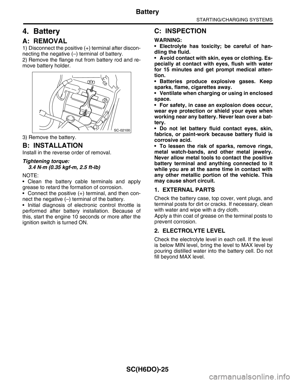
A: REMOVAL
1) Disconnect the positive (+) terminal after discon-
necting the negative (–) terminal of battery.
2) Remove the flange nut from battery rod and re-
move battery holder.
3) Remove the battery.
B: INSTALLATION
Install in the reverse order of removal.
Tightening torque:
3.4 N·m (0.35 kgf-m, 2.5 ft-lb)
NOTE:
•Clean the battery cable terminals and apply
grease to retard the formation of corrosion.
•Connect the positive (+) terminal, and then con-
nect the negative (–) terminal of the battery.
•Initial diagnosis of electronic control throttle is
performed after battery installation. Because of
this, start the engine 10 seconds or more after the
ignition switch is turned ON.
C: INSPECTION
WARNING:
•Electrolyte has toxicity; be careful of han-
dling the fluid.
•Avoid contact with skin, eyes or clothing. Es-
pecially at contact with eyes, flush with water
for 15 minutes and get prompt medical atten-
tion.
•Batteries produce explosive gases. Keep
sparks, flame, cigarettes away.
•Ventilate when charging or using in enclosed
space.
•For safety, in case an explosion does occur,
wear eye protection or shield your eyes when
working near any battery. Never lean over a bat-
tery.
•Do not let battery fluid contact eyes, skin,
fabrics, or paint-work because battery fluid is
corrosive acid.
•To lessen the risk of sparks, remove rings,
metal watch-bands, and other metal jewelry.
Never allow metal tools to contact the positive
battery terminal and anything connected to it
while you are at the same time in contact with
any other metallic portion of the vehicle. This
may cause short circuit.
1. EXTERNAL PARTS
Check the battery case, top cover, vent plugs, and
terminal posts for dirt or cracks. If necessary, clean
with water and wipe with a dry cloth.
Apply a thin coat of grease on the terminal posts to
prevent corrosion.
2. ELECTROLYTE LEVEL
Check the electrolyte level in each cell. If the level
is below MIN level, bring the level to MAX level by
pouring distilled water into the battery cell. Do not
fill beyond MAX level.
SC-02100
Page 1993 of 2453
PM-10
V-belt
PERIODIC MAINTENANCE SERVICES
6. V-belt
A: INSPECTION
1) Replace the belts if cracks, fraying or wear are
found.
2) Make sure that the V-belt automatic belt tension
indicator (A) is within the range of its use limit (D).
B: REPLACEMENT
1) Remove the cover.
2) Fit the tool to the belt tensioner mounting bolt.
3) Turn the tool in the direction of the arrow, and
loosen the V-belt to remove it.
4) Install in the reverse order of removal.
(A) Indicator
(B) Generator
(C) Power steering oil pump
(D) Service limit
(B)
(A)
(D)
(C)
ME-00475
(1) Power steering oil pump
(2) Belt tension adjuster
(3) Crank pulley
(4) A/C compressor
(5) Belt idler
(6) Generator
PM-00301
(1)(6)
(4)
(5)(2)
(3)ME-00474
Page 1995 of 2453
PM-12
Air Cleaner Element
PERIODIC MAINTENANCE SERVICES
8. Air Cleaner Element
A: REPLACEMENT
1) Disconnect the ground cable from battery.
2) Remove the clips (B) on air cleaner case.
3) While pushing the duct toward the back end of
the vehicle, remove the air cleaner element.
4) Install in the reverse order of removal.
NOTE:
Fasten with a clip after inserting the lower tab of
case.
PM-00284
(A)
PM-00285
Page 2018 of 2453

5AT-2
General Description
AUTOMATIC TRANSMISSION
1. General Description
A: SPECIFICATION
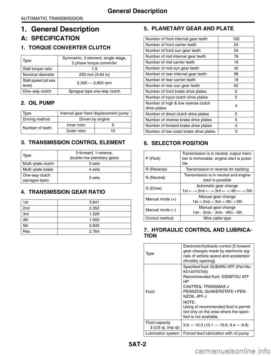
1. TORQUE CONVERTER CLUTCH
2. OIL PUMP
3. TRANSMISSION CONTROL ELEMENT
4. TRANSMISSION GEAR RATIO
5. PLANETARY GEAR AND PLATE
6. SELECTOR POSITION
7. HYDRAULIC CONTROL AND LUBRICA-
TION
Ty p eSymmetric, 3 element, single stage,
2 phase torque converter
Stall torque ratio 1.9
Nominal diameter 250 mm (9.84 in)
Stall speed (at sea
level)2,300 — 2,800 rpm
One–way clutch Sprague type one-way clutch
Ty p e I n t e r n a l g e a r f i x e d d i s p l a c e m e n t p u m p
Driving method Driven by engine
Number of teethInner rotor 9
Outer rotor 10
Ty p e5-forward, 1-reverse,
double-row planetary gears
Multi–plate clutch 3 sets
Multi–plate brake 4 sets
One-way clutch
(sprague type)3 sets
1st 3.841
2nd 2.352
3rd 1.529
4th 1.000
5th 0.839
Rev. 2.764
Number of front internal gear teeth 102
Number of front carrier teeth 24
Number of front sun gear teeth 54
Number of mid internal gear teeth 78
Number of mid carrier teeth 18
Number of mid sun gear teeth 42
Number of rear internal gear teeth 98
Number of rear carrier teeth 18
Number of rear sun gear teeth 62
Number of front brake drive plates 2
Number of input clutch drive plates 5
Number of high & low reverse clutch
drive plates4
Number of direct clutch drive plates 5
Number of reverse brake drive plates 5
Number of forward brake drive plates 4
Number of low coast brake drive plates 3
P (Park)
Tr a n s m i s s i o n i s i n n e u t r a l , o u t p u t m e m -
ber is immovable, engine start is possi-
ble
R (Reverse) Transmission in reverse for backing
N (Neutral)Tr a n s m i s s i o n i s i n n e u t r a l a n d e n g i n e
start is possible
D (Drive)Automatic gear change
1st ←→ 2nd ←→ 3rd ←→ 4th ←→ 5th
Manual mode (+)Manual gear change
1st→ 2nd→ 3rd→ 4th→ 5th
Manual mode (–)Manual gear change
1st← 2nd← 3rd← 4th← 5th
Control method Wire cable type
Ty p e
Electronic/hydraulic control [5 forward
gear changes made by electronic sig-
nals of vehicle speed and accelerator
(throttle) opening]
Fluid
Specified fluid: SUBARU ATF (Part No.
K0140Y0700)
Recommended fluid: IDEMITSU ATF
HP
CASTROL TRANSMAX J
PENNZOIL QUAKERSTATE • PEN-
NZOIL ATF-J
NOTE:
Using of recommended fluid is permit-
ted only on the area where the speci-
fied is not available.
Fluid capacity
2(US qt, Imp qt)9.6 — 10.0 (10.1 — 10.6, 8.4 — 8.8)
Lubrication system Forced feed lubrication with oil pump
Page 2023 of 2453
5AT-7
General Description
AUTOMATIC TRANSMISSION
4. DIRECT CLUTCH AND HIGH & LOW REVERSE CLUTCH
(1) Thrust bearing (2) High & low reverse clutch ASSY (3) Direct clutch ASSY
AT-02018
(3)
(2)
(1)