Page 2024 of 2453
5AT-8
General Description
AUTOMATIC TRANSMISSION
5. REVERSE BRAKE
(1) Snap ring (6) Dish plate (10) Reverse brake piston
(2) Retainer plate (7) Snap ring (11) D-ring (Outer)
(3) Leaf spring (8) Retainer (12) D-ring (Inner)
(4) Drive plate (9) Leaf spring (13) AT main case
(5) Driven plate
AT-03007
(1)
(6)
(5)
(7)
(8)
(9)
(10)
(11)
(12)
(4)
(2)(3)(13)
Page 2046 of 2453
5AT-30
Stall Test
AUTOMATIC TRANSMISSION
5. Stall Test
A: INSPECTION
NOTE:
The stall test is extremely important in diagnosing
the condition of an automatic transmission and en-
gine. It should be conducted to measure the engine
stall speeds in “R” and “2nd of manual mode”.
Purposes of the stall test:
•Operational check of the automatic transmission
clutch
•Operational check of the torque converter clutch
•Engine performance check
1) Check that the throttle valve fully opens.
2) Check that the engine oil level is correct.
3) Check that the coolant level is correct.
4) Check that the ATF level is correct.
5) Check that the differential gear oil level is cor-
rect.
6) Raise the ATF temperature to 70 to 80°C (158 to
176°F) by driving a distance of 5 to 10 km (3 to 6
miles). Confirm the ATF temperature on Subaru
Select Monitor.
RENT DATA, OPERATION, Subaru Select Moni-
tor.>
7) Place the wheel chocks at the front and rear of
all wheels and apply the parking brake.
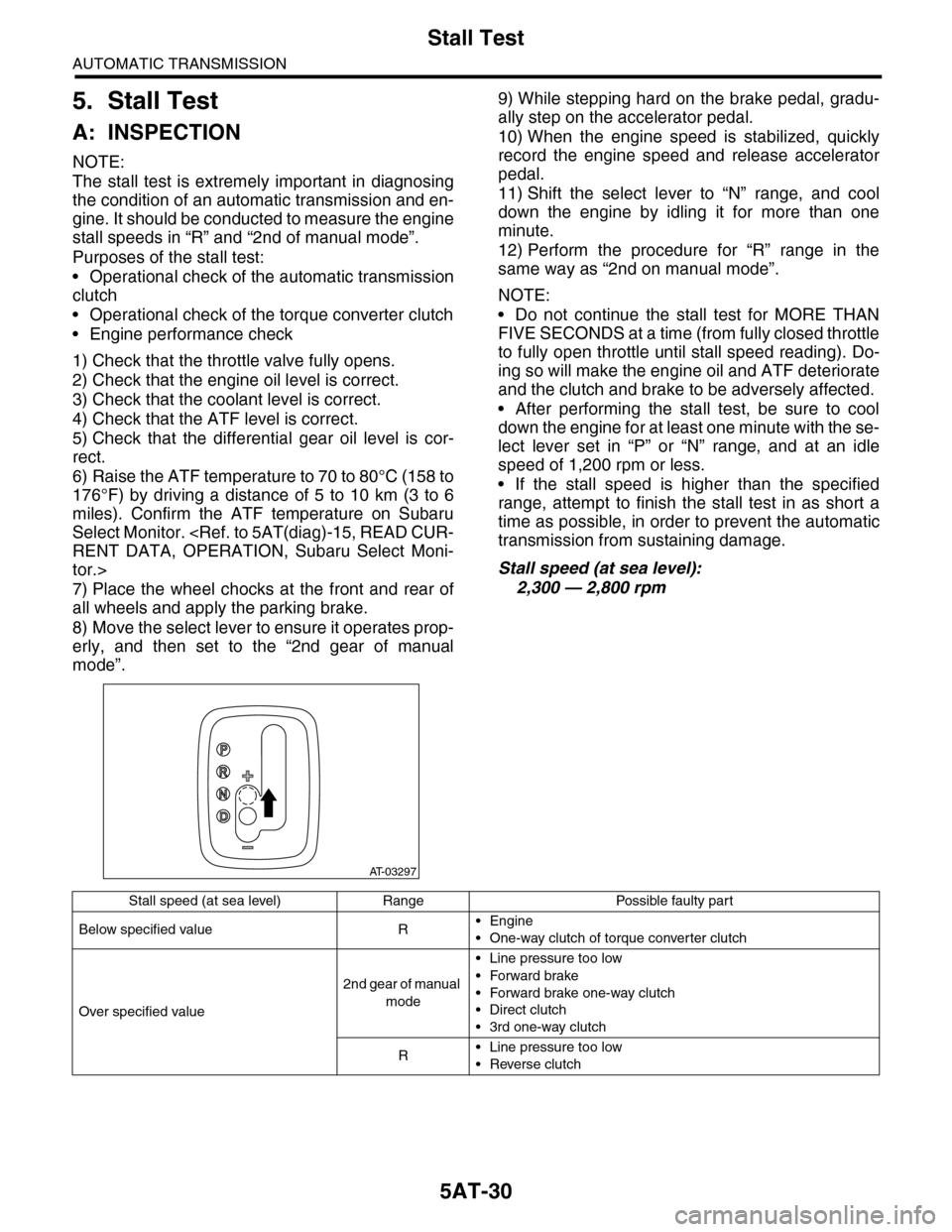
8) Move the select lever to ensure it operates prop-
erly, and then set to the “2nd gear of manual
mode”.
9) While stepping hard on the brake pedal, gradu-
ally step on the accelerator pedal.
10) When the engine speed is stabilized, quickly
record the engine speed and release accelerator
pedal.
11) Shift the select lever to “N” range, and cool
down the engine by idling it for more than one
minute.
12) Perform the procedure for “R” range in the
same way as “2nd on manual mode”.
NOTE:
•Do not continue the stall test for MORE THAN
FIVE SECONDS at a time (from fully closed throttle
to fully open throttle until stall speed reading). Do-
ing so will make the engine oil and ATF deteriorate
and the clutch and brake to be adversely affected.
•After performing the stall test, be sure to cool
down the engine for at least one minute with the se-
lect lever set in “P” or “N” range, and at an idle
speed of 1,200 rpm or less.
•If the stall speed is higher than the specified
range, attempt to finish the stall test in as short a
time as possible, in order to prevent the automatic
transmission from sustaining damage.
Stall speed (at sea level):
2,300 — 2,800 rpm
AT-03297
Stall speed (at sea level) Range Possible faulty part
Below specified value R•Engine
•One-way clutch of torque converter clutch
Over specified value
2nd gear of manual
mode
•Line pressure too low
•Forward brake
•Forward brake one-way clutch
•Direct clutch
•3rd one-way clutch
R•Line pressure too low
•Reverse clutch
Page 2047 of 2453
5AT-31
Time Lag Test
AUTOMATIC TRANSMISSION
6. Time Lag Test
A: INSPECTION
NOTE:
When the select lever is shifted while the engine is
idling, there will be a certain time elapse or lag be-
fore shock is felt. Using this, check the condition of
forward brake, reverse brake, 1st one-way clutch,
forward one-way clutch and 3rd one-way clutch.
•Perform the test at normal operation fluid tem-
perature of 70 — 80°C (158 — 176°F).
•Be sure to allow a one minute interval between
tests.
•Make three measurements and take the average
value.
1) Fully apply the parking brake.
2) Start the engine.
Check the idle speed (A/C OFF).
3) Shift the select lever from “N” to “D” range. Using
a stop watch, measure the time-lag from shifting
the lever until the shock is felt.
Time-lag
Specification: 1.2 sec. or less
If “N” → “D” time-lag is longer than specification:
•Line pressure too low
•Forward brake worn
•One–way clutch not operating properly
4) In the same manner, measure the time lag of “N”
→ “R”.
Time-lag
Specification: 1.5 sec. or less
If “N” → “R” time lag is longer than specification:
•Line pressure too low
•Reverse brake worn
Page 2072 of 2453
5AT-56
Transmission Control Module (TCM)
AUTOMATIC TRANSMISSION
19.Transmission Control Mod-
ule (TCM)
A: REMOVAL
1) Disconnect the ground cable from battery.
2) Remove the lower cover and then disconnect
the connector.
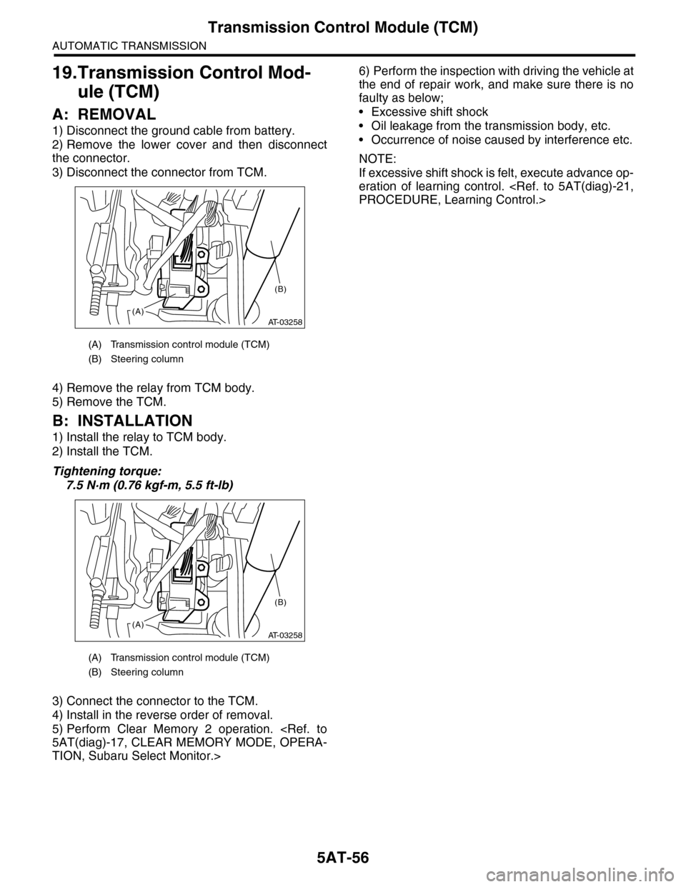
3) Disconnect the connector from TCM.
4) Remove the relay from TCM body.
5) Remove the TCM.
B: INSTALLATION
1) Install the relay to TCM body.
2) Install the TCM.
Tightening torque:
7.5 N·m (0.76 kgf-m, 5.5 ft-lb)
3) Connect the connector to the TCM.
4) Install in the reverse order of removal.
5) Perform Clear Memory 2 operation.
5AT(diag)-17, CLEAR MEMORY MODE, OPERA-
TION, Subaru Select Monitor.>
6) Perform the inspection with driving the vehicle at
the end of repair work, and make sure there is no
faulty as below;
•Excessive shift shock
•Oil leakage from the transmission body, etc.
•Occurrence of noise caused by interference etc.
NOTE:
If excessive shift shock is felt, execute advance op-
eration of learning control.
PROCEDURE, Learning Control.>
(A) Transmission control module (TCM)
(B) Steering column
(A) Transmission control module (TCM)
(B) Steering column
AT-03258(A)
(B)
AT-03258(A)
(B)
Page 2083 of 2453
5AT-67
Rear Drive Shaft
AUTOMATIC TRANSMISSION
26.Rear Drive Shaft
A: REMOVAL
1) Remove the transmission assembly from vehicle
body.
Transmission Assembly.>
2) Remove the rear vehicle speed sensor, and then
remove the extension case.
MOVAL, Extension Case.>
3) Pull out the rear driveshaft from center differen-
tial assembly.
4) Remove the drive plate and driven plate.
B: INSTALLATION
1) Select the shim.
MENT, Transfer Clutch.>
2) Install drive plate and driven plate.
3) Insert the rear driveshaft into the center differen-
tial assembly.
4) Combine the extension case, and then install the
rear vehicle speed sensor.
STALLATION, Extension Case.>
5) Install the transmission assembly to the vehicle.
Transmission Assembly.>
C: DISASSEMBLY
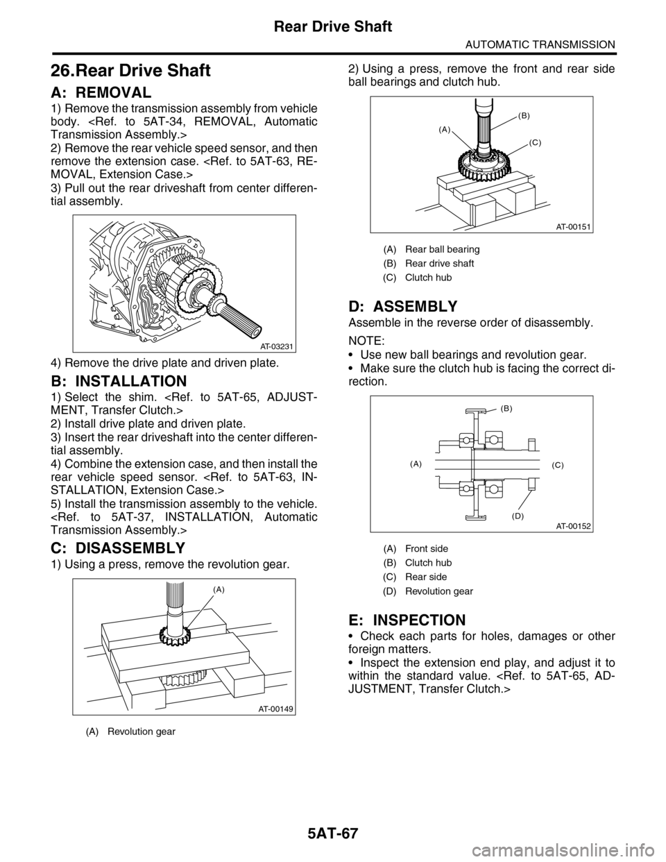
1) Using a press, remove the revolution gear.
2) Using a press, remove the front and rear side
ball bearings and clutch hub.
D: ASSEMBLY
Assemble in the reverse order of disassembly.
NOTE:
•Use new ball bearings and revolution gear.
•Make sure the clutch hub is facing the correct di-
rection.
E: INSPECTION
•Check each parts for holes, damages or other
foreign matters.
•Inspect the extension end play, and adjust it to
within the standard value.
JUSTMENT, Transfer Clutch.>
(A) Revolution gear
AT-03231
AT-00149
(A)
(A) Rear ball bearing
(B) Rear drive shaft
(C) Clutch hub
(A) Front side
(B) Clutch hub
(C) Rear side
(D) Revolution gear
AT-00151
(A)
(B)
(C)
AT-00152
(A)
(B)
(C)
(D)
Page 2084 of 2453
5AT-68
Reduction Driven Gear
AUTOMATIC TRANSMISSION
27.Reduction Driven Gear
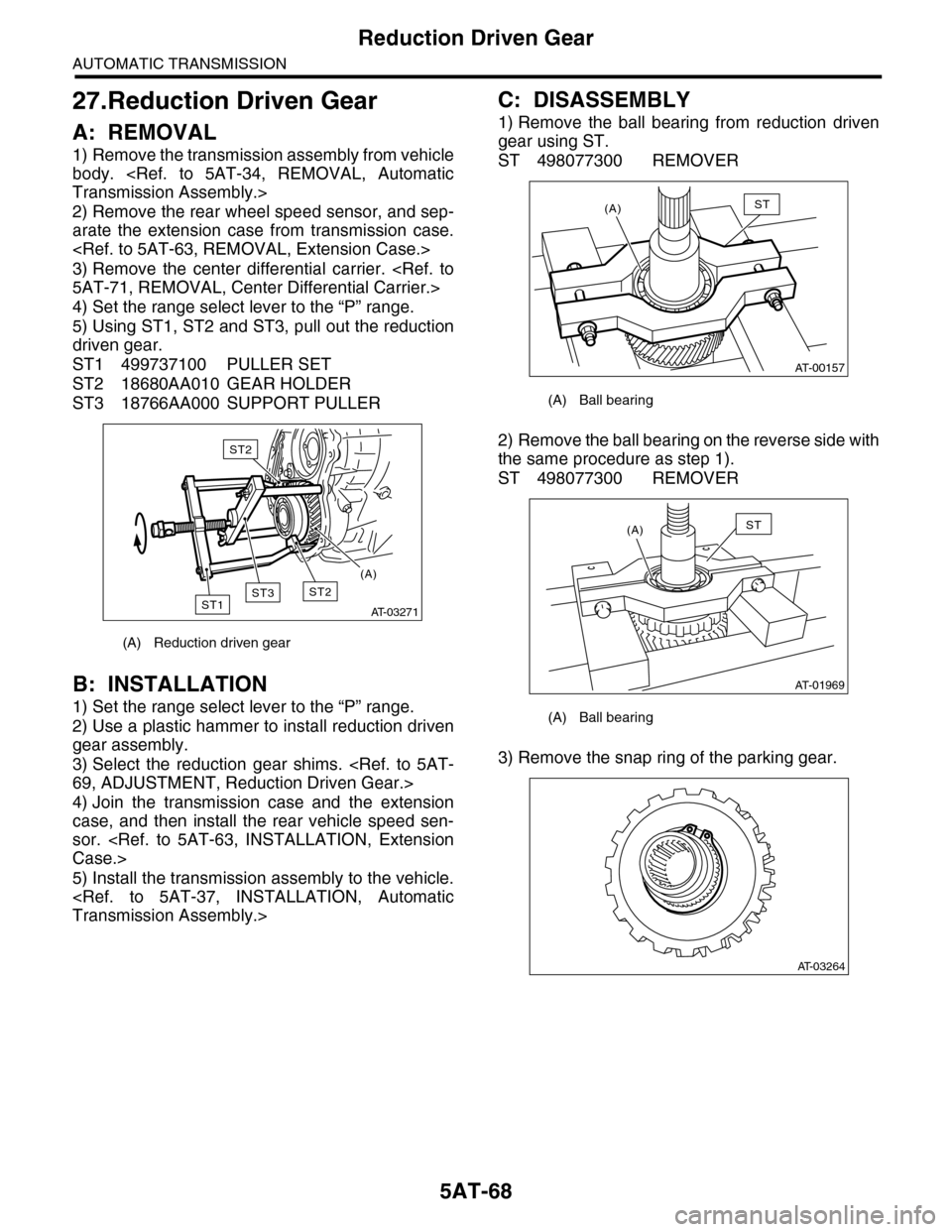
A: REMOVAL
1) Remove the transmission assembly from vehicle
body.
Transmission Assembly.>
2) Remove the rear wheel speed sensor, and sep-
arate the extension case from transmission case.
3) Remove the center differential carrier.
5AT-71, REMOVAL, Center Differential Carrier.>
4) Set the range select lever to the “P” range.
5) Using ST1, ST2 and ST3, pull out the reduction
driven gear.
ST1 499737100 PULLER SET
ST2 18680AA010 GEAR HOLDER
ST3 18766AA000 SUPPORT PULLER
B: INSTALLATION
1) Set the range select lever to the “P” range.
2) Use a plastic hammer to install reduction driven
gear assembly.
3) Select the reduction gear shims.
69, ADJUSTMENT, Reduction Driven Gear.>
4) Join the transmission case and the extension
case, and then install the rear vehicle speed sen-
sor.
Case.>
5) Install the transmission assembly to the vehicle.
Transmission Assembly.>
C: DISASSEMBLY
1) Remove the ball bearing from reduction driven
gear using ST.
ST 498077300 REMOVER
2) Remove the ball bearing on the reverse side with
the same procedure as step 1).
ST 498077300 REMOVER
3) Remove the snap ring of the parking gear.
(A) Reduction driven gear
AT-03271
ST2ST1
ST2
ST3
(A)
(A) Ball bearing
(A) Ball bearing
AT-00157
(A)ST
AT-01969
(A)ST
AT-03264
Page 2085 of 2453
5AT-69
Reduction Driven Gear
AUTOMATIC TRANSMISSION
4) Using the ST, remove the parking gear.
ST 18767AA000 REMOVER
D: ASSEMBLY
1) Using the ST, install the parking gear.
ST 499755602 PRESS
2) Install the snap ring.
3) Install the new ball bearing to reduction driven
gear using press.
ST 18654AA000 INSTALLER
4) Install the ball bearing on the reverse side with
the same procedure as step 3).
ST 18654AA000 INSTALLER
E: INSPECTION
Make sure the ball bearing and gear is not de-
formed or damaged.
F: ADJUSTMENT
1) Using the ST, measure the height “A” from the
AT main case mating surface to ball bearing outer
ring contact surface.
ST 499575400 GAUGE
2) Using the ST, measure the depth “B”, which is
from mating surface of extension case to ball bear-
ing outer ring contact surface.
ST 499575400 GAUGE
(A) Ball bearing 1
AT-03265
ST
ST
AT-03264
AT-03267
ST
AT-03268
ST
AT-03269
ST
A
AT-03270
ST
B
Page 2104 of 2453
5AT-88
Front Differential Assembly
AUTOMATIC TRANSMISSION
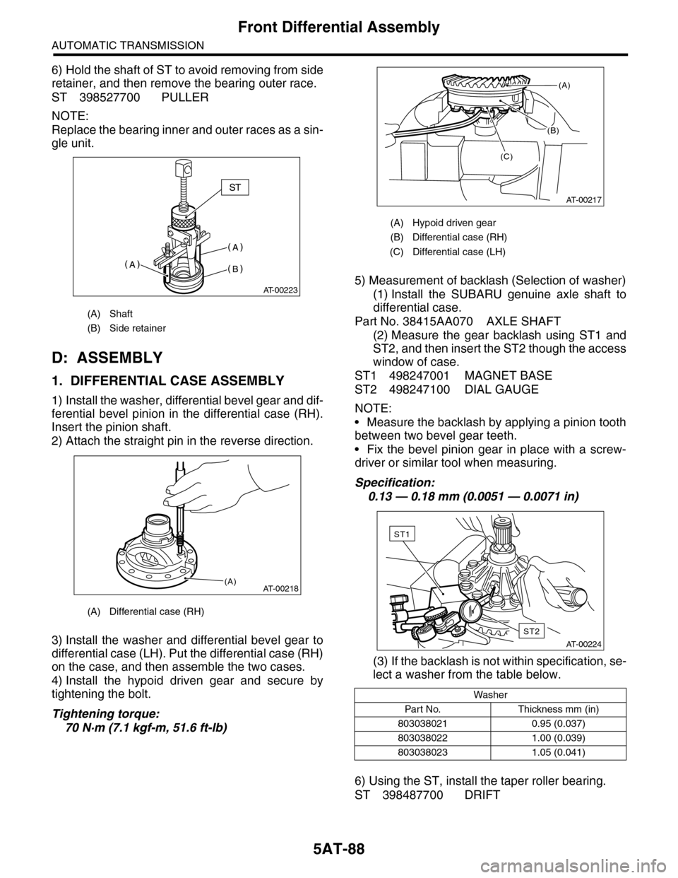
6) Hold the shaft of ST to avoid removing from side
retainer, and then remove the bearing outer race.
ST 398527700 PULLER
NOTE:
Replace the bearing inner and outer races as a sin-
gle unit.
D: ASSEMBLY
1. DIFFERENTIAL CASE ASSEMBLY
1) Install the washer, differential bevel gear and dif-
ferential bevel pinion in the differential case (RH).
Insert the pinion shaft.
2) Attach the straight pin in the reverse direction.
3) Install the washer and differential bevel gear to
differential case (LH). Put the differential case (RH)
on the case, and then assemble the two cases.
4) Install the hypoid driven gear and secure by
tightening the bolt.
Tightening torque:
70 N·m (7.1 kgf-m, 51.6 ft-lb)
5) Measurement of backlash (Selection of washer)
(1) Install the SUBARU genuine axle shaft to
differential case.
Part No. 38415AA070 AXLE SHAFT
(2) Measure the gear backlash using ST1 and
ST2, and then insert the ST2 though the access
window of case.
ST1 498247001 MAGNET BASE
ST2 498247100 DIAL GAUGE
NOTE:
•Measure the backlash by applying a pinion tooth
between two bevel gear teeth.
•Fix the bevel pinion gear in place with a screw-
driver or similar tool when measuring.
Specification:
0.13 — 0.18 mm (0.0051 — 0.0071 in)
(3) If the backlash is not within specification, se-
lect a washer from the table below.
6) Using the ST, install the taper roller bearing.
ST 398487700 DRIFT
(A) Shaft
(B) Side retainer
(A) Differential case (RH)
AT-00223
AT-00218(A)
(A) Hypoid driven gear
(B) Differential case (RH)
(C) Differential case (LH)
Washer
Par t N o. Thickness mm (in)
803038021 0.95 (0.037)
803038022 1.00 (0.039)
803038023 1.05 (0.041)
(B)
AT-00217
(A)
(C)
AT-00224
ST2
ST1