Page 1597 of 2453
FU(H6DO)-36
Fuel Pump Control Unit
FUEL INJECTION (FUEL SYSTEMS)
20.Fuel Pump Control Unit
A: REMOVAL
1) Disconnect the ground cable from battery.
2) Remove the rear quarter trim.
REMOVAL, Rear Quarter Trim.>
3) Disconnect the connector from fuel pump control
unit.
4) Remove the fuel pump control unit.
B: INSTALLATION
Install in the reverse order of removal.
FU-02680
Page 1604 of 2453

FU(H6DO)-43
Fuel Pump
FUEL INJECTION (FUEL SYSTEMS)
24.Fuel Pump
A: REMOVAL
WARNING:
•Place “NO FIRE” signs near the working area.
•Be careful not to spill fuel on the floor.
NOTE:
Fuel pump assembly consists of fuel pump and fuel
level sensor.
1) Release the fuel pressure.
37, RELEASING OF FUEL PRESSURE, PROCE-
DURE, Fuel.>
2) Drain fuel.
FUEL, PROCEDURE, Fuel.>
3) Remove the second seat.
MOVAL, Second-row Seats.>
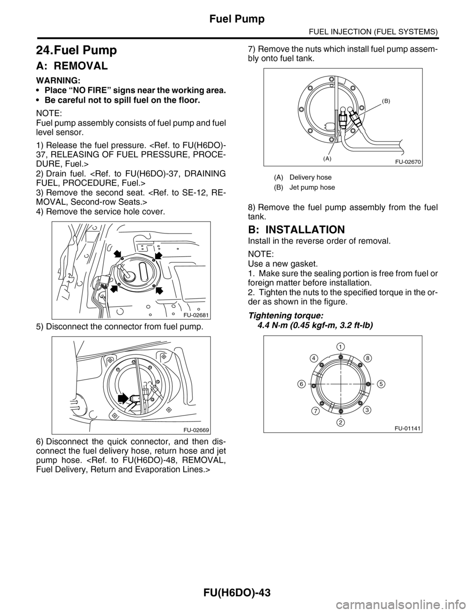
4) Remove the service hole cover.
5) Disconnect the connector from fuel pump.
6) Disconnect the quick connector, and then dis-
connect the fuel delivery hose, return hose and jet
pump hose.
Fuel Delivery, Return and Evaporation Lines.>
7) Remove the nuts which install fuel pump assem-
bly onto fuel tank.
8) Remove the fuel pump assembly from the fuel
tank.
B: INSTALLATION
Install in the reverse order of removal.
NOTE:
Use a new gasket.
1. Make sure the sealing portion is free from fuel or
foreign matter before installation.
2. Tighten the nuts to the specified torque in the or-
der as shown in the figure.
Tightening torque:
4.4 N·m (0.45 kgf-m, 3.2 ft-lb)
FU-02681
FU-02669
(A) Delivery hose
(B) Jet pump hose
FU-02670(A)
(B)
FU-01141
1
2
3
4
56
7
8
Page 1606 of 2453
FU(H6DO)-45
Fuel Level Sensor
FUEL INJECTION (FUEL SYSTEMS)
25.Fuel Level Sensor
A: REMOVAL
WARNING:
•Place “NO FIRE” signs near the working area.
•Be careful not to spill fuel on the floor.
NOTE:
The fuel level sensor is built in fuel pump assembly.
1) Remove the fuel pump assembly.
FU(H6DO)-43, REMOVAL, Fuel Pump.>
2) Disconnect the connector from fuel pump brack-
et.
3) Remove the fuel temperature sensor.
4) Remove the fuel level sensor.
B: INSTALLATION
Install in the reverse order of removal.
(A) Connector
(B) Fuel temperature sensor
(C) Fuel level sensor
Page 1607 of 2453

FU(H6DO)-46
Fuel Sub Level Sensor
FUEL INJECTION (FUEL SYSTEMS)
26.Fuel Sub Level Sensor
A: REMOVAL
WARNING:
•Place “NO FIRE” signs near the working area.
•Be careful not to spill fuel on the floor.
1) Drain fuel.
FUEL, PROCEDURE, Fuel.>
2) Remove the second seat.
MOVAL, Second-row Seats.>
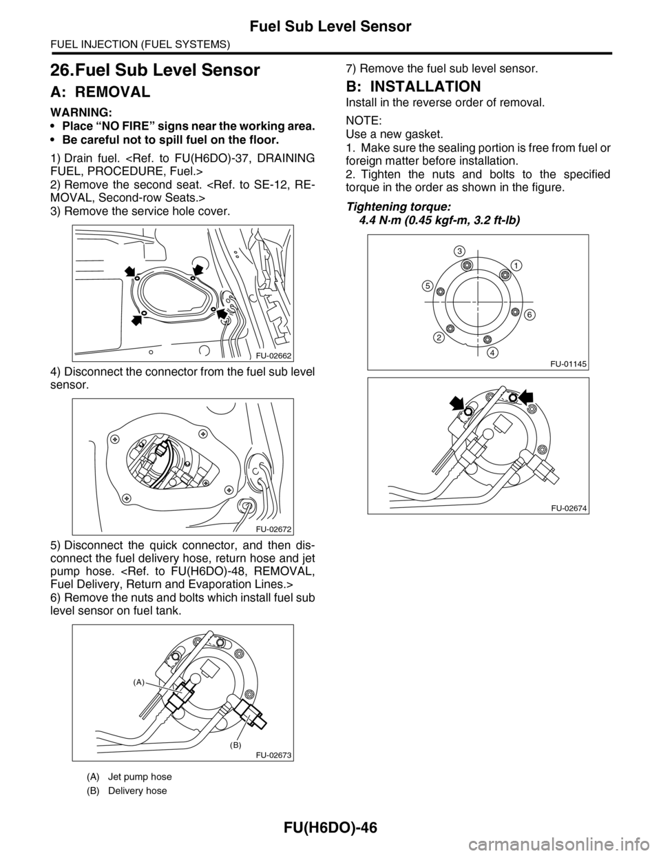
3) Remove the service hole cover.
4) Disconnect the connector from the fuel sub level
sensor.
5) Disconnect the quick connector, and then dis-
connect the fuel delivery hose, return hose and jet
pump hose.
Fuel Delivery, Return and Evaporation Lines.>
6) Remove the nuts and bolts which install fuel sub
level sensor on fuel tank.
7) Remove the fuel sub level sensor.
B: INSTALLATION
Install in the reverse order of removal.
NOTE:
Use a new gasket.
1. Make sure the sealing portion is free from fuel or
foreign matter before installation.
2. Tighten the nuts and bolts to the specified
torque in the order as shown in the figure.
Tightening torque:
4.4 N·m (0.45 kgf-m, 3.2 ft-lb)
(A) Jet pump hose
(B) Delivery hose
FU-02662
FU-02672
FU-02673(B)
(A)
FU-01145
1
6
5
2
4
3
FU-02674
Page 1840 of 2453

IG(H6DO)-5
Spark Plug
IGNITION
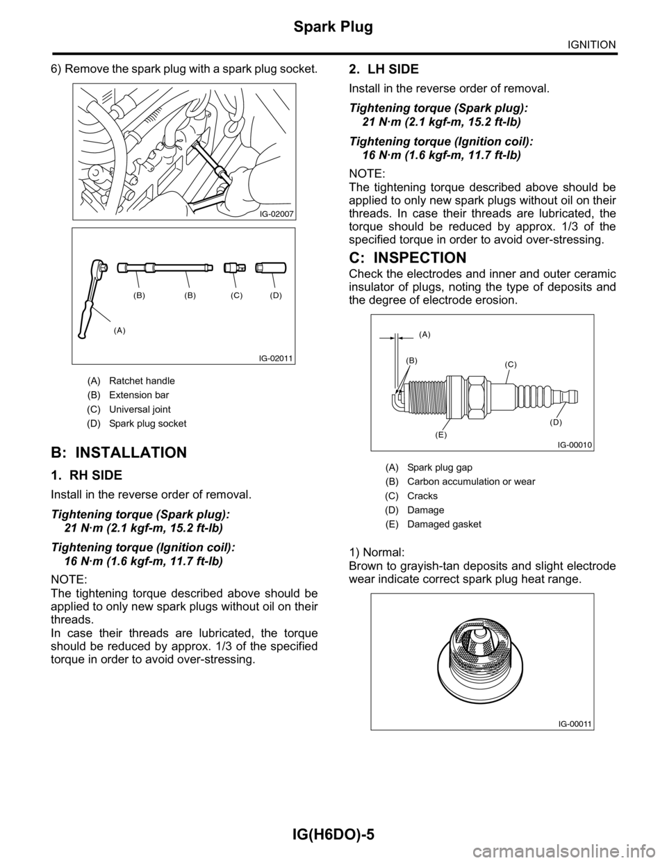
6) Remove the spark plug with a spark plug socket.
B: INSTALLATION
1. RH SIDE
Install in the reverse order of removal.
Tightening torque (Spark plug):
21 N·m (2.1 kgf-m, 15.2 ft-lb)
Tightening torque (Ignition coil):
16 N·m (1.6 kgf-m, 11.7 ft-lb)
NOTE:
The tightening torque described above should be
applied to only new spark plugs without oil on their
threads.
In case their threads are lubricated, the torque
should be reduced by approx. 1/3 of the specified
torque in order to avoid over-stressing.
2. LH SIDE
Install in the reverse order of removal.
Tightening torque (Spark plug):
21 N·m (2.1 kgf-m, 15.2 ft-lb)
Tightening torque (Ignition coil):
16 N·m (1.6 kgf-m, 11.7 ft-lb)
NOTE:
The tightening torque described above should be
applied to only new spark plugs without oil on their
threads. In case their threads are lubricated, the
torque should be reduced by approx. 1/3 of the
specified torque in order to avoid over-stressing.
C: INSPECTION
Check the electrodes and inner and outer ceramic
insulator of plugs, noting the type of deposits and
the degree of electrode erosion.
1) Normal:
Brown to grayish-tan deposits and slight electrode
wear indicate correct spark plug heat range.
(A) Ratchet handle
(B) Extension bar
(C) Universal joint
(D) Spark plug socket
IG-02007
(D)(C)(B)(B)
(A)
IG-02011
(A) Spark plug gap
(B) Carbon accumulation or wear
(C) Cracks
(D) Damage
(E) Damaged gasket
IG-00010
(A)
(B)(C)
(D)
(E)
IG-00011
Page 1842 of 2453
IG(H6DO)-7
Ignition Coil & Ignitor Assembly
IGNITION
3. Ignition Coil & Ignitor Assem-
bly
A: REMOVAL
Direct ignition type has been adopted. Refer to
“Spark Plug” for removal procedure.
IG(H6DO)-4, REMOVAL, Spark Plug.>
B: INSTALLATION
Install in the reverse order of removal.
Tightening torque:
16 N·m (1.6 kgf-m, 11.7 ft-lb)
C: INSPECTION
For inspection procedure, refer to “Diagnostics for
Engine Starting Failure.”
63, IGNITION CONTROL SYSTEM, Diagnostics
for Engine Starting Failure.>
Page 1846 of 2453
IN(H6DO)-4
Air Cleaner Element
INTAKE (INDUCTION)
2. Air Cleaner Element
A: REMOVAL
1) Disconnect the ground cable from battery.
2) Disconnect the connector from mass air flow and
intake air temperature sensor.
3) Remove the clip (A) securing upper side of air
cleaner case.
4) Pull the air cleaner case (rear) backward of the
vehicle, and remove the air cleaner element.
B: INSTALLATION
Install in the reverse order of removal.
NOTE:
Fasten with a clip after inserting the lower tab of
case.
C: INSPECTION
Replace if excessively damaged or dirty.
IN-02143
IN-02144
(A)
IN-02145
Page 1847 of 2453
IN(H6DO)-5
Air Cleaner Case
INTAKE (INDUCTION)
3. Air Cleaner Case
A: REMOVAL
1) Disconnect the ground cable from battery.
2) Remove the air intake duct.
7, REMOVAL, Air Intake Duct.>
3) Disconnect the connector from mass air flow and
intake air temperature sensor.
4) Loosen the clamps (A) which connect the air
cleaner case to intake duct.
5) Remove the clip (B) securing the upper side of
air cleaner case.
6) Remove the air cleaner case (rear) and air
cleaner element.
7) Remove the bolts (A) and nut (B) which secure
the air cleaner case to body.
8) Remove the air cleaner case (front).
B: INSTALLATION
Install in the reverse order of removal.
Tightening torque:
Bolt (A): 6.0 N·m (0.6 kgf-m, 4.4 ft-lb)
Nut (B): 7.5 N·m (0.76 kgf-m, 5.5 ft-lb)
NOTE:
Fasten with a clip after inserting the lower tab of
case.
C: INSPECTION
Check for cracks or loose connections.
IN-02143
IN-02146
(B)
(A)
IN-02148
(B)(A)
IN-02148
(B)(A)
IN-02145