2009 SUBARU TRIBECA Reverse
[x] Cancel search: ReversePage 2236 of 2453
5AT(diag)-119
Diagnostic Procedure with Diagnostic Trouble Code (DTC)
AUTOMATIC TRANSMISSION (DIAGNOSTICS)
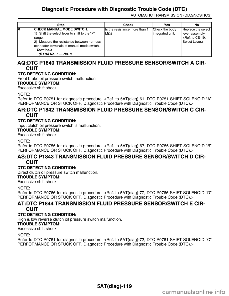
AQ:DTC P1840 TRANSMISSION FLUID PRESSURE SENSOR/SWITCH A CIR-
CUIT
DTC DETECTING CONDITION:
Front brake oil pressure switch malfunction
TROUBLE SYMPTOM:
Excessive shift shock
NOTE:
Refer to DTC P0751 for diagnostic procedure.
AR:DTC P1842 TRANSMISSION FLUID PRESSURE SENSOR/SWITCH C CIR-
CUIT
DTC DETECTING CONDITION:
Input clutch oil pressure switch is malfunction.
TROUBLE SYMPTOM:
Excessive shift shock
NOTE:
Refer to DTC P0756 for diagnostic procedure.
AS:DTC P1843 TRANSMISSION FLUID PRESSURE SENSOR/SWITCH D CIR-
CUIT
DTC DETECTING CONDITION:
Direct clutch oil pressure switch malfunction.
TROUBLE SYMPTOM:
Excessive shift shock
NOTE:
Refer to DTC P0766 for diagnostic procedure.
AT:DTC P1844 TRANSMISSION FLUID PRESSURE SENSOR/SWITCH E CIR-
CUIT
DTC DETECTING CONDITION:
High & low reverse clutch oil pressure switch malfunction.
TROUBLE SYMPTOM:
Excessive shift shock
NOTE:
Refer to DTC P0761 for diagnostic procedure.
8CHECK MANUAL MODE SWITCH.
1) Shift the select lever to shift to the “P”
range.
2) Measure the resistance between harness
connector terminals of manual mode switch.
Te r m i n a l s
(B116) No. 7 — No. 8
Is the resistance more than 1
MΩ?
Check the body
integrated unit.
Replace the select
lever assembly.
Step Check Yes No
Page 2245 of 2453
5AT(diag)-128
General Diagnostic Table
AUTOMATIC TRANSMISSION (DIAGNOSTICS)
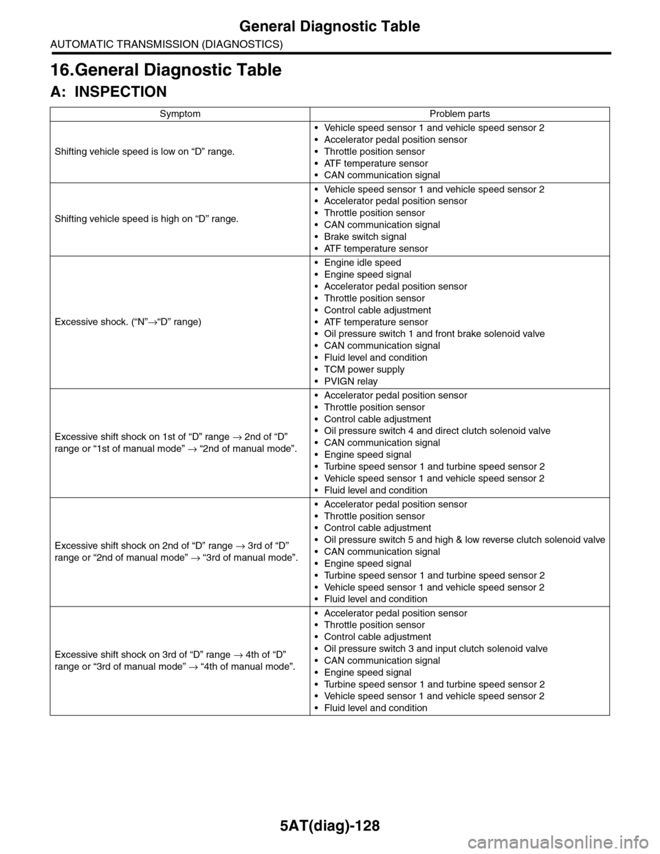
16.General Diagnostic Table
A: INSPECTION
Symptom Problem parts
Shifting vehicle speed is low on “D” range.
•Vehicle speed sensor 1 and vehicle speed sensor 2
•Accelerator pedal position sensor
•Throttle position sensor
•ATF temperature sensor
•CAN communication signal
Shifting vehicle speed is high on “D” range.
•Vehicle speed sensor 1 and vehicle speed sensor 2
•Accelerator pedal position sensor
•Throttle position sensor
•CAN communication signal
•Brake switch signal
•ATF temperature sensor
Excessive shock. (“N”→“D” range)
•Engine idle speed
•Engine speed signal
•Accelerator pedal position sensor
•Throttle position sensor
•Control cable adjustment
•ATF temperature sensor
•Oil pressure switch 1 and front brake solenoid valve
•CAN communication signal
•Fluid level and condition
•TCM power supply
•PVIGN relay
Excessive shift shock on 1st of “D” range → 2nd of “D”
range or “1st of manual mode” → “2nd of manual mode”.
•Accelerator pedal position sensor
•Throttle position sensor
•Control cable adjustment
•Oil pressure switch 4 and direct clutch solenoid valve
•CAN communication signal
•Engine speed signal
•Turbine speed sensor 1 and turbine speed sensor 2
•Vehicle speed sensor 1 and vehicle speed sensor 2
•Fluid level and condition
Excessive shift shock on 2nd of “D” range → 3rd of “D”
range or “2nd of manual mode” → “3rd of manual mode”.
•Accelerator pedal position sensor
•Throttle position sensor
•Control cable adjustment
•Oil pressure switch 5 and high & low reverse clutch solenoid valve
•CAN communication signal
•Engine speed signal
•Turbine speed sensor 1 and turbine speed sensor 2
•Vehicle speed sensor 1 and vehicle speed sensor 2
•Fluid level and condition
Excessive shift shock on 3rd of “D” range → 4th of “D”
range or “3rd of manual mode” → “4th of manual mode”.
•Accelerator pedal position sensor
•Throttle position sensor
•Control cable adjustment
•Oil pressure switch 3 and input clutch solenoid valve
•CAN communication signal
•Engine speed signal
•Turbine speed sensor 1 and turbine speed sensor 2
•Vehicle speed sensor 1 and vehicle speed sensor 2
•Fluid level and condition
Page 2247 of 2453
5AT(diag)-130
General Diagnostic Table
AUTOMATIC TRANSMISSION (DIAGNOSTICS)
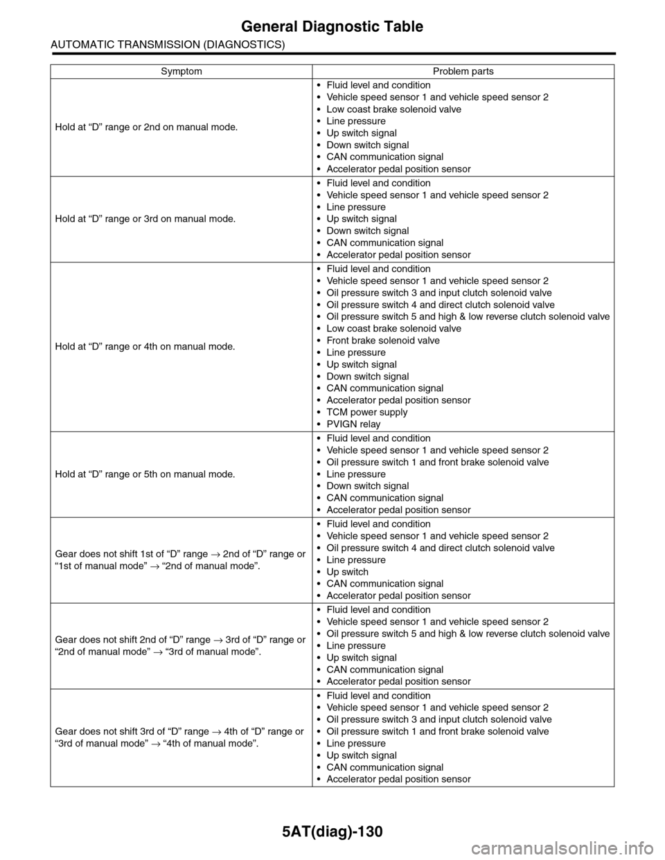
Hold at “D” range or 2nd on manual mode.
•Fluid level and condition
•Vehicle speed sensor 1 and vehicle speed sensor 2
•Low coast brake solenoid valve
•Line pressure
•Up switch signal
•Down switch signal
•CAN communication signal
•Accelerator pedal position sensor
Hold at “D” range or 3rd on manual mode.
•Fluid level and condition
•Vehicle speed sensor 1 and vehicle speed sensor 2
•Line pressure
•Up switch signal
•Down switch signal
•CAN communication signal
•Accelerator pedal position sensor
Hold at “D” range or 4th on manual mode.
•Fluid level and condition
•Vehicle speed sensor 1 and vehicle speed sensor 2
•Oil pressure switch 3 and input clutch solenoid valve
•Oil pressure switch 4 and direct clutch solenoid valve
•Oil pressure switch 5 and high & low reverse clutch solenoid valve
•Low coast brake solenoid valve
•Front brake solenoid valve
•Line pressure
•Up switch signal
•Down switch signal
•CAN communication signal
•Accelerator pedal position sensor
•TCM power supply
•PVIGN relay
Hold at “D” range or 5th on manual mode.
•Fluid level and condition
•Vehicle speed sensor 1 and vehicle speed sensor 2
•Oil pressure switch 1 and front brake solenoid valve
•Line pressure
•Down switch signal
•CAN communication signal
•Accelerator pedal position sensor
Gear does not shift 1st of “D” range → 2nd of “D” range or
“1st of manual mode” → “2nd of manual mode”.
•Fluid level and condition
•Vehicle speed sensor 1 and vehicle speed sensor 2
•Oil pressure switch 4 and direct clutch solenoid valve
•Line pressure
•Up switch
•CAN communication signal
•Accelerator pedal position sensor
Gear does not shift 2nd of “D” range → 3rd of “D” range or
“2nd of manual mode” → “3rd of manual mode”.
•Fluid level and condition
•Vehicle speed sensor 1 and vehicle speed sensor 2
•Oil pressure switch 5 and high & low reverse clutch solenoid valve
•Line pressure
•Up switch signal
•CAN communication signal
•Accelerator pedal position sensor
Gear does not shift 3rd of “D” range → 4th of “D” range or
“3rd of manual mode” → “4th of manual mode”.
•Fluid level and condition
•Vehicle speed sensor 1 and vehicle speed sensor 2
•Oil pressure switch 3 and input clutch solenoid valve
•Oil pressure switch 1 and front brake solenoid valve
•Line pressure
•Up switch signal
•CAN communication signal
•Accelerator pedal position sensor
Symptom Problem parts
Page 2248 of 2453
5AT(diag)-131
General Diagnostic Table
AUTOMATIC TRANSMISSION (DIAGNOSTICS)
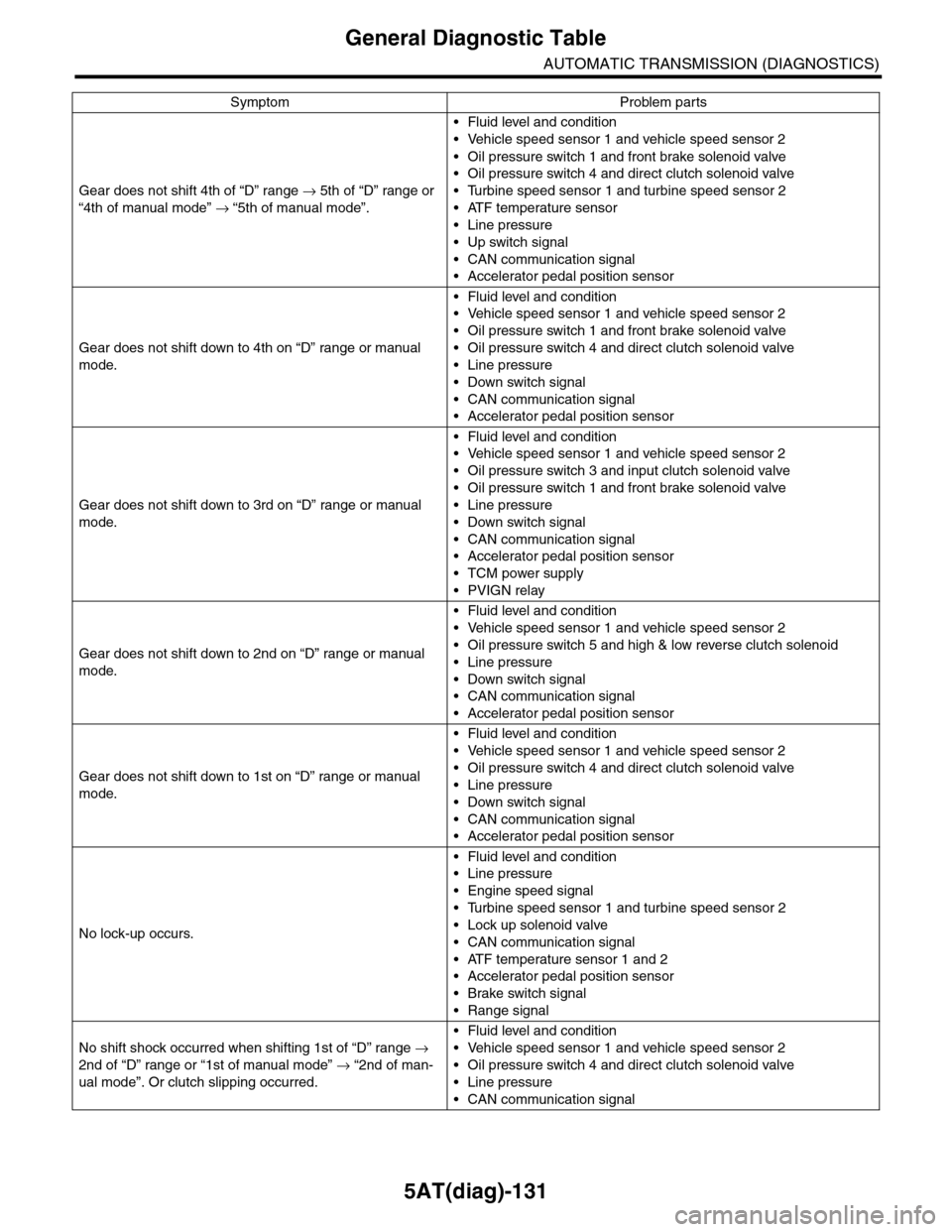
Gear does not shift 4th of “D” range → 5th of “D” range or
“4th of manual mode” → “5th of manual mode”.
•Fluid level and condition
•Vehicle speed sensor 1 and vehicle speed sensor 2
•Oil pressure switch 1 and front brake solenoid valve
•Oil pressure switch 4 and direct clutch solenoid valve
•Turbine speed sensor 1 and turbine speed sensor 2
•ATF temperature sensor
•Line pressure
•Up switch signal
•CAN communication signal
•Accelerator pedal position sensor
Gear does not shift down to 4th on “D” range or manual
mode.
•Fluid level and condition
•Vehicle speed sensor 1 and vehicle speed sensor 2
•Oil pressure switch 1 and front brake solenoid valve
•Oil pressure switch 4 and direct clutch solenoid valve
•Line pressure
•Down switch signal
•CAN communication signal
•Accelerator pedal position sensor
Gear does not shift down to 3rd on “D” range or manual
mode.
•Fluid level and condition
•Vehicle speed sensor 1 and vehicle speed sensor 2
•Oil pressure switch 3 and input clutch solenoid valve
•Oil pressure switch 1 and front brake solenoid valve
•Line pressure
•Down switch signal
•CAN communication signal
•Accelerator pedal position sensor
•TCM power supply
•PVIGN relay
Gear does not shift down to 2nd on “D” range or manual
mode.
•Fluid level and condition
•Vehicle speed sensor 1 and vehicle speed sensor 2
•Oil pressure switch 5 and high & low reverse clutch solenoid
•Line pressure
•Down switch signal
•CAN communication signal
•Accelerator pedal position sensor
Gear does not shift down to 1st on “D” range or manual
mode.
•Fluid level and condition
•Vehicle speed sensor 1 and vehicle speed sensor 2
•Oil pressure switch 4 and direct clutch solenoid valve
•Line pressure
•Down switch signal
•CAN communication signal
•Accelerator pedal position sensor
No lock-up occurs.
•Fluid level and condition
•Line pressure
•Engine speed signal
•Turbine speed sensor 1 and turbine speed sensor 2
•Lock up solenoid valve
•CAN communication signal
•ATF temperature sensor 1 and 2
•Accelerator pedal position sensor
•Brake switch signal
•Range signal
No shift shock occurred when shifting 1st of “D” range →
2nd of “D” range or “1st of manual mode” → “2nd of man-
ual mode”. Or clutch slipping occurred.
•Fluid level and condition
•Vehicle speed sensor 1 and vehicle speed sensor 2
•Oil pressure switch 4 and direct clutch solenoid valve
•Line pressure
•CAN communication signal
Symptom Problem parts
Page 2249 of 2453
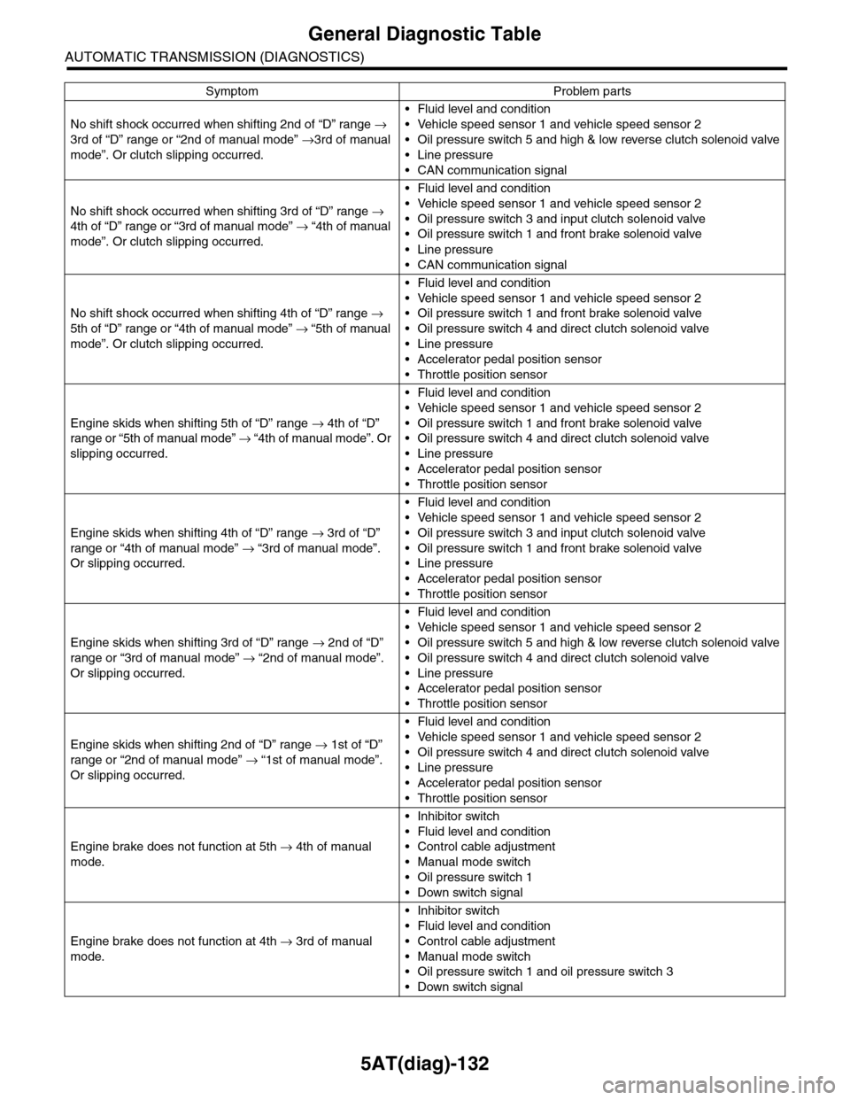
5AT(diag)-132
General Diagnostic Table
AUTOMATIC TRANSMISSION (DIAGNOSTICS)
No shift shock occurred when shifting 2nd of “D” range →
3rd of “D” range or “2nd of manual mode” →3rd of manual
mode”. Or clutch slipping occurred.
•Fluid level and condition
•Vehicle speed sensor 1 and vehicle speed sensor 2
•Oil pressure switch 5 and high & low reverse clutch solenoid valve
•Line pressure
•CAN communication signal
No shift shock occurred when shifting 3rd of “D” range →
4th of “D” range or “3rd of manual mode” → “4th of manual
mode”. Or clutch slipping occurred.
•Fluid level and condition
•Vehicle speed sensor 1 and vehicle speed sensor 2
•Oil pressure switch 3 and input clutch solenoid valve
•Oil pressure switch 1 and front brake solenoid valve
•Line pressure
•CAN communication signal
No shift shock occurred when shifting 4th of “D” range →
5th of “D” range or “4th of manual mode” → “5th of manual
mode”. Or clutch slipping occurred.
•Fluid level and condition
•Vehicle speed sensor 1 and vehicle speed sensor 2
•Oil pressure switch 1 and front brake solenoid valve
•Oil pressure switch 4 and direct clutch solenoid valve
•Line pressure
•Accelerator pedal position sensor
•Throttle position sensor
Engine skids when shifting 5th of “D” range → 4th of “D”
range or “5th of manual mode” → “ 4 t h of ma nua l mo d e” . O r
slipping occurred.
•Fluid level and condition
•Vehicle speed sensor 1 and vehicle speed sensor 2
•Oil pressure switch 1 and front brake solenoid valve
•Oil pressure switch 4 and direct clutch solenoid valve
•Line pressure
•Accelerator pedal position sensor
•Throttle position sensor
Engine skids when shifting 4th of “D” range → 3rd of “D”
range or “4th of manual mode” → “3rd of manual mode”.
Or slipping occurred.
•Fluid level and condition
•Vehicle speed sensor 1 and vehicle speed sensor 2
•Oil pressure switch 3 and input clutch solenoid valve
•Oil pressure switch 1 and front brake solenoid valve
•Line pressure
•Accelerator pedal position sensor
•Throttle position sensor
Engine skids when shifting 3rd of “D” range → 2nd of “D”
range or “3rd of manual mode” → “2nd of manual mode”.
Or slipping occurred.
•Fluid level and condition
•Vehicle speed sensor 1 and vehicle speed sensor 2
•Oil pressure switch 5 and high & low reverse clutch solenoid valve
•Oil pressure switch 4 and direct clutch solenoid valve
•Line pressure
•Accelerator pedal position sensor
•Throttle position sensor
Engine skids when shifting 2nd of “D” range → 1st of “D”
range or “2nd of manual mode” → “1st of manual mode”.
Or slipping occurred.
•Fluid level and condition
•Vehicle speed sensor 1 and vehicle speed sensor 2
•Oil pressure switch 4 and direct clutch solenoid valve
•Line pressure
•Accelerator pedal position sensor
•Throttle position sensor
Engine brake does not function at 5th → 4th of manual
mode.
•Inhibitor switch
•Fluid level and condition
•Control cable adjustment
•Manual mode switch
•Oil pressure switch 1
•Down switch signal
Engine brake does not function at 4th → 3rd of manual
mode.
•Inhibitor switch
•Fluid level and condition
•Control cable adjustment
•Manual mode switch
•Oil pressure switch 1 and oil pressure switch 3
•Down switch signal
Symptom Problem parts
Page 2250 of 2453
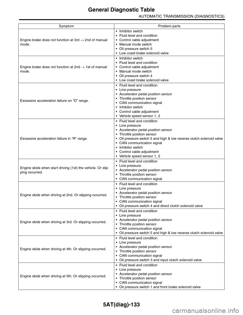
5AT(diag)-133
General Diagnostic Table
AUTOMATIC TRANSMISSION (DIAGNOSTICS)
Engine brake does not function at 3rd → 2nd of manual
mode.
•Inhibitor switch
•Fluid level and condition
•Control cable adjustment
•Manual mode switch
•Oil pressure switch 5
•Low coast brake solenoid valve
Engine brake does not function at 2nd → 1st of manual
mode.
•Inhibitor switch
•Fluid level and condition
•Control cable adjustment
•Manual mode switch
•Oil pressure switch 4
•Low coast brake solenoid valve
Excessive acceleration failure on “D” range.
•Fluid level and condition
•Line pressure
•Accelerator pedal position sensor
•Throttle position sensor
•CAN communication signal
•Inhibitor switch
•Control cable adjustment
•Vehicle speed sensor 1, 2
Excessive acceleration failure in “R” range.
•Fluid level and condition
•Line pressure
•Accelerator pedal position sensor
•Throttle position sensor
•Oil pressure switch 5 and high & low reverse clutch solenoid valve
•CAN communication signal
•Inhibitor switch
•Control cable adjustment
•Vehicle speed sensor 1, 2
Engine skids when start driving (1st) the vehicle. Or slip-
ping occurred.
•Fluid level and condition
•Line pressure
•Accelerator pedal position sensor
•Throttle position sensor
•CAN communication signal
Engine skids when driving at 2nd. Or slipping occurred.
•Fluid level and condition
•Line pressure
•Accelerator pedal position sensor
•Throttle position sensor
•CAN communication signal
•Oil pressure switch 4 and direct clutch solenoid valve
Engine skids when driving at 3rd. Or slipping occurred.
•Fluid level and condition
•Line pressure
•Accelerator pedal position sensor
•Throttle position sensor
•CAN communication signal
•Oil pressure switch 5 and high & low reverse clutch solenoid valve
Engine skids when driving at 4th. Or slipping occurred.
•Fluid level and condition
•Line pressure
•Accelerator pedal position sensor
•Throttle position sensor
•CAN communication signal
•Oil pressure switch 3 and input clutch solenoid valve
Engine skids when driving at 5th. Or slipping occurred.
•Fluid level and condition
•Line pressure
•Accelerator pedal position sensor
•Throttle position sensor
•CAN communication signal
•Oil pressure switch 1 and front brake solenoid valve
Symptom Problem parts
Page 2277 of 2453
![SUBARU TRIBECA 2009 1.G Service Workshop Manual CS-25
Select Lever
CONTROL SYSTEMS
D: ASSEMBLY
1) Clean all the parts before assembly.
2) Apply grease [Multemp AC-D, and SH-W or
equivalent] to each part. <Ref. to CS-2, AT SE-
LECT LE SUBARU TRIBECA 2009 1.G Service Workshop Manual CS-25
Select Lever
CONTROL SYSTEMS
D: ASSEMBLY
1) Clean all the parts before assembly.
2) Apply grease [Multemp AC-D, and SH-W or
equivalent] to each part. <Ref. to CS-2, AT SE-
LECT LE](/manual-img/17/7322/w960_7322-2276.png)
CS-25
Select Lever
CONTROL SYSTEMS
D: ASSEMBLY
1) Clean all the parts before assembly.
2) Apply grease [Multemp AC-D, and SH-W or
equivalent] to each part.
tion.>
3) Assemble in the reverse order of disassembly.
NOTE:
•Refer to “COMPONENT” for each tightening
torque.
•When pressing in the shift position pin, insert
from the left side of the vehicle.
•Affix the harness of the shift button switch and
the mode change switch at the marked positions.
•Connect the terminals of all switches to the re-
spective connectors.
4) After completing installation, shift the select le-
ver from the “P” range to the “D” range, then check
whether or not the selection indicator in the combi-
nation meter and the select lever position matches.
Also check whether the pointer and position mark
matches, and what the operating force is.
E: INSPECTION
1) Inspect the removed parts by comparing with
new ones for deformation, damage and wear. Re-
pair or replace if defective.
2) Confirm the select lever operating condition be-
fore assembly. Normal if it operates smoothly. CS-00641
(A) Mode change switch (color code: Yellow)
(B) Shift button switch (color code: Brown)
(C) Mode change switch and shift button switch
ground (color code: White)
(D) Shift up switch (color code: Green)
(E) Shift up switch (color code: Gray)
(F) Shift up/down switch ground (color code: Blue)
(G) “P” range switch (wire color: Red)
(H) Shift lock solenoid (color code: Blue)
(I) Shift lock solenoid (color code: Black)
(J) Indicator lamp (color code: Blue)
CS-00642
5432112 11 10 9876
(J)
(J)(F)(E)(D)(A)(B)(C)
(H) (G)(I)
Page 2280 of 2453
CS-28
Select Cable
CONTROL SYSTEMS
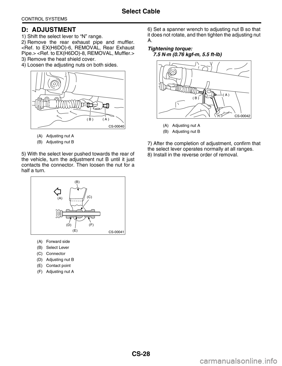
D: ADJUSTMENT
1) Shift the select lever to “N” range.
2) Remove the rear exhaust pipe and muffler.
3) Remove the heat shield cover.
4) Loosen the adjusting nuts on both sides.
5) With the select lever pushed towards the rear of
the vehicle, turn the adjustment nut B until it just
contacts the connector. Then loosen the nut for a
half a turn.
6) Set a spanner wrench to adjusting nut B so that
it does not rotate, and then tighten the adjusting nut
A.
Tightening torque:
7.5 N·m (0.76 kgf-m, 5.5 ft-lb)
7) After the completion of adjustment, confirm that
the select lever operates normally at all ranges.
8) Install in the reverse order of removal.
(A) Adjusting nut A
(B) Adjusting nut B
(A) Forward side
(B) Select Lever
(C) Connector
(D) Adjusting nut B
(E) Contact point
(F) Adjusting nut A
CS-00040
( A )( B )
CS-00041
(A)
(B)
(C)
(D)
(E)
(F)
(A) Adjusting nut A
(B) Adjusting nut B
CS-00042
( A )( B )