Page 892 of 2453

PS-12
Steering Wheel
POWER ASSISTED SYSTEM (POWER STEERING)
2. Steering Wheel
A: REMOVAL
1) Disconnect the ground cable from the battery.
2) Set the tire to the straight–ahead position.
3) Remove the airbag module.
MOVAL, Driver’s Airbag Module.>
WARNING:
Always refer to “Air Bag System” before per-
forming service on the air bag modules.
to AB-4, CAUTION, General Description.>
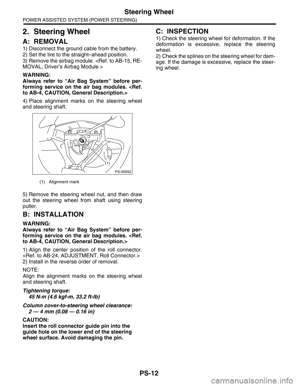
4) Place alignment marks on the steering wheel
and steering shaft.
5) Remove the steering wheel nut, and then draw
out the steering wheel from shaft using steering
puller.
B: INSTALLATION
WARNING:
Always refer to “Air Bag System” before per-
forming service on the air bag modules.
to AB-4, CAUTION, General Description.>
1) Align the center position of the roll connector.
2) Install in the reverse order of removal.
NOTE:
Align the alignment marks on the steering wheel
and steering shaft.
Tightening torque:
45 N·m (4.6 kgf-m, 33.2 ft-lb)
Column cover-to-steering wheel clearance:
2 — 4 mm (0.08 — 0.16 in)
CAUTION:
Insert the roll connector guide pin into the
guide hole on the lower end of the steering
wheel surface. Avoid damaging the pin.
C: INSPECTION
1) Check the steering wheel for deformation. If the
deformation is excessive, replace the steering
wheel.
2) Check the splines on the steering wheel for dam-
age. If the damage is excessive, replace the steer-
ing wheel.
(1) Alignment mark
(1)
PS-00552
Page 918 of 2453
PS-38
Pipe Assembly
POWER ASSISTED SYSTEM (POWER STEERING)
7) Disconnect the suction hose and pressure hose
from oil pump.
8) Disconnect the suction hose and return hose
from the reservoir tank.
9) Remove the oil cooler pipe.
10) Remove the hose bracket and take out the
hose assembly from vehicle.
B: INSTALLATION
1) Install in the reverse order of removal.
Tightening torque:
COMPONENT, General Description.>
2) Fill with the specified fluid.
CAUTION:
Never start the engine before feeding the fluid
otherwise the vane pump might be seized.
3) Finally, check the clearance between pipes or
hoses as shown in the figure indicated in “General
Diagnostic Table”.
OF CLEARANCE, INSPECTION, General Diag-
nostic Table.>
(1) Suction hose
(2) Pressure hose
(1) Reservoir tank
(2) Suction hose
(3) Return hose
PS-00736
(1)
(2)
PS-00737(3)
(2)
(1)
(1) Hose ASSY
(2) Hose bracket
PS-00738
PS-00739
(2)
(1)
Page 921 of 2453

PS-41
Oil Pump
POWER ASSISTED SYSTEM (POWER STEERING)
7. Oil Pump
A: REMOVAL
1) Disconnect the ground cable from the battery.
2) Remove the air intake duct.
7, REMOVAL, Air Intake Duct.>
3) Remove the pulley belt cover.
4) Remove the V-belts.
5) Disconnect the connector from power steering
pump switch.
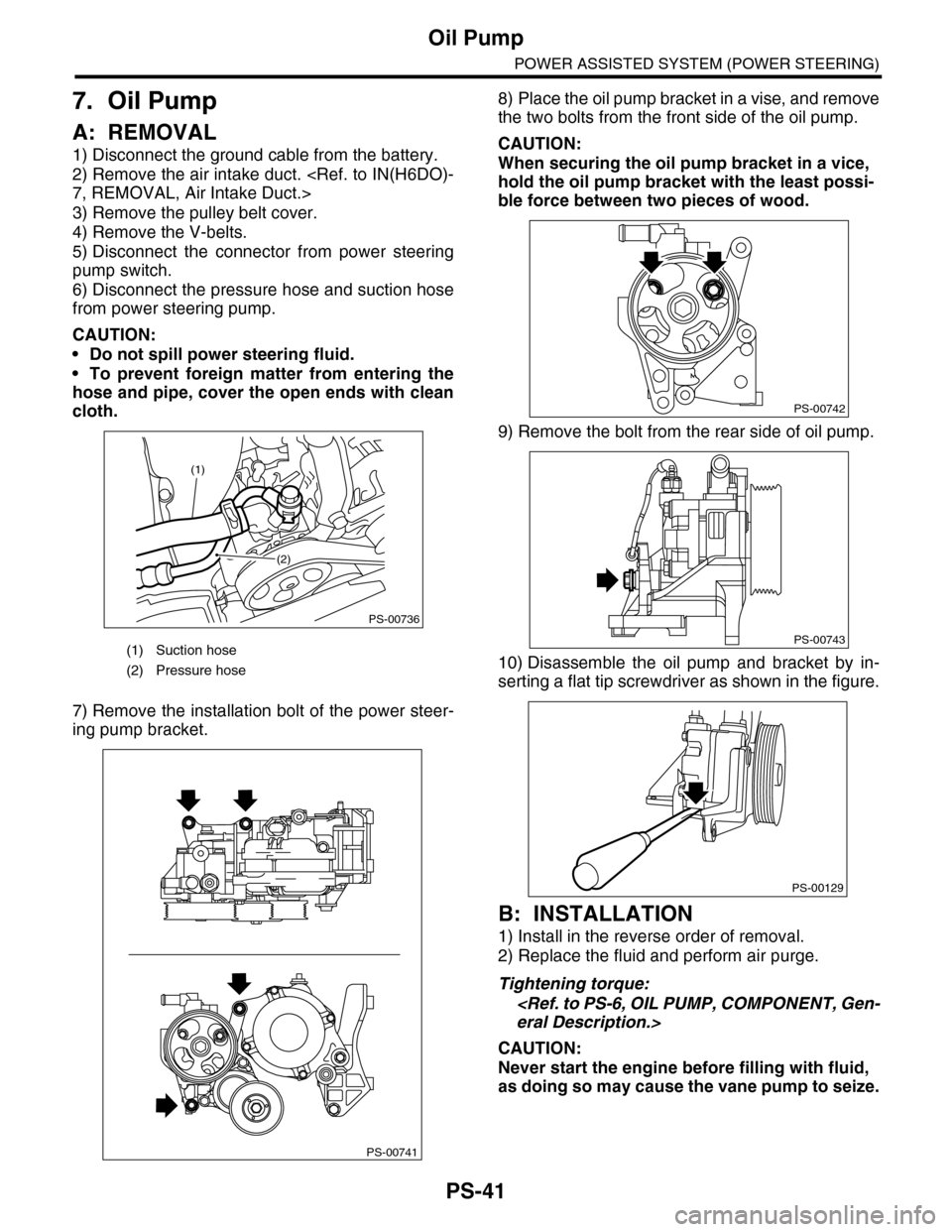
6) Disconnect the pressure hose and suction hose
from power steering pump.
CAUTION:
•Do not spill power steering fluid.
•To prevent foreign matter from entering the
hose and pipe, cover the open ends with clean
cloth.
7) Remove the installation bolt of the power steer-
ing pump bracket.
8) Place the oil pump bracket in a vise, and remove
the two bolts from the front side of the oil pump.
CAUTION:
When securing the oil pump bracket in a vice,
hold the oil pump bracket with the least possi-
ble force between two pieces of wood.
9) Remove the bolt from the rear side of oil pump.
10) Disassemble the oil pump and bracket by in-
serting a flat tip screwdriver as shown in the figure.
B: INSTALLATION
1) Install in the reverse order of removal.
2) Replace the fluid and perform air purge.
Tightening torque:
eral Description.>
CAUTION:
Never start the engine before filling with fluid,
as doing so may cause the vane pump to seize.
(1) Suction hose
(2) Pressure hose
PS-00736
(1)
(2)
PS-00741
PS-00742
PS-00743
PS-00129
Page 922 of 2453

PS-42
Oil Pump
POWER ASSISTED SYSTEM (POWER STEERING)
C: DISASSEMBLY
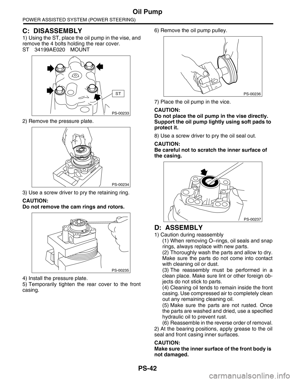
1) Using the ST, place the oil pump in the vise, and
remove the 4 bolts holding the rear cover.
ST 34199AE020 MOUNT
2) Remove the pressure plate.
3) Use a screw driver to pry the retaining ring.
CAUTION:
Do not remove the cam rings and rotors.
4) Install the pressure plate.
5) Temporarily tighten the rear cover to the front
casing.
6) Remove the oil pump pulley.
7) Place the oil pump in the vice.
CAUTION:
Do not place the oil pump in the vise directly.
Support the oil pump lightly using soft pads to
protect it.
8) Use a screw driver to pry the oil seal out.
CAUTION:
Be careful not to scratch the inner surface of
the casing.
D: ASSEMBLY
1) Caution during reassembly
(1) When removing O–rings, oil seals and snap
rings, always replace with new parts.
(2) Thoroughly wash the parts and allow to dry.
Make sure the parts do not come into contact
with cleaning oil or dust.
(3) The reassembly must be performed in a
clean place. Make sure lint or other foreign ob-
jects do not stick to parts.
(4) Cleaning oil tends to remain inside the front
casing. Use compressed air to completely clean
out any remaining cleaning oil.
(5) Make sure the parts are not rusted. Once
the parts are washed and dried, use a specified
hydraulic oil to prevent rust.
(6) Reassemble in the reverse order of removal.
2) At the bearing positions, apply grease to the oil
seal and front casing inner surfaces.
CAUTION:
Make sure the inner surface of the front body is
not damaged.
PS-00233
ST
PS-00234
PS-00235
PS-00236
PS-00237
Page 927 of 2453
PS-47
Reservoir Tank
POWER ASSISTED SYSTEM (POWER STEERING)
8. Reservoir Tank
A: REMOVAL
1) Drain fluid from the reservoir tank.
2) Disconnect the hose from reservoir tank.
CAUTION:
To prevent foreign matter from entering the
hose and pipe, cover the open ends of them
with clean cloth.
3) Remove the bolt and remove the reservoir tank
from the body.
CAUTION:
Do not separate the reserve tank and bracket.
B: INSTALLATION
1) Install in the reverse order of removal.
2) Replenish power steering fluid up to the speci-
fied level.
Tightening torque:
33 N·m (3.37 kgf-m, 24.3 ft-lb)
C: INSPECTION
Check the reservoir tank for cracks, breakage or
damage. If a failure is found, replace the reservoir
tank.
(1) Reservoir tank
(2) Suction hose
(3) Return hose
PS-00744(3)
(2)
(1)
Page 941 of 2453
RS-8
Rear Stabilizer
REAR SUSPENSION
3. Rear Stabilizer
A: REMOVAL
1) Lift-up the vehicle, and then remove the rear
wheels.
2) Remove the stabilizer link.
3) Remove the stabilizer link.
B: INSTALLATION
NOTE:
•Use a new flange nut (with WAX).
•Always tighten the stabilizer bushing in the state
where the vehicle is at curb weight and the wheels
are in full contact with the ground.
Install in the reverse order of removal.
Tightening torque:
Stabilizer link
60 N·m (6.1 kgf-m, 44 ft-lb)
Stabilizer clamp
35 N·m (3.6 kgf-m, 25.8 ft-lb)
C: INSPECTION
1) Check the bushing for cracks, fatigue or dam-
age.
2) Check the stabilizer link for damage.
RS-00178
RS-00179
Page 942 of 2453
RS-9
Rear Trailing Link
REAR SUSPENSION
4. Rear Trailing Link
A: REMOVAL
1) Lift-up the vehicle, and then remove the rear
wheels.
2) Remove the bracket, and remove the parking
brake cable from the guide.
3) Remove the ABS wheel speed sensor harness
from the trailing link.
4) Remove the trailing link.
B: INSTALLATION
NOTE:
•Be sure to use a new self-locking nut.
•Always tighten the stabilizer bushing in the state
where the vehicle is at curb weight and the wheels
are in full contact with the ground.
Install in the reverse order of removal.
Tightening torque:
Trailing link
120 N·m (12.2 kgf-m, 89 ft-lb)
Parking Brake Cable bracket
33 N·m (3.4 kgf-m, 24 ft-lb)
C: DISASSEMBLY
Using the ST and a pipe, press the bushing out.
ST 20099PA010 INSTALLER & REMOVER
(1) Guide
RS-00180
(1)
RS-00181
(1) 39 mm dia., 50 mm long pipe
(2) Trailing link
RS-00182
ST
(2)
(1)
Page 944 of 2453
RS-11
Upper Arm
REAR SUSPENSION
5. Upper Arm
A: REMOVAL
1) Lift-up the vehicle, and then remove the rear
wheels.
2) Remove the bolts, and then remove the upper
arm.
B: INSTALLATION
NOTE:
•Use a new self-locking nut.
•Always tighten the stabilizer bushing in the state
where the vehicle is at curb weight and the wheels
are in full contact with the ground.
1) Install in the reverse order of removal.
2) Inspect the wheel alignment and adjust it if nec-
essary.
Tightening torque:
Upper arm to Rear sub frame
150 N·m (15.3 kgf-m, 111 ft-lb)
Upper arm to Rear housing
120 N·m (12.2 kgf-m, 89 ft-lb)
C: INSPECTION
1) Visually check the upper arm for damage and
deformation.
2) Visually check the bushing for crack, damage
and fatigue.
RS-00184