Page 900 of 2453
PS-20
Steering Gearbox
POWER ASSISTED SYSTEM (POWER STEERING)
4) Remove the small clip from the boot using pliers,
and then move the boot to tie-rod end side.
5) Using a flat tip screwdriver, remove the band
from boot.
NOTE:
Replace the boot if there is damage, cracks or de-
terioration.
6) Using the ST, loosen the lock nut.
ST 926230000 SPANNER
7) Tighten the adjusting screw until it can no longer
be tightened.
8) While securing the rack with a 22 mm wrench,
remove the tie-rod using 32 mm (1.26 in) wrench or
adjustable wrench.
9) Loosen the adjusting screw, and remove the
spring and sleeve.
10) Remove the two bolts securing valve assem-
bly.
(1) Clip
(1) Band
(1) Lock nut
PS-00053
PS-00509
(1)
PS-00494
ST
(1)
(1) Adjusting screw
(1) Holder
PS-00495
(1)
PS-00058
PS-00116
Page 902 of 2453
PS-22
Steering Gearbox
POWER ASSISTED SYSTEM (POWER STEERING)
2. CONTROL VALVE
1) Disconnect the pipes A and B from gearbox.
2) Secure the gearbox removed from vehicle in a
vise using ST.
ST1 926200000 STAND
ST2 34199AG000 BOSS D
CAUTION:
Secure the gearbox in a vise using ST as shown
in the figure. Do not secure the gearbox without
this ST.
3) Using the ST, loosen the lock nut.
ST 926230000 SPANNER
4) Tighten the adjusting screw until it can no longer
be tightened.
5) Loosen the adjusting screw, and remove the
spring and sleeve.
6) Remove the two bolts securing valve assembly.
7) Carefully draw out the input shaft and remove
the valve assembly.
8) Put a vinyl tape around the spline portion, and
slide the dust cover to remove.
(1) Clamp
(1) Lock nut
(1) Adjusting screw
PS-00492
(1)
ST1
ST2
PS-00494
ST
(1)
PS-00495
(1)
(1) Dust cover
PS-00116
PS-00143
PS-00144
(1)
Page 906 of 2453

PS-26
Steering Gearbox
POWER ASSISTED SYSTEM (POWER STEERING)
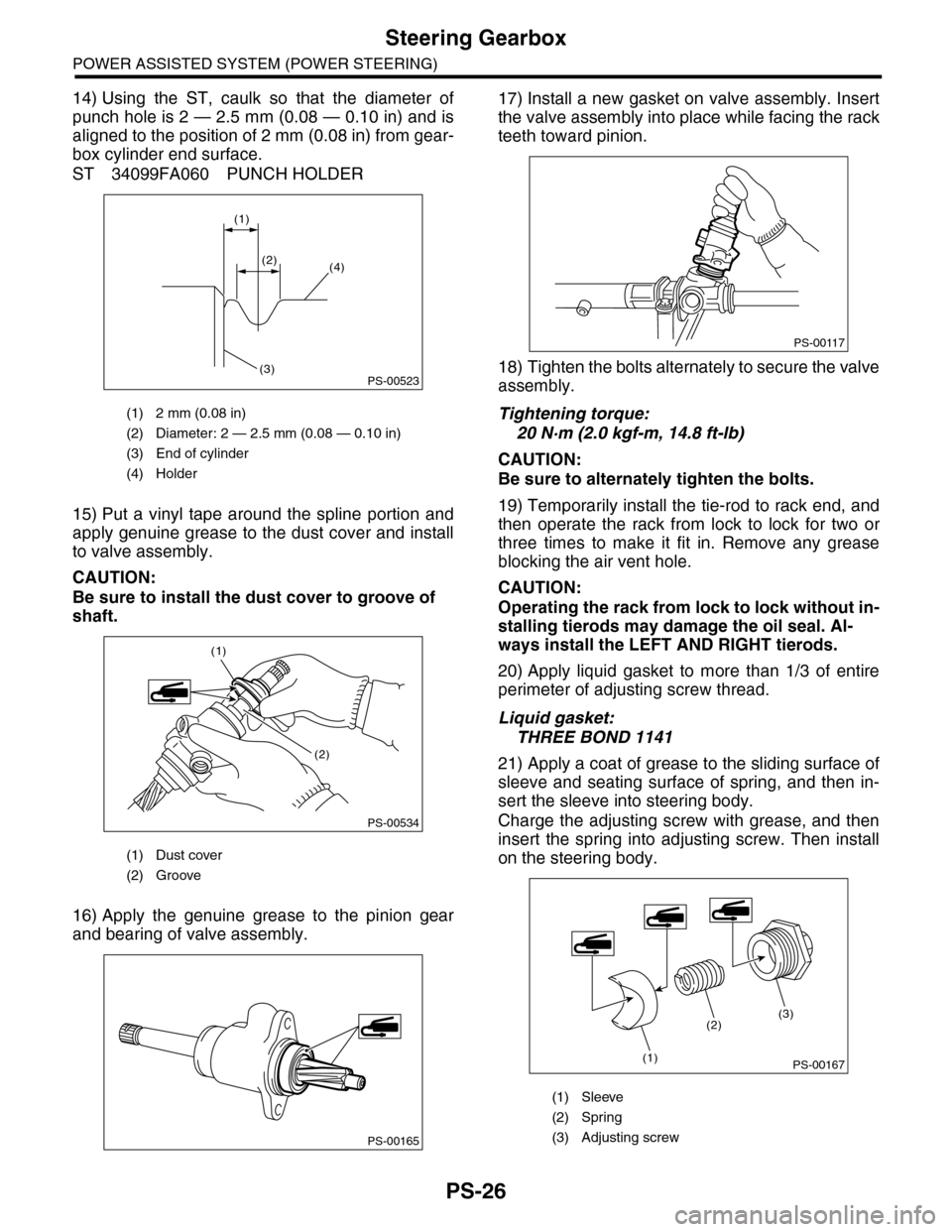
14) Using the ST, caulk so that the diameter of
punch hole is 2 — 2.5 mm (0.08 — 0.10 in) and is
aligned to the position of 2 mm (0.08 in) from gear-
box cylinder end surface.
ST 34099FA060 PUNCH HOLDER
15) Put a vinyl tape around the spline portion and
apply genuine grease to the dust cover and install
to valve assembly.
CAUTION:
Be sure to install the dust cover to groove of
shaft.
16) Apply the genuine grease to the pinion gear
and bearing of valve assembly.
17) Install a new gasket on valve assembly. Insert
the valve assembly into place while facing the rack
teeth toward pinion.
18) Tighten the bolts alternately to secure the valve
assembly.
Tightening torque:
20 N·m (2.0 kgf-m, 14.8 ft-lb)
CAUTION:
Be sure to alternately tighten the bolts.
19) Temporarily install the tie-rod to rack end, and
then operate the rack from lock to lock for two or
three times to make it fit in. Remove any grease
blocking the air vent hole.
CAUTION:
Operating the rack from lock to lock without in-
stalling tierods may damage the oil seal. Al-
ways install the LEFT AND RIGHT tierods.
20) Apply liquid gasket to more than 1/3 of entire
perimeter of adjusting screw thread.
Liquid gasket:
THREE BOND 1141
21) Apply a coat of grease to the sliding surface of
sleeve and seating surface of spring, and then in-
sert the sleeve into steering body.
Charge the adjusting screw with grease, and then
insert the spring into adjusting screw. Then install
on the steering body.
(1) 2 mm (0.08 in)
(2) Diameter: 2 — 2.5 mm (0.08 — 0.10 in)
(3) End of cylinder
(4) Holder
(1) Dust cover
(2) Groove
PS-00523
(1)
(2)(4)
(3)
PS-00534
(1)
(2)
PS-00165
(1) Sleeve
(2) Spring
(3) Adjusting screw
PS-00117
PS-00167
(2)
(1)
(3)
Page 907 of 2453

PS-27
Steering Gearbox
POWER ASSISTED SYSTEM (POWER STEERING)
22) Tighten the adjusting screw to the specified
torque.
Tightening torque:
3.9 N·m (0.4 kgf-m, 2.9 ft-lb)
23) Tighten the adjusting screw to the specified
torque, then loosen it 20°.
24) Remove the tie–rod.
25) Adjust the turning resistance of gearbox so that
it is within specification using adjusting screw.
GEARBOX, INSPECTION, Steering Gearbox.>
26) Apply liquid gasket to lock nut and install it into
adjusting screw. While holding the adjusting screw
with wrench, tighten the lock nut using ST.
Liquid gasket:
THREE BOND 1141
ST 926230000 SPANNER
Tightening torque (lock nut):
25 N·m (2.5 kgf-m, 18.1 ft-lb)
NOTE:
Hold the adjusting screw with a wrench to prevent it
from turning while tightening lock nut.
27) Extend the rack approx. 40 mm (1.57 in) from
steering body.
28) Install the tie-rod and new lock washer into
rack.
Tightening torque:
130 N·m (13.3 kgf-m, 95.9 ft-lb)
29) Bend the lock washer and caulk it.
CAUTION:
Be careful not to scratch the rack when caulk-
ing lock washer.
30) Apply a coat of grease to the tie–rod groove,
and then install the boot to the housing.
CAUTION:
Right side boot has groove for identification, be
sure to install the right and left of boot.
(1) Lock washer
(2) Approx. 40 mm (1.57 in)
PS-00439
(2)
(1)
(1) Lock washer
(1) Right side boot
(2) Groove for identification
PS-00093
PS-00524
(2)
(1)
Page 908 of 2453

PS-28
Steering Gearbox
POWER ASSISTED SYSTEM (POWER STEERING)
NOTE:
Make sure that the boot is installed without unusual
inflation or deflation.
31) Install a new boot band. Using band clamp pli-
ers, caulk it so that the clearance of caulking por-
tion becomes 2mm (0. 079 in) or less.
32) Fix the boot end with small clip.
33) After installing, check that the boot end is in-
stalled to the groove of the tie–rod.
34) If the tie-rod end has been removed, screw in
lock nut and tie-rod end to the screwed portion of
tie–rod, and tighten the lock nut temporarily in a po-
sition as shown in the figure.
Installed tie-rod length L:
31 mm (1.22 in)
35) Inspect the gearbox as follows:
Holding the “A” tie–rod end, repeat movement from
lock to lock two or three times as quickly as possi-
ble.
Holding the “B” tie–rod end, turn a few times as
slowly as possible.
Finally, make sure that the boot is installed in the
specified position without inflating.
36) Remove the gearbox from ST.
ST1 926200000 STAND
ST2 34199AG000 BOSS D
(A) Boot band
(B) Less than 2 mm (0.079 in)
PS-00194
PS-00499
(A)
(B)
(1) Clip
PS-00053
PS-00097
L
PS-00098
BA
Page 912 of 2453

PS-32
Steering Gearbox
POWER ASSISTED SYSTEM (POWER STEERING)
25) Adjust the turning resistance of gearbox so that
it is within specification using adjusting screw.
GEARBOX, INSPECTION, Steering Gearbox.>
26) Apply liquid gasket to lock nut and install it into
adjusting screw. While holding the adjusting screw
with wrench, tighten the lock nut using ST.
Liquid gasket:
THREE BOND 1141
ST 926230000 SPANNER
Tightening torque (lock nut):
25 N·m (2.5 kgf-m, 18.1 ft-lb)
NOTE:
Hold the adjusting screw with a wrench to prevent it
from turning while tightening lock nut.
27) Remove the gearbox from ST.
ST1 926200000 STAND
ST2 34199AG000 BOSS D
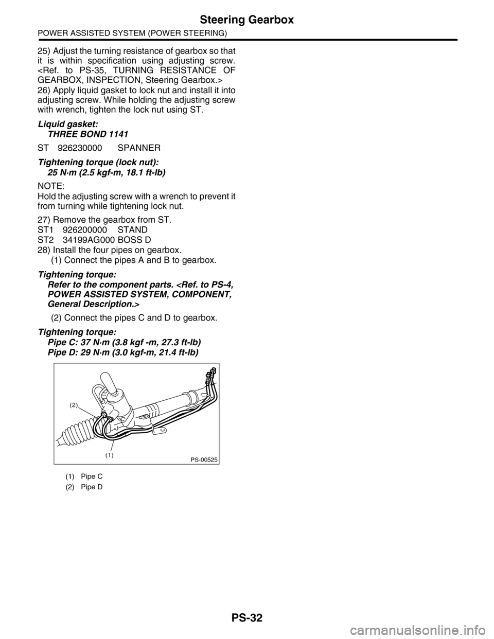
28) Install the four pipes on gearbox.
(1) Connect the pipes A and B to gearbox.
Tightening torque:
Refer to the component parts.
POWER ASSISTED SYSTEM, COMPONENT,
General Description.>
(2) Connect the pipes C and D to gearbox.
Tightening torque:
Pipe C: 37 N·m (3.8 kgf -m, 27.3 ft-lb)
Pipe D: 29 N·m (3.0 kgf-m, 21.4 ft-lb)
(1) Pipe C
(2) Pipe D
PS-00525(1)
(2)
Page 916 of 2453

PS-36
Steering Gearbox
POWER ASSISTED SYSTEM (POWER STEERING)
1) Lift-up the vehicle.
2) If a fluid leak is found, clean the fluid completely
from the suspect area, and turn the steering wheel
approx. 30 to 40 times to the left and right from lock
to lock, with the engine running, and check again
for leaks immediately, and also after a few hours
have passed.
3) Cause and solution for oil leakage from “a”
The oil seal is damaged. Replace the valve assem-
bly with a new one.
4) Cause and solution for oil leakage from “b”.
The torsion bar O–ring is damaged. Replace the
valve assembly with a new one.
5) Cause and solution for oil leakage from “c”.
The oil seal is damaged. Replace the valve assem-
bly or oil seal with a new one.
6) Cause and solution for oil leakage from “d”.
The pipe is damaged. Replace the faulty pipe or O-
ring.
7) Cause and solution for oil leakage from “g”.
The hose is damaged. Replace the hose with a
new one.
8) If leak is other than a, b, c, d or g, or if oil is leak-
ing from gearbox, move the right and left boots to-
ward tie-rod end side, respectively, with the
gearbox mounted to the vehicle, and remove fluid
from surrounding portions. Then, turn the steering
wheel from lock to lock about thirty to forty times
with the engine running, and make comparison of
the leaked portion immediately after and several
hours after this operation.
(1) Leakage from “e”
The cylinder seal is damaged. Replace the rack
bushing with a new one.
(2) Leakage from “f”
There are two possible causes. Perform the fol-
lowing step first. Remove the pipe assembly B
from the valve housing, and close the circuit us-
ing ST.
ST 926420000 PLUG
Turn the steering wheel from lock to lock ap-
prox. 30 to 40 times with the engine running,
then inspect the leaked portion immediately af-
ter and several hours after this operation.
•If leakage from “f” is noted again:
The oil seal of pinion & valve assembly is dam-
aged. Replace the pinion & valve assembly with a
new one. Or replace the oil seal and the parts that
are damaged during disassembly with new ones.
•If oil stops leaking from “f”:
The oil seal of rack housing is damaged. Replace
the oil seal and parts that are damaged during dis-
assembly with new ones.
F: ADJUSTMENT
1) Adjust the front toe.
SPECTION, Wheel Alignment.>
Standard of front toe:
IN 3 — OUT 3 mm (IN 0.12 — OUT 0.12 in)
2) Adjust the steering angle of the wheels.
Specification of steering angle:
3) If the steering wheel spokes are not horizontal
when wheels are set in the straight ahead position,
or error is more than 5° on the periphery of the
steering wheel, correctly re-install the steering
wheel.
4) If the steering wheel spokes are not horizontal
with vehicle set in the straight ahead position after
this adjustment, correct it by turning the right and
left tie–rods in the opposite direction from each oth-
er by the same angle.
(1) Lock nut
Inner wheel 37.0°±1.5°
Outer wheel 32.0°±1.5°
(1) Within 5°
PS-00107
PS-00513
(1)
Page 917 of 2453
PS-37
Pipe Assembly
POWER ASSISTED SYSTEM (POWER STEERING)
6. Pipe Assembly
A: REMOVAL
1) Disconnect the ground cable from the battery.
2) Lift-up the vehicle, and then remove the front
crossmember support plate and jack-up plate.
3) Remove the one pipe joint at the center of the
gearbox, and connect the vinyl hose to the pipe and
the joint. Discharge the fluid by turning the steering
wheel fully clockwise and counterclockwise. Dis-
charge the fluid similarly from other pipes.
4) Remove the clamp E from return hose and pres-
sure hose.
5) Disconnect the pipe D from return hose and pipe
C from pressure hose.
6) Remove the air intake duct.
7, REMOVAL, Air Intake Duct.>
(1) Front crossmember support plate
(2) Jack–up plate
(1) Pipe A
(2) Pipe B
(2)(1)
(1)
FS-00200
(2)
PS-00553
(1)
(1) Return hose
(2) Pressure hose
(3) Clamp E
(1) Pipe C
(2) Pipe D
(3) Pressure hose
(4) Return hose
PS-00537
(3)
(1)
(2)
PS-00538
(4)
(3)
(2)
(1)