2009 SUBARU TRIBECA lock
[x] Cancel search: lockPage 925 of 2453

PS-45
Oil Pump
POWER ASSISTED SYSTEM (POWER STEERING)
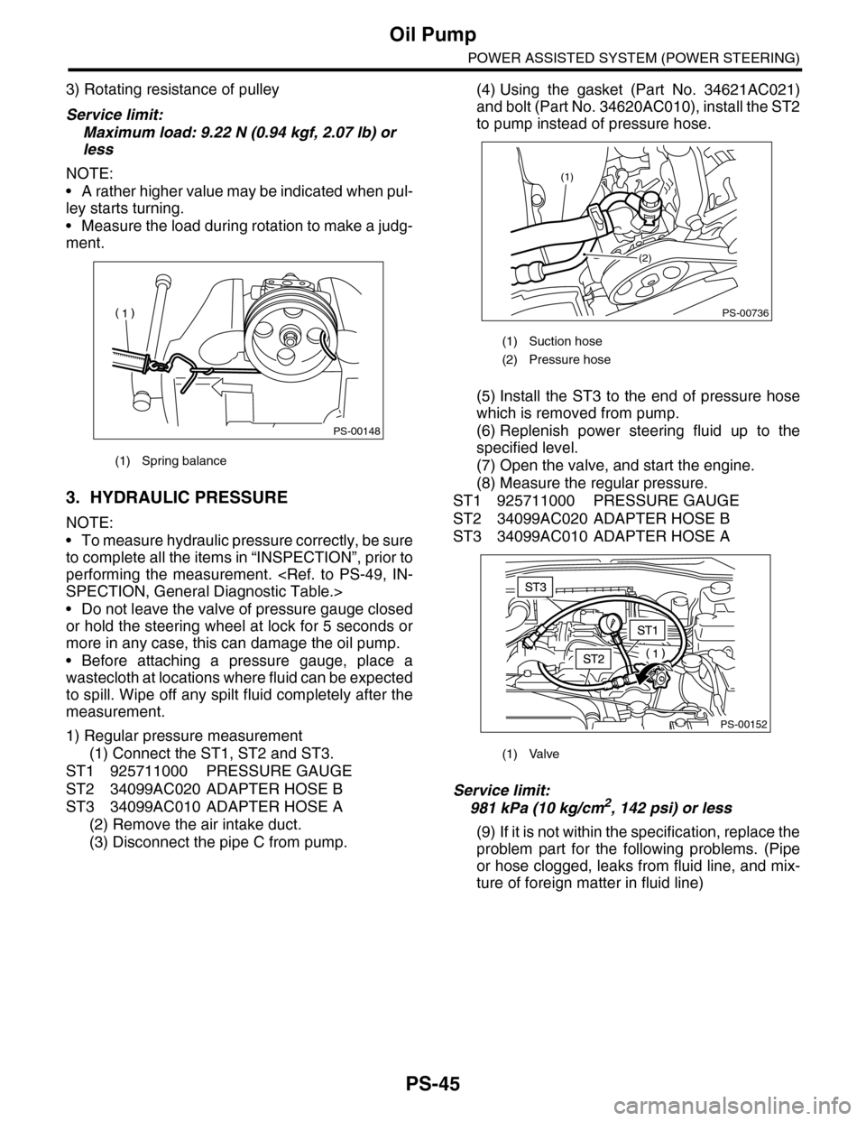
3) Rotating resistance of pulley
Service limit:
Maximum load: 9.22 N (0.94 kgf, 2.07 lb) or
less
NOTE:
•A rather higher value may be indicated when pul-
ley starts turning.
•Measure the load during rotation to make a judg-
ment.
3. HYDRAULIC PRESSURE
NOTE:
•To measure hydraulic pressure correctly, be sure
to complete all the items in “INSPECTION”, prior to
performing the measurement.
•Do not leave the valve of pressure gauge closed
or hold the steering wheel at lock for 5 seconds or
more in any case, this can damage the oil pump.
•Before attaching a pressure gauge, place a
wastecloth at locations where fluid can be expected
to spill. Wipe off any spilt fluid completely after the
measurement.
1) Regular pressure measurement
(1) Connect the ST1, ST2 and ST3.
ST1 925711000 PRESSURE GAUGE
ST2 34099AC020 ADAPTER HOSE B
ST3 34099AC010 ADAPTER HOSE A
(2) Remove the air intake duct.
(3) Disconnect the pipe C from pump.
(4) Using the gasket (Part No. 34621AC021)
and bolt (Part No. 34620AC010), install the ST2
to pump instead of pressure hose.
(5) Install the ST3 to the end of pressure hose
which is removed from pump.
(6) Replenish power steering fluid up to the
specified level.
(7) Open the valve, and start the engine.
(8) Measure the regular pressure.
ST1 925711000 PRESSURE GAUGE
ST2 34099AC020 ADAPTER HOSE B
ST3 34099AC010 ADAPTER HOSE A
Service limit:
981 kPa (10 kg/cm2, 142 psi) or less
(9) If it is not within the specification, replace the
problem part for the following problems. (Pipe
or hose clogged, leaks from fluid line, and mix-
ture of foreign matter in fluid line)
(1) Spring balance
PS-00148
(1) Suction hose
(2) Pressure hose
(1) Valve
PS-00736
(1)
(2)
PS-00152
Page 928 of 2453

PS-48
Power Steering Fluid
POWER ASSISTED SYSTEM (POWER STEERING)
9. Power Steering Fluid
A: SPECIFICATION
B: INSPECTION
1) Check the power steering fluid for deterioration
or contamination. If the fluid is highly deteriorated
or contaminated, drain it and refill with new fluid.
2) Check the joints and units for oil leakage. If any
oil leaks are found, repair or replace the applicable
part.
3) Inspect the fluid level of reservoir tank with vehi-
cle on level surface and engine stopped.
If the level is at “MIN. ” point or below, add fluid to
keep the level in the specified range of the indica-
tor. If at “MAX. ” point or above, drain fluid by using
a syringe or the like.
(1) Check at power steering fluid temperature
20°C (68°F); read the fluid level on the “COLD”
side.
(2) Check at power steering fluid temperature
80°C (176°F); read the fluid level on the “HOT”
side.
C: REPLACEMENT
1) Lift-up the vehicle.
2) Remove the crossmember support.
3) Remove the pipe joint in the center of gearbox,
and connect the vinyl hose to the pipe and joint.
Wipe fluid off while turning the steering wheel.
4) Add the specified fluid to reservoir tank at “MAX”
level.
5) Continue to turn the steering wheel slowly from
lock to lock until the bubbles stop appearing on oil
surface while keeping the fluid at the level in the
Step 4).
6) If the steering wheel is turned in a low fluid level
condition, air will be sucked into the pipe. If sucked,
leave it about half an hour and then do the step 5)
again.
7) Start the engine and let it idle.
8) Continue to turn the steering wheel slowly from
lock to lock again until the bubbles stop appearing
on oil surface while keeping the fluid at the level in
Step 4).
Normally bubbles will stop appearing after turning
the steering wheel from lock to lock three times.
9) In case bubbles do not stop appearing in the
tank, leave it about half an hour and then do the
step 4) all over again.
10) Lower the vehicle, and then idle the engine.
11) Continue to turn the steering wheel from lock to
lock until the bubbles stop appearing and change of
the fluid level is within 3 mm (0.12 in).
12) In case the following happens, leave it about
half an hour and then do step 8) to 11) again.
(1) The fluid level changes over 3 mm (0.12 in).
(2) Bubbles remain on the upper surface of the
fluid.
(3) Grinding noise is generated from oil pump.
13) Check the fluid leakage after turning steering
wheel from lock to lock with engine running.
Recommended power steering fluid Manufacturer
AT F D E X R O N I I I o r e q u i v a l e n t
B.P.
CALTEX
CASTROL
MOBIL
SHELL
TEXACO
PS-00745
HOT MAXHOT MAINCOLD MAXCOLD MAIN
Page 930 of 2453

PS-50
General Diagnostic Table
POWER ASSISTED SYSTEM (POWER STEERING)
1. NOISE & VIBRATION
CAUTION:
Do not keep the relief valve operated over five seconds at any time or inner parts of the oil pump may
be damaged due to rapid increase of fluid temperature.
NOTE:
•A screeching noise may be heard immediately after the engine start in extremely cold conditions. In this
case, if the noise goes off during warm-up there is no abnormal function in the system. This is due to the fluid
characteristics in extremely cold condition.
•The oil pump normally makes a small whining noise due to its mechanism. Even if a noise is heard when
steering wheel is turned at stand still, there is no abnormal function in the system provided that the noise
eliminates when the vehicle is driving.
•When turning the steering wheel with the brake applied when the vehicle is parked, a screeching noise
may be generated by the brake disc and pads. This is not a fault in the steering system.
•There may be a small vibration around the steering devices when turning the steering wheel at standstill,
even though the component parts are operating properly.
Hydraulic systems are likely to generate this kind of vibration as well as working noise and fluid noise be-
cause of combined conditions, i.e., road surface and tire surface, engine speed and turning speed of steering
wheel, fluid temperature and braking condition.
These conditions do not indicate a problem in the system.
Confirm vibration for an AT model, by applying the parking brake on a concrete surface, shifting into the “D”
range, and turning the steering wheel repeatedly from slow to rapid, step by step.
Tr o u b l e P o s s i b l e c a u s e C o r r e c t i v e a c t i o n
Hiss noise (continuous)
While engine is running.
Relief valve emits operating sound when steering wheel is
completely turned in either direction. (Do not keep this
condition over five seconds.)
Normal
Relief valve emits operating sound when steering wheel is
not turned. This means that the relief valve is defective. Replace the oil pump.
Rattling noise (intermittent)
While engine is running.
Interference with adjacent parts
Check the clearance.
Correct if necessary.
Loosened installation of oil pump, oil tank, pump bracket,
gearbox or crossmemberRetighten.
Loose oil pump pulley or other pulley(s) Retighten.
Looseness of linkage, play of steering, improper tightening
(looseness) of suspension joint or steering columnRetighten or replace.
Sound generates from the inside of gearbox or oil pump.Replace faulty parts in the gear-
box or oil pump.
Knocking
When turning steering wheel in
both directions with small angle
repeatedly at engine ON or OFF.
Excessive backlash
Loosened lock nut for adjusting backlashAdjust and retighten.
Insufficient tightening or play in the tie–rod or tie–rod end Retighten or replace.
Grinding noise (continuous)
While engine is running.
Air in vane pump
Inspect and retighten the fluid
line connection.
Refill the fluid and vent air.
Va n e p u m p s e i z i n g R e p l a c e t h e o i l p u m p.
Oil pump pulley bearing seized Replace the oil pump.
Folded hose, flattened pipe Replace.
Squeal, squeak (intermittent or
continuous)
While engine is running.
Improper adjustment of pulley belt
Damaged or over tensioned pulley belt
Unequal length of pulley belts
Adjust or replace.
(Replace two belts as a set.)
Runout or dirty V–groove surface of oil pump pulley Clean or replace.
Page 933 of 2453

PS-53
General Diagnostic Table
POWER ASSISTED SYSTEM (POWER STEERING)
3. INSPECTION OF CLEARANCE
This table lists various clearances that must be correctly adjusted to ensure the normal vehicle driving with-
out interfering noise, or any other faults.
Install locations Minimum allowance mm (in)
(1) Crossmember-to-Hose assembly 10 (0.39)
(2) Front frame side-to-Hose assembly 15 (0.59)
(3) Air bag sensor to cooler pipe assembly 10 (0.39)
(4) Air cleaner case-to-Suction hose 10 (0.39)
(5) VDCH/U to Reservoir tank bracket 10 (0.39)
(6) Air boots to Hose clip15 (0.59)
(7) Air boot-to-Hose assembly15 (0.59)
(8) Protector to Hose assembly10 (0.39)
(9) Intake manifold to Suction hose 10 (0.39)
(10) Intake manifold to hose assembly 10 (0.39)
(11) Air cleaner case to Cooler pipe joint block 5 (0.20)
(12) Chain cover to Cooler pipe joint block 20 (0.79)
(13) Oil pipe to Cooler pipe joint block 20 (0.79)
(14) Suction hose to Hose assembly 10 (0.39)
(15) Air boot to Reservoir tank10 (0.39)
(16) Brake pipe to Reservoir tank10 (0.39)
(17) Harness to Hose assembly10 (0.39)
(18) Relay box to Hose assembly15 (0.59)
(19) Bumper beam to Cooler pipe assembly 10 (0.39)
(20) Radiator bracket to Cooler pipe assembly 10 (0.39)
(21) ATF cooler to Cooler pipe assembly 10 (0.39)
(22) Undercover to cooler pipe assembly 10 (0.39)
(23) Protector to Hose assembly10 (0.39)
(24) Protector to Hose assembly15 (0.59)
(25) Return hose to Hose assembly 10 (0.39)
(26) Air cleaner case to Hose assembly 10 (0.39)
(27) Suction hose to Hose assembly 10 (0.39)
(28) Air cleaner case to Return hose 3 (0.12)
(29) Valve housing to DOJ12 (0.47)
(30) Valve housing to Crossmember 1 (0.04)
(31) Mount to Crossmember There must be no contact.
(32) Feed tube to Crossmember3 (0.12)
(33) Elbow to Crossmember3 (0.12)
(34) Cylinder pipe to Crossmember 3 (0.12)
(35) Feed tube to Exhaust pipe18 (0.71)
(36) Tie-rod end to Brake dust cover 2.5 (0.10)
(37) Coupling rubber to AT level gage 10 (0.39)
(38) Yoke to Brake booster5 (0.20)
Page 936 of 2453

RS-3
General Description
REAR SUSPENSION
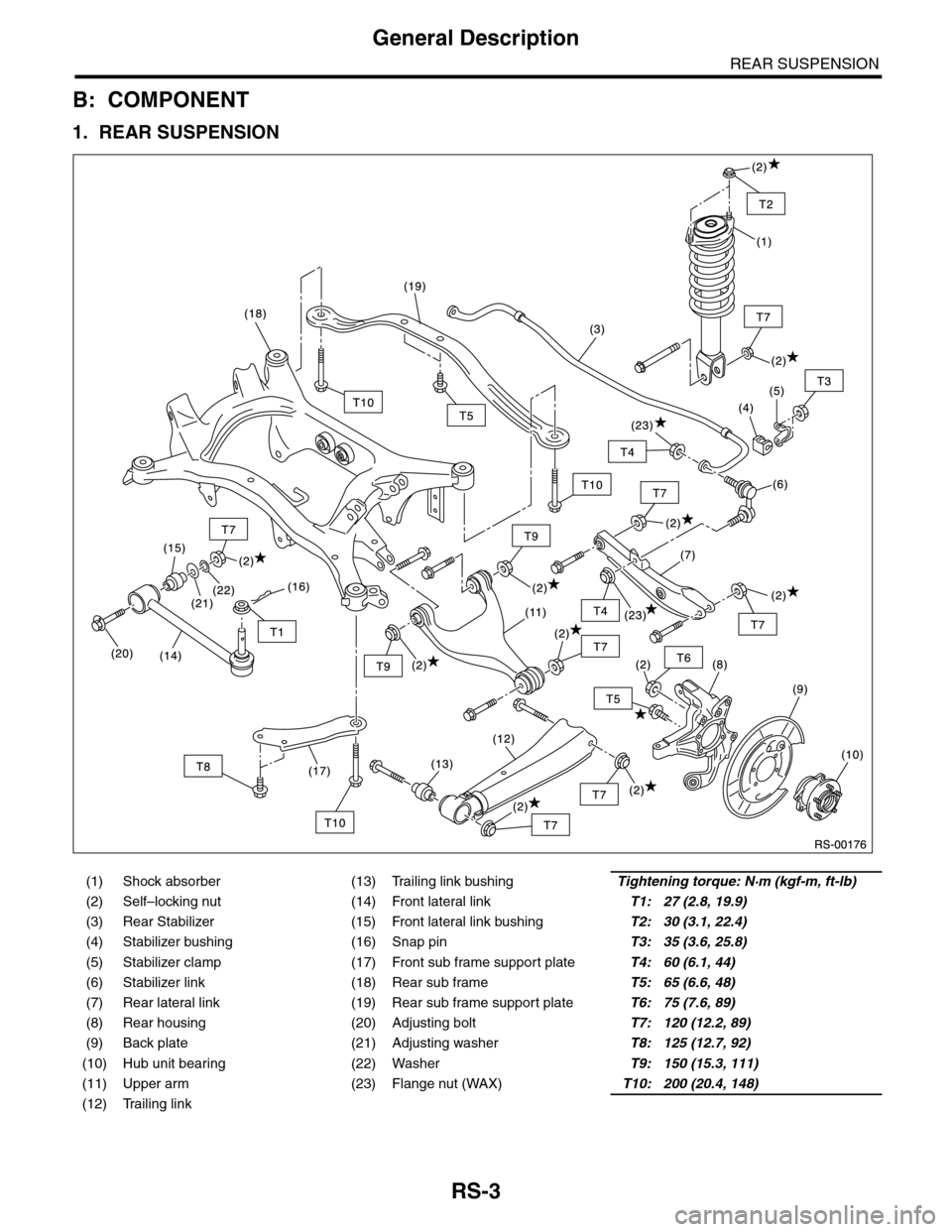
B: COMPONENT
1. REAR SUSPENSION
(1) Shock absorber (13) Trailing link bushingTightening torque: N·m (kgf-m, ft-lb)
(2) Self–locking nut (14) Front lateral linkT1: 27 (2.8, 19.9)
(3) Rear Stabilizer (15) Front lateral link bushingT2: 30 (3.1, 22.4)
(4) Stabilizer bushing (16) Snap pinT3: 35 (3.6, 25.8)
(5) Stabilizer clamp (17) Front sub frame support plateT4: 60 (6.1, 44)
(6) Stabilizer link (18) Rear sub frameT5: 65 (6.6, 48)
(7) Rear lateral link (19) Rear sub frame support plateT6: 75 (7.6, 89)
(8) Rear housing (20) Adjusting boltT7: 120 (12.2, 89)
(9) Back plate (21) Adjusting washerT8: 125 (12.7, 92)
(10) Hub unit bearing (22) WasherT9: 150 (15.3, 111)
(11) Upper arm (23) Flange nut (WAX)T10: 200 (20.4, 148)
(12) Trailing link
Page 937 of 2453

RS-4
General Description
REAR SUSPENSION
2. SHOCK ABSORBER
C: CAUTION
Please understand and adhere to the following general precautions. They must be strictly followed to avoid
any injury to the person performing the work or persons in the area.
1. OPERATION
•Wear work clothing, including a cap, protective goggles and protective shoes during operation.
•Before disposing of shock absorbers, be sure to bleed the gas out completely. Also, do not expose to
flames or fire.
•Before removal, installation or disassembly, be sure to clarify the failure. Avoid unnecessary removal, in-
stallation, disassembly and replacement.
•Use SUBARU genuine grease etc. or equivalent. Do not mix grease etc. with that of another grade or from
other manufacturers.
•Before securing a part on a vise, place cushioning material such as wood blocks, aluminum plate, or cloth
between the part and the vise.
•Be sure to tighten fasteners including bolts and nuts to the specified torque.
•Place shop jacks or rigid racks at the specified points.
2. OIL
When handling oil, follow the rules below to prevent unexpected accidents.
•Prepare container and waste cloths when performing work which oil could possibly spill. If oil spills, wipe
it off immediately to prevent from penetrating into floor or flowing outside, for environmental protection.
•Follow all government regulations concerning disposal of refuse when disposing.
(1) Mount (5) Shock absorberTightening torque: N·m (kgf-m, ft-lb)
(2) Upper rubber sheet (6) Self–locking nutT1: 30 (3.1, 22.4)
(3) Dust cover T2: 35 (3.6, 26)
(4) Coil spring T3: 120 (12.2, 89)
Page 942 of 2453

RS-9
Rear Trailing Link
REAR SUSPENSION
4. Rear Trailing Link
A: REMOVAL
1) Lift-up the vehicle, and then remove the rear
wheels.
2) Remove the bracket, and remove the parking
brake cable from the guide.
3) Remove the ABS wheel speed sensor harness
from the trailing link.
4) Remove the trailing link.
B: INSTALLATION
NOTE:
•Be sure to use a new self-locking nut.
•Always tighten the stabilizer bushing in the state
where the vehicle is at curb weight and the wheels
are in full contact with the ground.
Install in the reverse order of removal.
Tightening torque:
Trailing link
120 N·m (12.2 kgf-m, 89 ft-lb)
Parking Brake Cable bracket
33 N·m (3.4 kgf-m, 24 ft-lb)
C: DISASSEMBLY
Using the ST and a pipe, press the bushing out.
ST 20099PA010 INSTALLER & REMOVER
(1) Guide
RS-00180
(1)
RS-00181
(1) 39 mm dia., 50 mm long pipe
(2) Trailing link
RS-00182
ST
(2)
(1)
Page 944 of 2453

RS-11
Upper Arm
REAR SUSPENSION
5. Upper Arm
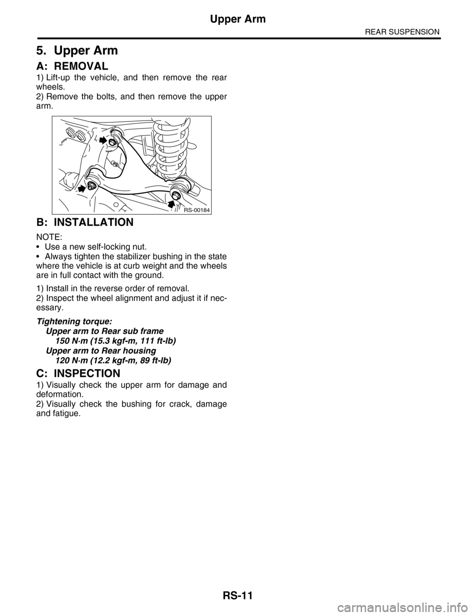
A: REMOVAL
1) Lift-up the vehicle, and then remove the rear
wheels.
2) Remove the bolts, and then remove the upper
arm.
B: INSTALLATION
NOTE:
•Use a new self-locking nut.
•Always tighten the stabilizer bushing in the state
where the vehicle is at curb weight and the wheels
are in full contact with the ground.
1) Install in the reverse order of removal.
2) Inspect the wheel alignment and adjust it if nec-
essary.
Tightening torque:
Upper arm to Rear sub frame
150 N·m (15.3 kgf-m, 111 ft-lb)
Upper arm to Rear housing
120 N·m (12.2 kgf-m, 89 ft-lb)
C: INSPECTION
1) Visually check the upper arm for damage and
deformation.
2) Visually check the bushing for crack, damage
and fatigue.
RS-00184