Page 1407 of 2453
EN(H6DO)(diag)-246
Diagnostic Procedure with Diagnostic Trouble Code (DTC)
ENGINE (DIAGNOSTICS)
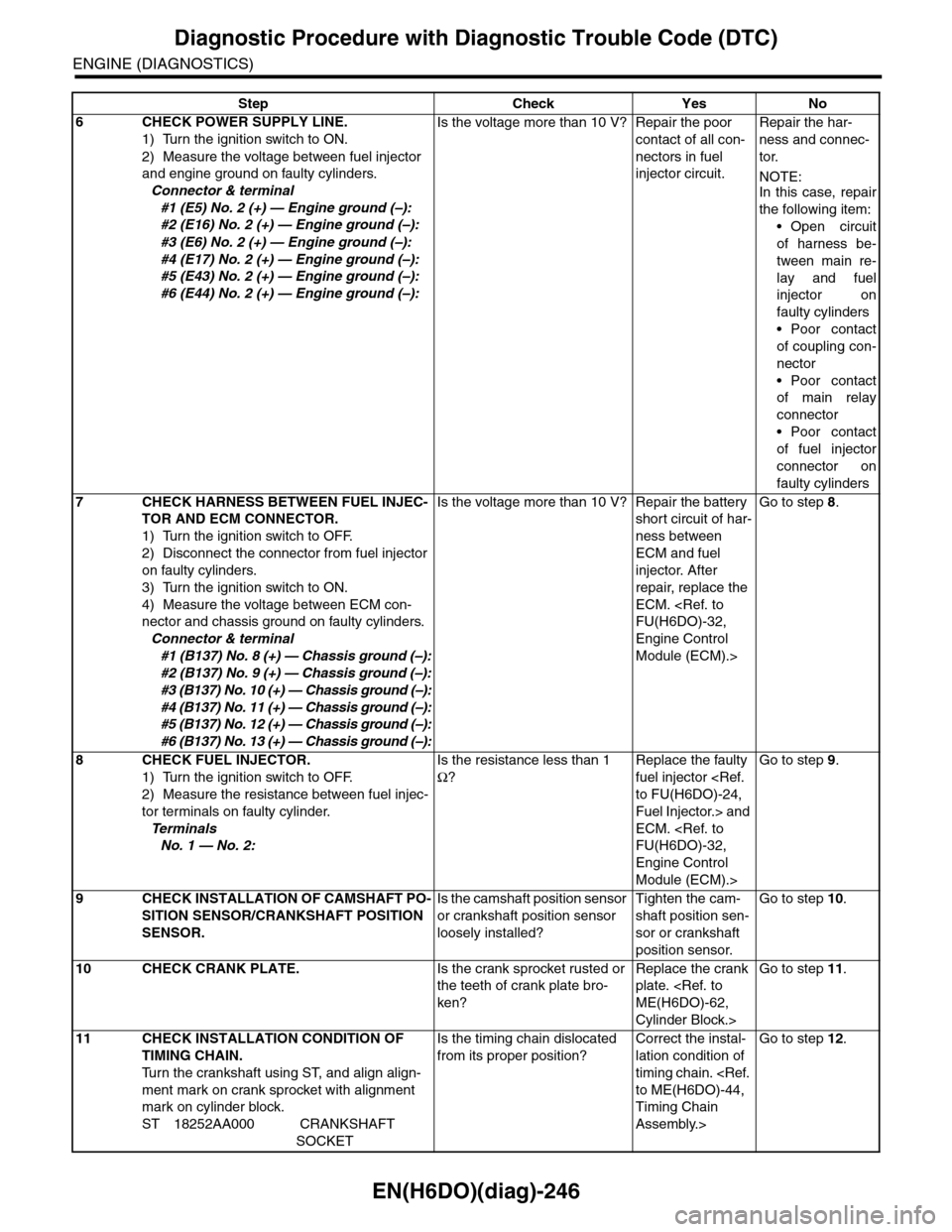
6CHECK POWER SUPPLY LINE.
1) Turn the ignition switch to ON.
2) Measure the voltage between fuel injector
and engine ground on faulty cylinders.
Connector & terminal
#1 (E5) No. 2 (+) — Engine ground (–):
#2 (E16) No. 2 (+) — Engine ground (–):
#3 (E6) No. 2 (+) — Engine ground (–):
#4 (E17) No. 2 (+) — Engine ground (–):
#5 (E43) No. 2 (+) — Engine ground (–):
#6 (E44) No. 2 (+) — Engine ground (–):
Is the voltage more than 10 V? Repair the poor
contact of all con-
nectors in fuel
injector circuit.
Repair the har-
ness and connec-
tor.
NOTE:In this case, repair
the following item:
•Open circuit
of harness be-
tween main re-
lay and fuel
injector on
faulty cylinders
•Poor contact
of coupling con-
nector
•Poor contact
of main relay
connector
•Poor contact
of fuel injector
connector on
faulty cylinders
7CHECK HARNESS BETWEEN FUEL INJEC-
TOR AND ECM CONNECTOR.
1) Turn the ignition switch to OFF.
2) Disconnect the connector from fuel injector
on faulty cylinders.
3) Turn the ignition switch to ON.
4) Measure the voltage between ECM con-
nector and chassis ground on faulty cylinders.
Connector & terminal
#1 (B137) No. 8 (+) — Chassis ground (–):
#2 (B137) No. 9 (+) — Chassis ground (–):
#3 (B137) No. 10 (+) — Chassis ground (–):
#4 (B137) No. 11 (+) — Chassis ground (–):
#5 (B137) No. 12 (+) — Chassis ground (–):
#6 (B137) No. 13 (+) — Chassis ground (–):
Is the voltage more than 10 V? Repair the battery
short circuit of har-
ness between
ECM and fuel
injector. After
repair, replace the
ECM.
FU(H6DO)-32,
Engine Control
Module (ECM).>
Go to step 8.
8CHECK FUEL INJECTOR.
1) Turn the ignition switch to OFF.
2) Measure the resistance between fuel injec-
tor terminals on faulty cylinder.
Te r m i n a l s
No. 1 — No. 2:
Is the resistance less than 1
Ω?
Replace the faulty
fuel injector
to FU(H6DO)-24,
Fuel Injector.> and
ECM.
FU(H6DO)-32,
Engine Control
Module (ECM).>
Go to step 9.
9CHECK INSTALLATION OF CAMSHAFT PO-
SITION SENSOR/CRANKSHAFT POSITION
SENSOR.
Is the camshaft position sensor
or crankshaft position sensor
loosely installed?
Tighten the cam-
shaft position sen-
sor or crankshaft
position sensor.
Go to step 10.
10 CHECK CRANK PLATE.Is the crank sprocket rusted or
the teeth of crank plate bro-
ken?
Replace the crank
plate.
ME(H6DO)-62,
Cylinder Block.>
Go to step 11.
11 CHECK INSTALLATION CONDITION OF
TIMING CHAIN.
Tu r n t h e c r a n k s h a f t u s i n g S T, a n d a l i g n a l i g n -
ment mark on crank sprocket with alignment
mark on cylinder block.
ST 18252AA000 CRANKSHAFT
SOCKET
Is the timing chain dislocated
from its proper position?
Correct the instal-
lation condition of
timing chain.
to ME(H6DO)-44,
Timing Chain
Assembly.>
Go to step 12.
Step Check Yes No
Page 1423 of 2453
EN(H6DO)(diag)-262
Diagnostic Procedure with Diagnostic Trouble Code (DTC)
ENGINE (DIAGNOSTICS)
Step Check Yes No
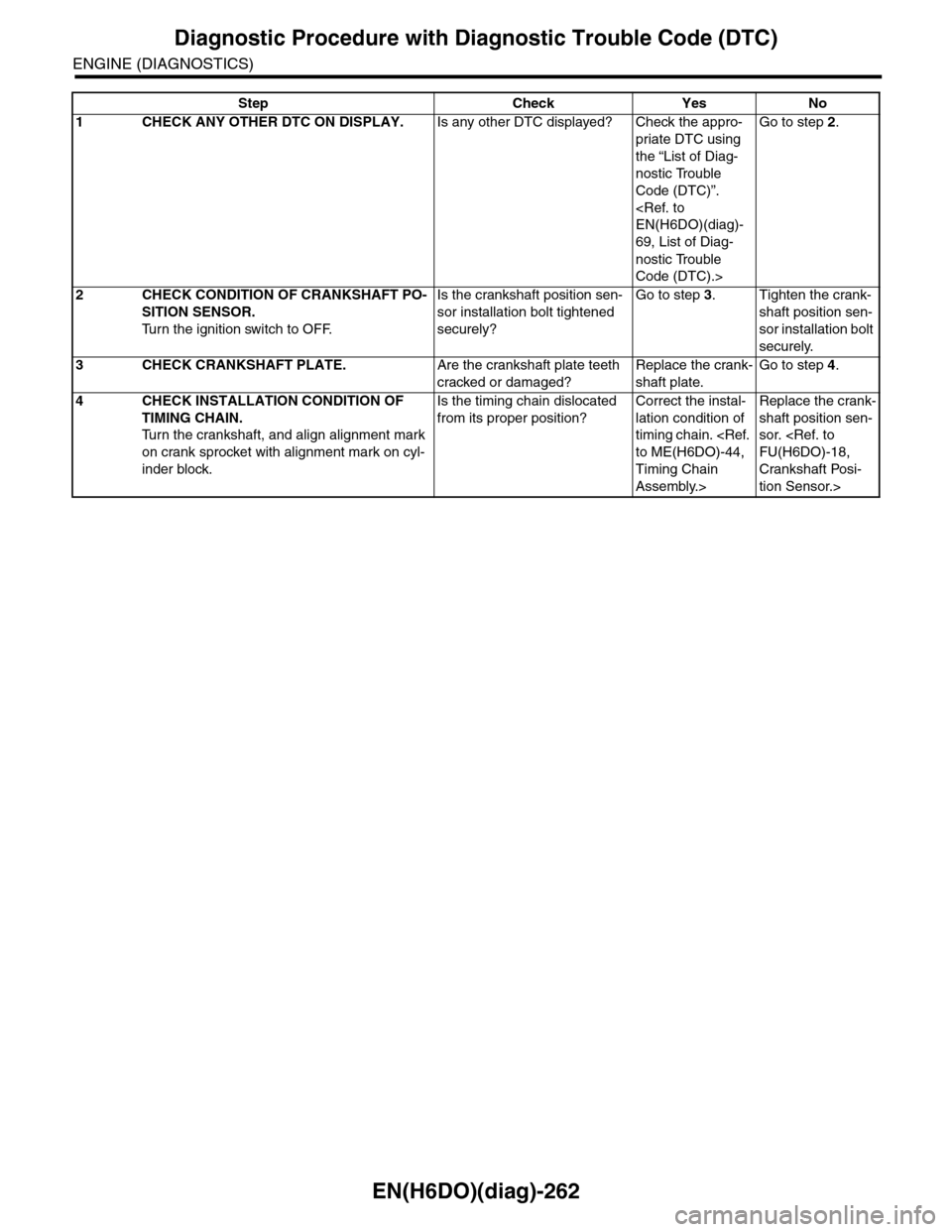
1CHECK ANY OTHER DTC ON DISPLAY.Is any other DTC displayed? Check the appro-
priate DTC using
the “List of Diag-
nostic Trouble
Code (DTC)”.
EN(H6DO)(diag)-
69, List of Diag-
nostic Trouble
Code (DTC).>
Go to step 2.
2CHECK CONDITION OF CRANKSHAFT PO-
SITION SENSOR.
Tu r n t h e i g n i t i o n s w i t c h t o O F F.
Is the crankshaft position sen-
sor installation bolt tightened
securely?
Go to step 3.Tighten the crank-
shaft position sen-
sor installation bolt
securely.
3CHECK CRANKSHAFT PLATE.Are the crankshaft plate teeth
cracked or damaged?
Replace the crank-
shaft plate.
Go to step 4.
4CHECK INSTALLATION CONDITION OF
TIMING CHAIN.
Tu r n t h e c r a n k s h a f t , a n d a l i g n a l i g n m e n t m a r k
on crank sprocket with alignment mark on cyl-
inder block.
Is the timing chain dislocated
from its proper position?
Correct the instal-
lation condition of
timing chain.
to ME(H6DO)-44,
Timing Chain
Assembly.>
Replace the crank-
shaft position sen-
sor.
FU(H6DO)-18,
Crankshaft Posi-
tion Sensor.>
Page 1557 of 2453
EX(H6DO)-3
General Description
EXHAUST
B: CAUTION
•Wear work clothing, including a cap, protective
goggles and protective shoes during operation.
•Remove contamination including dirt and corro-
sion before removal, installation or disassembly.
•Keep the disassembled parts in order and pro-
tect them from dust and dirt.
•Before removal, installation or disassembly, be
sure to clarify the failure. Avoid unnecessary re-
moval, installation, disassembly and replacement.
•Be careful not to burn yourself, because each
part on the vehicle is hot after running.
•Be sure to tighten fasteners including bolts and
nuts to the specified torque.
•Place shop jacks or rigid racks at the specified
points.
•Before disconnecting connectors of sensors or
units, be sure to disconnect the ground cable from
battery.
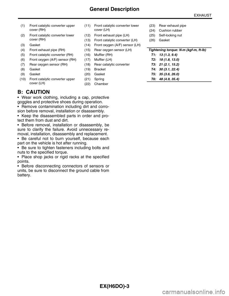
(1) Front catalytic converter upper
cover (RH)
(11) Front catalytic converter lower
cover (LH)
(23) Rear exhaust pipe
(24) Cushion rubber
(2) Front catalytic converter lower
cover (RH)
(12) Front exhaust pipe (LH) (25) Self-locking nut
(13) Front catalytic converter (LH) (26) Gasket
(3) Gasket (14) Front oxygen (A/F) sensor (LH)
(4) Front exhaust pipe (RH) (15) Rear oxygen sensor (LH)Tightening torque: N·m (kgf-m, ft-lb)
(5) Front catalytic converter (RH) (16) Muffler (RH)T1: 13 (1.3, 9.4)
(6) Front oxygen (A/F) sensor (RH) (17) Muffler (LH)T2: 18 (1.8, 13.0)
(7) Rear oxygen sensor (RH) (18) Rear catalytic converterT3: 21 (2.1, 15.2)
(8) Gasket (19) BracketT4: 30 (3.1, 22.4)
(9) Gasket (20) GasketT5: 35 (3.6, 26.0)
(10) Front catalytic converter upper
cover (LH)
(21) SpringT6: 48 (4.9, 35.4)
(22) Chamber
Page 1561 of 2453
EX(H6DO)-7
Rear Exhaust Pipe
EXHAUST
B: INSTALLATION
1) Apply a coat of spray type lubricant to the mating
area of cushion rubber.
2) Install the rear exhaust pipe bracket to cushion
rubber.
3) Install the rear exhaust pipe to muffler.
NOTE:
Use a new gasket and self-locking nut.
Tightening torque:
48 N·m (2.5 kgf-m, 35.4 ft-lb)
•LH side
•RH side
4) Install the rear exhaust pipe to center exhaust
pipe.
Tightening torque:
18 N·m (2.5 kgf-m, 13.0 ft-lb)
C: INSPECTION
1) Check the connections and welds for exhaust
leaks.
2) Make sure there are no holes or rusting.
3) Check the cushion rubber for wear or crack.
EX-00219
EX-00222
EX-02130
EX-02015
Page 1562 of 2453
EX(H6DO)-8
Muffler
EXHAUST
4. Muffler
A: REMOVAL
1) Separate the muffler from rear exhaust pipe.
CAUTION:
Be careful, exhaust pipe is hot.
•LH side
•RH side
2) Apply a coat of spray type lubricant to the mating
area of cushion rubber.
•LH side
•RH side
3) Remove the front and rear cushion rubber, and
then remove the muffler.
B: INSTALLATION
Install in the reverse order of removal.
NOTE:
Use a new gasket and self-locking nut.
Tightening torque:
48 N·m (2.5 kgf-m, 35.4 ft-lb)
•LH side
•RH side
C: INSPECTION
1) Check the connections and welds for exhaust
leaks.
2) Make sure there are no holes or rusting.
3) Check the cushion rubber for wear or crack.
EX-00222
EX-02130
EX-00220
EX-00221
EX-00222
EX-02130
Page 1581 of 2453
FU(H6DO)-20
Knock Sensor
FUEL INJECTION (FUEL SYSTEMS)
7. Knock Sensor
A: REMOVAL
1) Remove the collector cover.
2) Disconnect the ground cable from battery.
3) Remove the intake manifold.
fold.>
4) Disconnect the knock sensor connector.
5) Remove the knock sensor from cylinder block.
B: INSTALLATION
1) Install the knock sensor to cylinder block.
Tightening torque:
25 N·m (2.5 kgf-m, 18 ft-lb)
NOTE:
For the knock sensor installation angle, refer to the
figure below.
2) Connect the knock sensor connector.
3) Install the intake manifold.
13, INSTALLATION, Intake Manifold.>
4) Connect the battery ground cable to the battery.
5) Install the collector cover.
(A) Front side of vehicle
FU-00577
45˚30˚10˚
(A)FU-00578
Page 1860 of 2453
LU(H6DO)-11
Oil Pan and Strainer
LUBRICATION
6. Oil Pan and Strainer
A: REMOVAL
NOTE:
Before removing the oil pan upper, remove the en-
gine from vehicle.
MOVAL, Engine Assembly.>
62, REMOVAL, Cylinder Block.>
1) Set the vehicle on a lift.
2) Lift-up the vehicle.
3) Remove the under cover.
4) Drain the engine oil.
PLACEMENT, Engine Oil.>
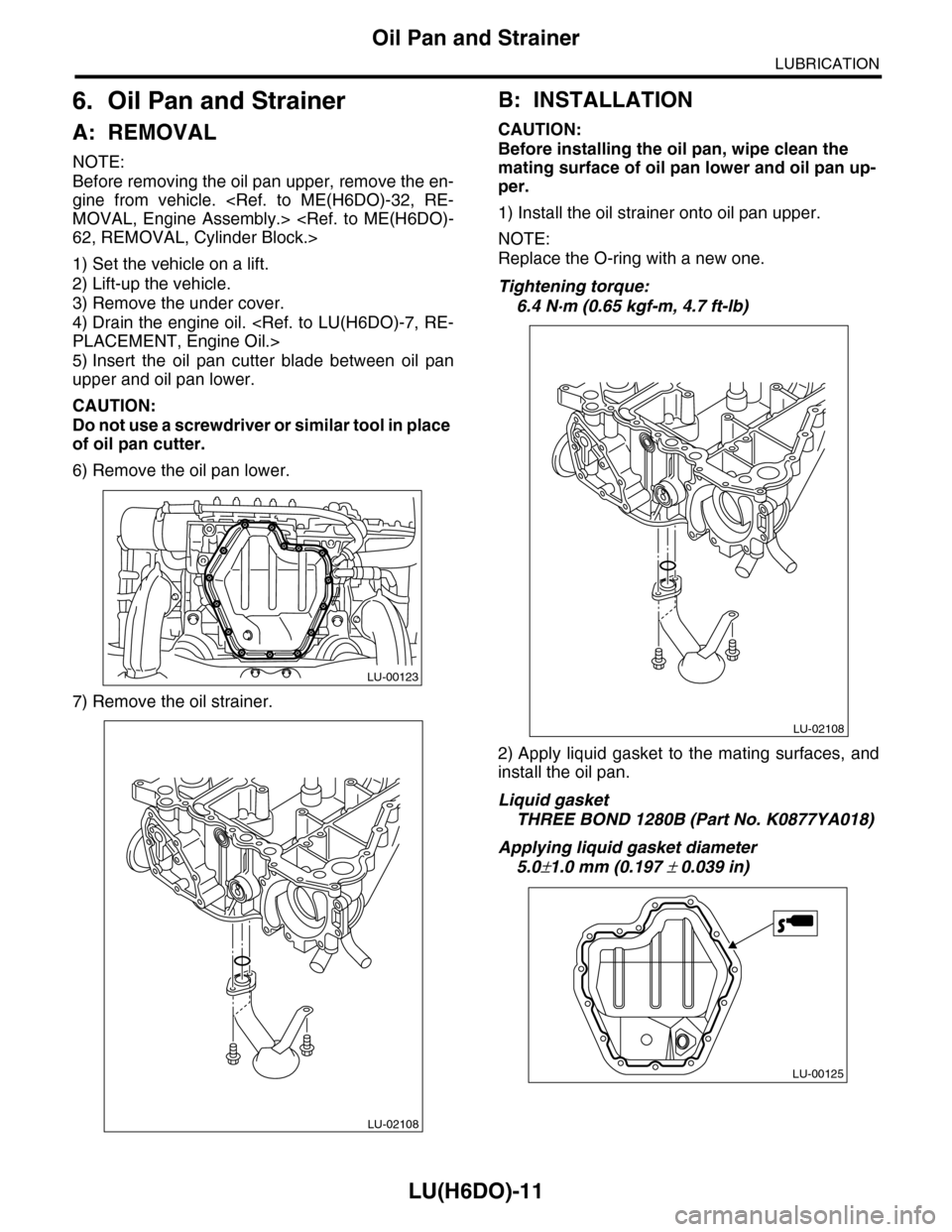
5) Insert the oil pan cutter blade between oil pan
upper and oil pan lower.
CAUTION:
Do not use a screwdriver or similar tool in place
of oil pan cutter.
6) Remove the oil pan lower.
7) Remove the oil strainer.
B: INSTALLATION
CAUTION:
Before installing the oil pan, wipe clean the
mating surface of oil pan lower and oil pan up-
per.
1) Install the oil strainer onto oil pan upper.
NOTE:
Replace the O-ring with a new one.
Tightening torque:
6.4 N·m (0.65 kgf-m, 4.7 ft-lb)
2) Apply liquid gasket to the mating surfaces, and
install the oil pan.
Liquid gasket
THREE BOND 1280B (Part No. K0877YA018)
Applying liquid gasket diameter
5.0±1.0 mm (0.197 ± 0.039 in)
LU-00123
LU-02108
LU-02108
LU-00125
Page 1869 of 2453
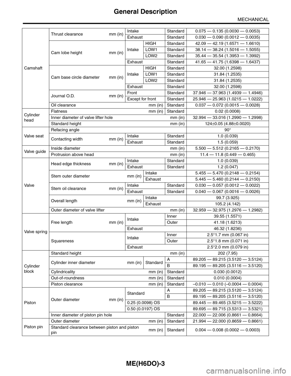
ME(H6DO)-3
General Description
MECHANICAL
Camshaft
Thrust clearance mm (in)Intake Standard 0.075 — 0.135 (0.0030 — 0.0053)
Exhaust Standard 0.030 — 0.090 (0.0012 — 0.0035)
Cam lobe height mm (in)Intake
HIGH Standard 42.09 — 42.19 (1.6571 — 1.6610)
LOW1 Standard 38.14 — 38.24 (1.5016 — 1.5055)
LOW2 Standard 35.44 — 35.54 (1.3953 — 1.3992)
Exhaust Standard 41.65 — 41.75 (1.6398 — 1.6437)
Cam base circle diameter mm (in)Intake
HIGH Standard 32.00 (1.2598)
LOW1 Standard 31.84 (1.2535)
LOW2 Standard 31.84 (1.2535)
Exhaust Standard 32.00 (1.2598)
Journal O.D. mm (in)Fr o nt S ta n da r d 3 7. 9 46 — 3 7 . 96 3 ( 1 . 49 3 9 — 1. 4 9 46 )
Except for front Standard 25.946 — 25.963 (1.0215 — 1.0222)
Oil clearance mm (in) Standard 0.037 — 0.072 (0.0015 — 0.0028)
Cylinder
head
Flatness mm (in) Standard 0.02 (0.0008)
Inner diameter of valve lifter hole mm (in) 32.994 — 33.016 (1.2990 — 1.2998)
Standard height mm (in) 124±0.05 (4.88±0.0020)
Va l ve s e a t
Refacing angle90°
Contacting width mm (in)Intake Standard 1.0 (0.039)
Exhaust Standard 1.5 (0.059)
Va l ve g u i d eInside diameter mm (in) 5.500 — 5.512 (0.2165 — 0.2170)
Protrusion above head mm (in) 11.4 — 11.8 (0.449 — 0.465)
Va l ve
Head edge thickness mm (in)Intake Standard 1.0 (0.039)
Exhaust Standard 1.2 (0.047)
Stem outer diameter mm (in)Intake 5.455 — 5.470 (0.2148 — 0.2154)
Exhaust 5.445 — 5.460 (0.2144 — 0.2150)
Stem oil clearance mm (in)Intake Standard 0.030 — 0.057 (0.0012 — 0.0022)
Exhaust Standard 0.040 — 0.067 (0.0016 — 0.0026)
Overall length mm (in)Intake 99.7 (3.925)
Exhaust 105.2 (4.142)
Outer diameter of valve lifter mm (in) 32.959 — 32.975 (1.2976 — 1.2982)
Va l ve s p r i n g
Free length mm (in)IntakeInner 39.55 (1.5571)
Outer 41.18 (1.6213)
Exhaust 46.32 (1.8236)
SquarenessIntakeInner 2.5°1.7 mm (0.067 in)
Outer 2.5°1.8 mm (0.071 in)
Exhaust 2.5°2.0 mm (0.079 in)
Cylinder
block
Standard height mm (in) 202 (7.95)
Cylinder inner diameter mm (in) StandardA89.205 — 89.215 (3.5120 — 3.5124)
B89.195 — 89.205 (3.5116 — 3.5120)
Cylindricality mm (in) Standard 0.030 (0.0012)
Out-of-roundness mm (in) Standard 0.010 (0.0004)
Piston clearance mm (in) Standard –0.010 — 0.010 (–0.0004 — 0.0004)
PistonOuter diameter mm (in)
StandardA89.205 — 89.215 (3.5120 — 3.5124)
B89.195 — 89.205 (3.5116 — 3.5120)
0.25 (0.0098) OS 89.445 — 89.465 (3.5215 — 3.5222)
0.50 (0.0197) OS 89.695 — 89.715 (3.5313 — 3.5321)
Inner diameter of piston pin hole Standard 22.000 — 22.006 (0.8661 — 0.8664)
Piston pin
Outer diameter mm (in) Standard 21.994 — 22.000 (0.8659 — 0.8661)
Standard clearance between piston and piston
pinmm (in) Standard 0.004 — 0.008 (0.0002 — 0.0003)