Page 1877 of 2453
ME(H6DO)-11
General Description
MECHANICAL
6. CYLINDER BLOCK
(5)
(6)
(7)
(9)
(5)
(8)
(19)
(19)
(10)
(19)
(19)
(21)
(22)
(23)
T1
T2
T2
T2
T1
T2
T2T5
T2
T9
ME-02381
T4
T6
T10
(5)
(1)
(3)
(4)
(5)
(2)
(19)
(19)
(20)
(19)(19)
T1
T1
T8
T3
T5
T8T8
(5)
(18)
(17)
(13)
(14)(13)
(16)
(13)
(14)(13)
(15)
(13)(13)
(11)(12)
(14)
T6T1
T7
T3
T1
Page 1878 of 2453
ME(H6DO)-12
General Description
MECHANICAL
(1) Cylinder block (RH) (13) ClampTightening torque: N·m (kgf-m, ft-lb)
(2) Cylinder block (LH) (14) HoseT1: 6.4 (0.65, 4.7)
(3) Rear oil seal (15) Oil cooler pipeT2: 18 (1.8, 13.3)
(4) Service hole cover (16) Oil coolerT3: 25 (2.5, 18)
(5) O-ring (17) ConnectorT4: 16 (1.6, 12)
(6) Oil pan upper (18) Oil filterT5: 37 (3.8, 27)
(7) Oil pressure switch (19) PlugT6: 44 (4.5, 33)
(8) Oil strainer (20) Crankshaft position sensor holderT7: 54 (5.5, 40)
(9) Magnet (21) Relief valveT8: 70 (7.1, 52)
(10) Oil pan lower (22) Relief valve springT9: 23 (2.3, 17)
(11) Metal gasket (23) PlugT10: 90 (9.2, 67)
(12) Drain plug
Page 1891 of 2453
ME(H6DO)-25
Engine Oil Pressure
MECHANICAL
6. Engine Oil Pressure
A: INSPECTION
1) Remove the oil pressure switch from cylinder
block.
Pressure Switch.>
2) Connect the oil pressure gauge hose to cylinder
block.
3) Connect the ground cable to the battery.
4) Start the engine, and measure the oil pressure.
OIL PRESSURE (at oil temperature of 80°C
(176°F)):
Standard:
135 kPa (1.4 kgf/cm2, 20 psi) or more (at
600 rpm)
500 kPa (5.1 kgf/cm2, 73 psi) or more (at
5,000 rpm)
CAUTION:
•If the oil pressure is out of specification,
check oil pump, oil filter and lubrication line.
Diagnostics Table.>
•If the oil pressure warning light is turned ON
and oil pressure is in specification, replace the
oil pressure switch.
SPECTION, General Diagnostics Table.>
5) After measuring the oil pressure, install the oil
pressure switch.
LATION, Oil Pressure Switch.>
Tightening torque:
25 N·m (2.5 kgf-m, 18 ft-lb)
Page 1893 of 2453

ME(H6DO)-27
Valve Clearance
MECHANICAL
8. Valve Clearance
A: INSPECTION
Inspection and adjustment of valve clearance
should be performed while engine is cold.
1) Set the vehicle on a lift.
2) Remove the collector cover.
3) Disconnect the ground cable from battery.
4) Lift-up the vehicle.
5) Remove the under cover.
6) Lower the vehicle.
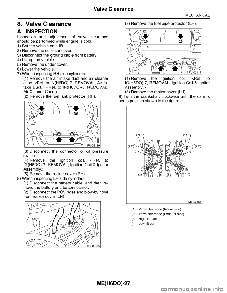
7) When inspecting RH side cylinders:
(1) Remove the air intake duct and air cleaner
case.
take Duct.>
Air Cleaner Case.>
(2) Remove the fuel tank protector (RH).
(3) Disconnect the connector of oil pressure
switch.
(4) Remove the ignition coil.
IG(H6DO)-7, REMOVAL, Ignition Coil & Ignitor
Assembly.>
(5) Remove the rocker cover (RH).
8) When inspecting LH side cylinders:
(1) Disconnect the battery cable, and then re-
move the battery and battery carrier.
(2) Disconnect the PCV hose and blow-by hose
from rocker cover (LH).
(3) Remove the fuel pipe protector (LH).
(4) Remove the ignition coil.
IG(H6DO)-7, REMOVAL, Ignition Coil & Ignitor
Assembly.>
(5) Remove the rocker cover (LH).
9) Turn the crankshaft clockwise until the cam is
set to position shown in the figure.
FU-02119
ME-00460
(1) Valve clearance (Intake side)
(2) Valve clearance (Exhaust side)
(3) High lift cam
(4) Low lift cam
FU-02117
ME-02565
(4)(3)(3)(4)
(1)
(2)
(1)
(2)
(23 )(23 )
Page 1894 of 2453

ME(H6DO)-28
Valve Clearance
MECHANICAL
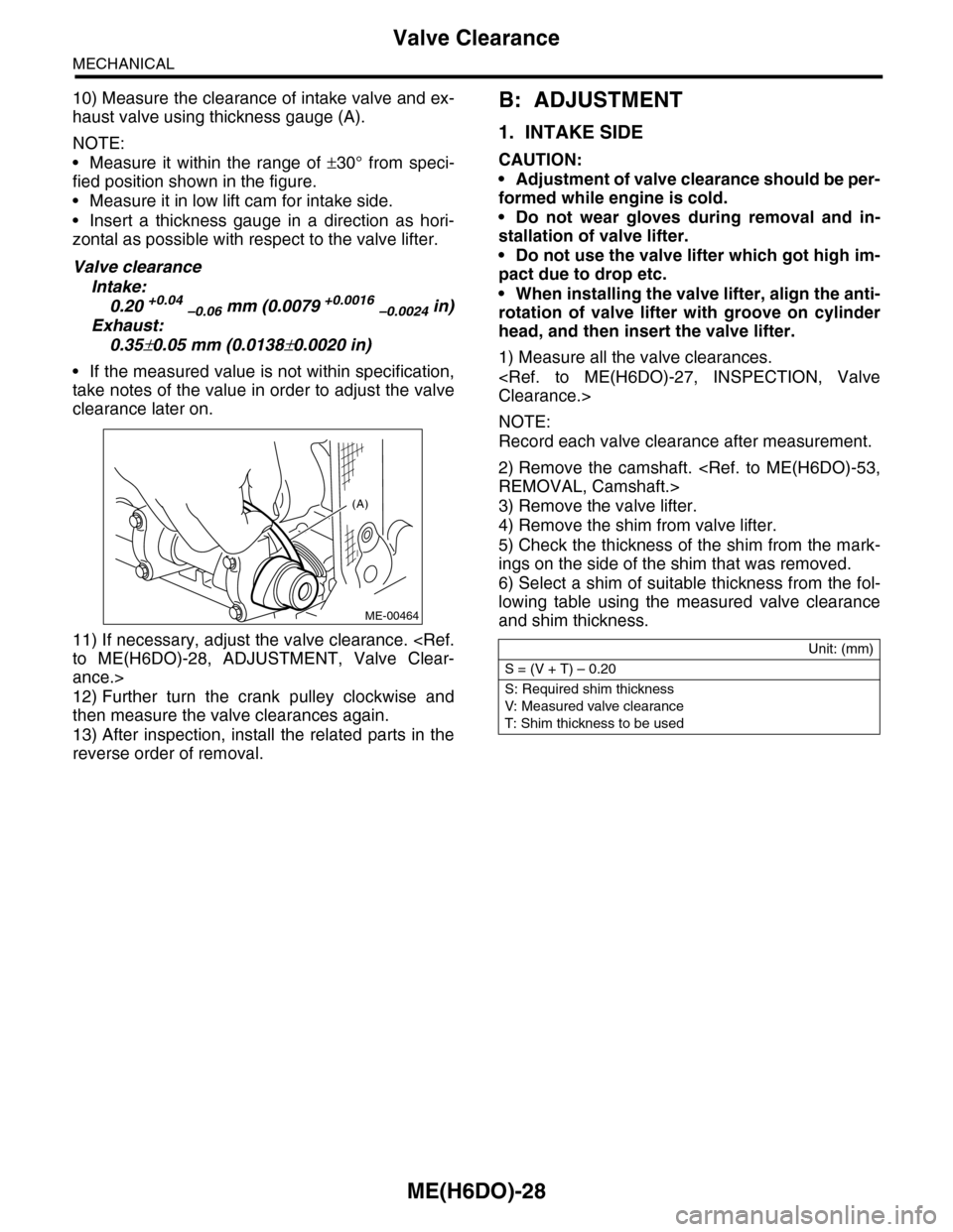
10) Measure the clearance of intake valve and ex-
haust valve using thickness gauge (A).
NOTE:
•Measure it within the range of ±30° from speci-
fied position shown in the figure.
•Measure it in low lift cam for intake side.
•Insert a thickness gauge in a direction as hori-
zontal as possible with respect to the valve lifter.
Valve clearance
Intake:
0.20 +0.04 –0.06 mm (0.0079 +0.0016 –0.0024 in)
Exhaust:
0.35±0.05 mm (0.0138±0.0020 in)
•If the measured value is not within specification,
take notes of the value in order to adjust the valve
clearance later on.
11) If necessary, adjust the valve clearance.
to ME(H6DO)-28, ADJUSTMENT, Valve Clear-
ance.>
12) Further turn the crank pulley clockwise and
then measure the valve clearances again.
13) After inspection, install the related parts in the
reverse order of removal.
B: ADJUSTMENT
1. INTAKE SIDE
CAUTION:
•Adjustment of valve clearance should be per-
formed while engine is cold.
•Do not wear gloves during removal and in-
stallation of valve lifter.
•Do not use the valve lifter which got high im-
pact due to drop etc.
•When installing the valve lifter, align the anti-
rotation of valve lifter with groove on cylinder
head, and then insert the valve lifter.
1) Measure all the valve clearances.
Clearance.>
NOTE:
Record each valve clearance after measurement.
2) Remove the camshaft.
REMOVAL, Camshaft.>
3) Remove the valve lifter.
4) Remove the shim from valve lifter.
5) Check the thickness of the shim from the mark-
ings on the side of the shim that was removed.
6) Select a shim of suitable thickness from the fol-
lowing table using the measured valve clearance
and shim thickness.
(A)
ME-00464
Unit: (mm)
S = (V + T) – 0.20
S: Required shim thickness
V: Measured valve clearance
T: Shim thickness to be used
Page 1897 of 2453
ME(H6DO)-31
V-belt
MECHANICAL
9. V-belt
A: REMOVAL
1) Install the tool to belt tension adjuster assembly
installation bolt.
2) Rotate the tool clockwise and loosen the V-belt
to remove.
3) Remove the V-belt cover.
B: INSTALLATION
Install in the reverse order of removal.
C: INSPECTION
1) Replace the V-belt, if cracks, fraying or wear is
found.
2) Make sure that the V-belt automatic belt tension
indicator (A) is within the range (D).
(1) Power steering oil pump pulley
(2) Belt tension adjuster ASSY
(3) Crank pulley
(4) A/C compressor
(5) Belt idler
(6) Generator
ME-00473
(1)(6)
(4)
(5)(2)
(3)ME-00474
(A) Indicator
(B) Generator
(C) Power steering oil pump pulley
(D) Service limit
(B)
(A)
(D)
(C)
ME-00475
Page 1907 of 2453
ME(H6DO)-41
Crank Pulley
MECHANICAL
13.Crank Pulley
A: REMOVAL
1) Remove the crank pulley cover.
2) Remove the crank pulley bolt. To lock the crank-
shaft, use ST.
ST 499977100 CRANK PULLEY WRENCH
3) Remove the crank pulley.
B: INSTALLATION
1) Install the crank pulley.
2) Install the crank pulley bolt. To lock the crank-
shaft, use ST.
ST 499977100 CRANK PULLEY WRENCH
(1) Clean the crank pulley thread using com-
pressed air.
(2) Apply engine oil to the crank pulley bolt seat
and thread.
(3) Tighten the crank pulley bolts.
Tightening torque:
178 N·m (18.1 kgf-m, 131 ft-lb)
3) Install the crank pulley cover.
NOTE:
Assemble the O-ring to crank pulley cover.
Tightening torque:
6.4 N·m (0.65 kgf-m, 4.7 ft-lb)
C: INSPECTION
1) Check the crank pulley cover for oil and air leak-
age.
2) Check the crank pulley for looseness.
ME-02028
ME-00497
ME-00497
ME-02028
Page 1911 of 2453

ME(H6DO)-45
Timing Chain Assembly
MECHANICAL
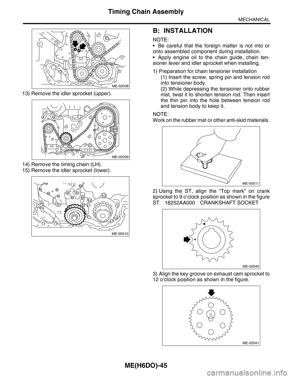
13) Remove the idler sprocket (upper).
14) Remove the timing chain (LH).
15) Remove the idler sprocket (lower).
B: INSTALLATION
NOTE:
•Be careful that the foreign matter is not into or
onto assembled component during installation.
•Apply engine oil to the chain guide, chain ten-
sioner lever and idler sprocket when installing.
1) Preparation for chain tensioner installation
(1) Insert the screw, spring pin and tension rod
into tensioner body.
(2) While depressing the tensioner onto rubber
mat, twist it to shorten tension rod. Then insert
the thin pin into the hole between tension rod
and tension body to keep it.
NOTE:
Work on the rubber mat or other anti-skid materials.
2) Using the ST, align the “Top mark” on crank
sprocket to 9 o’clock position as shown in the figure
ST 18252AA000 CRANKSHAFT SOCKET
3) Align the key groove on exhaust cam sprocket to
12 o’clock position as shown in the figure.
ME-02038
ME-02039
ME-00510
ME-00511
ME-02040
ME-02041