2009 SUBARU TRIBECA lock
[x] Cancel search: lockPage 1975 of 2453
SC(H6DO)-17
Starter
STARTING/CHARGING SYSTEMS
6. SHOCK ABSORBER BEARING CLEAR-
ANCE
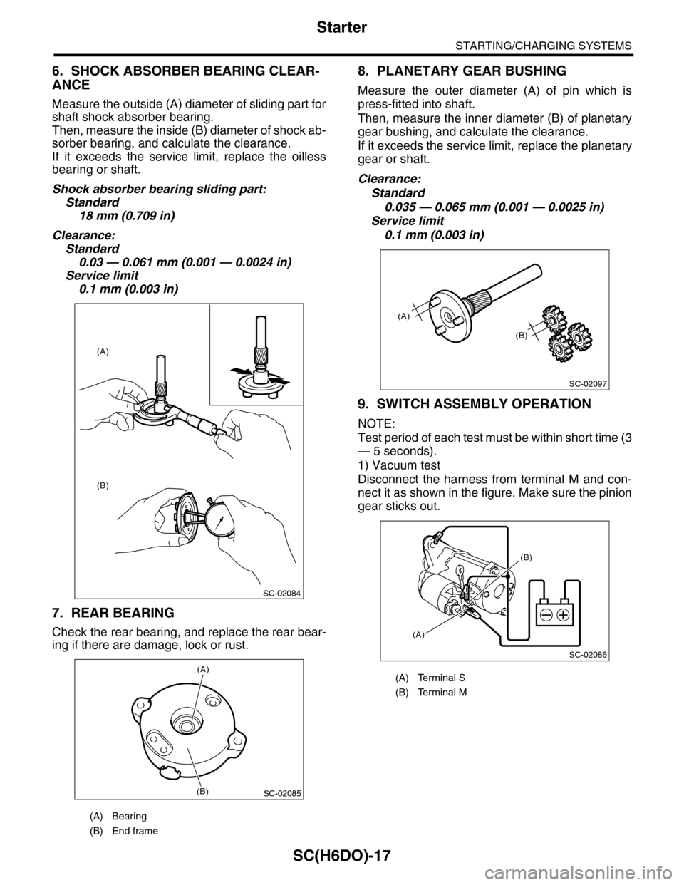
Measure the outside (A) diameter of sliding part for
shaft shock absorber bearing.
Then, measure the inside (B) diameter of shock ab-
sorber bearing, and calculate the clearance.
If it exceeds the service limit, replace the oilless
bearing or shaft.
Shock absorber bearing sliding part:
Standard
18 mm (0.709 in)
Clearance:
Standard
0.03 — 0.061 mm (0.001 — 0.0024 in)
Service limit
0.1 mm (0.003 in)
7. REAR BEARING
Check the rear bearing, and replace the rear bear-
ing if there are damage, lock or rust.
8. PLANETARY GEAR BUSHING
Measure the outer diameter (A) of pin which is
press-fitted into shaft.
Then, measure the inner diameter (B) of planetary
gear bushing, and calculate the clearance.
If it exceeds the service limit, replace the planetary
gear or shaft.
Clearance:
Standard
0.035 — 0.065 mm (0.001 — 0.0025 in)
Service limit
0.1 mm (0.003 in)
9. SWITCH ASSEMBLY OPERATION
NOTE:
Test period of each test must be within short time (3
— 5 seconds).
1) Vacuum test
Disconnect the harness from terminal M and con-
nect it as shown in the figure. Make sure the pinion
gear sticks out.
(A) Bearing
(B) End frame
SC-02084
(A)
(B)
SC-02085
(A)
(B)
(A) Terminal S
(B) Terminal M
SC-02097
(A)
(B)
SC-02086
(A)
(B)
Page 1976 of 2453
SC(H6DO)-18
Starter
STARTING/CHARGING SYSTEMS
2) Hold test
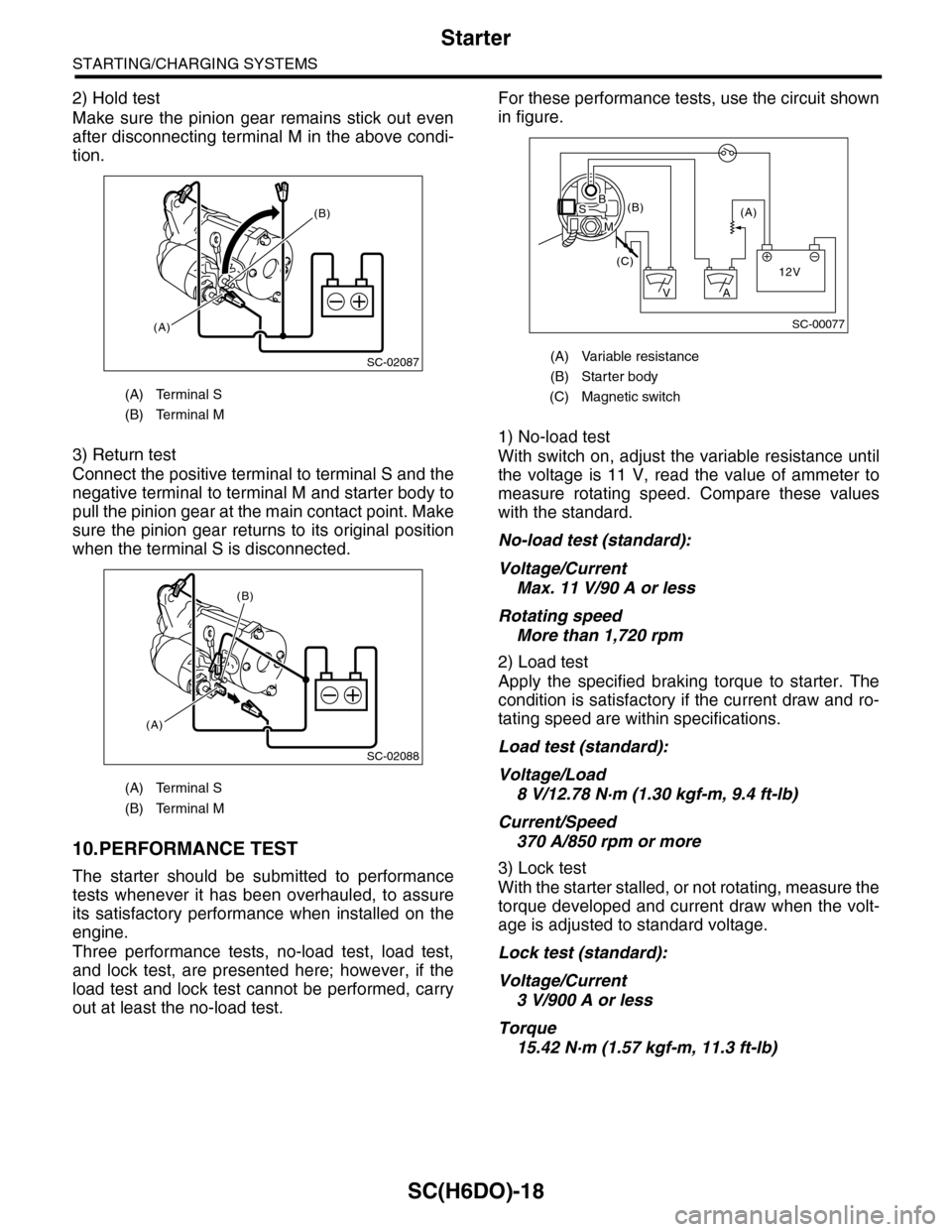
Make sure the pinion gear remains stick out even
after disconnecting terminal M in the above condi-
tion.
3) Return test
Connect the positive terminal to terminal S and the
negative terminal to terminal M and starter body to
pull the pinion gear at the main contact point. Make
sure the pinion gear returns to its original position
when the terminal S is disconnected.
10.PERFORMANCE TEST
The starter should be submitted to performance
tests whenever it has been overhauled, to assure
its satisfactory performance when installed on the
engine.
Three performance tests, no-load test, load test,
and lock test, are presented here; however, if the
load test and lock test cannot be performed, carry
out at least the no-load test.
For these performance tests, use the circuit shown
in figure.
1) No-load test
With switch on, adjust the variable resistance until
the voltage is 11 V, read the value of ammeter to
measure rotating speed. Compare these values
with the standard.
No-load test (standard):
Voltage/Current
Max. 11 V/90 A or less
Rotating speed
More than 1,720 rpm
2) Load test
Apply the specified braking torque to starter. The
condition is satisfactory if the current draw and ro-
tating speed are within specifications.
Load test (standard):
Voltage/Load
8 V/12.78 N·m (1.30 kgf-m, 9.4 ft-lb)
Current/Speed
370 A/850 rpm or more
3) Lock test
With the starter stalled, or not rotating, measure the
torque developed and current draw when the volt-
age is adjusted to standard voltage.
Lock test (standard):
Voltage/Current
3 V/900 A or less
Torque
15.42 N·m (1.57 kgf-m, 11.3 ft-lb)
(A) Terminal S
(B) Terminal M
(A) Terminal S
(B) Terminal M
SC-02087
(B)
(A)
SC-02088
(A)
(B)
(A) Variable resistance
(B) Starter body
(C) Magnetic switch
SC-00077
(A)(B)
(C)12V
+
AV
BS
M
Page 2002 of 2453
PM-19
Brake Line
PERIODIC MAINTENANCE SERVICES
13.Brake Line
A: INSPECTION
1. BRAKE LINE
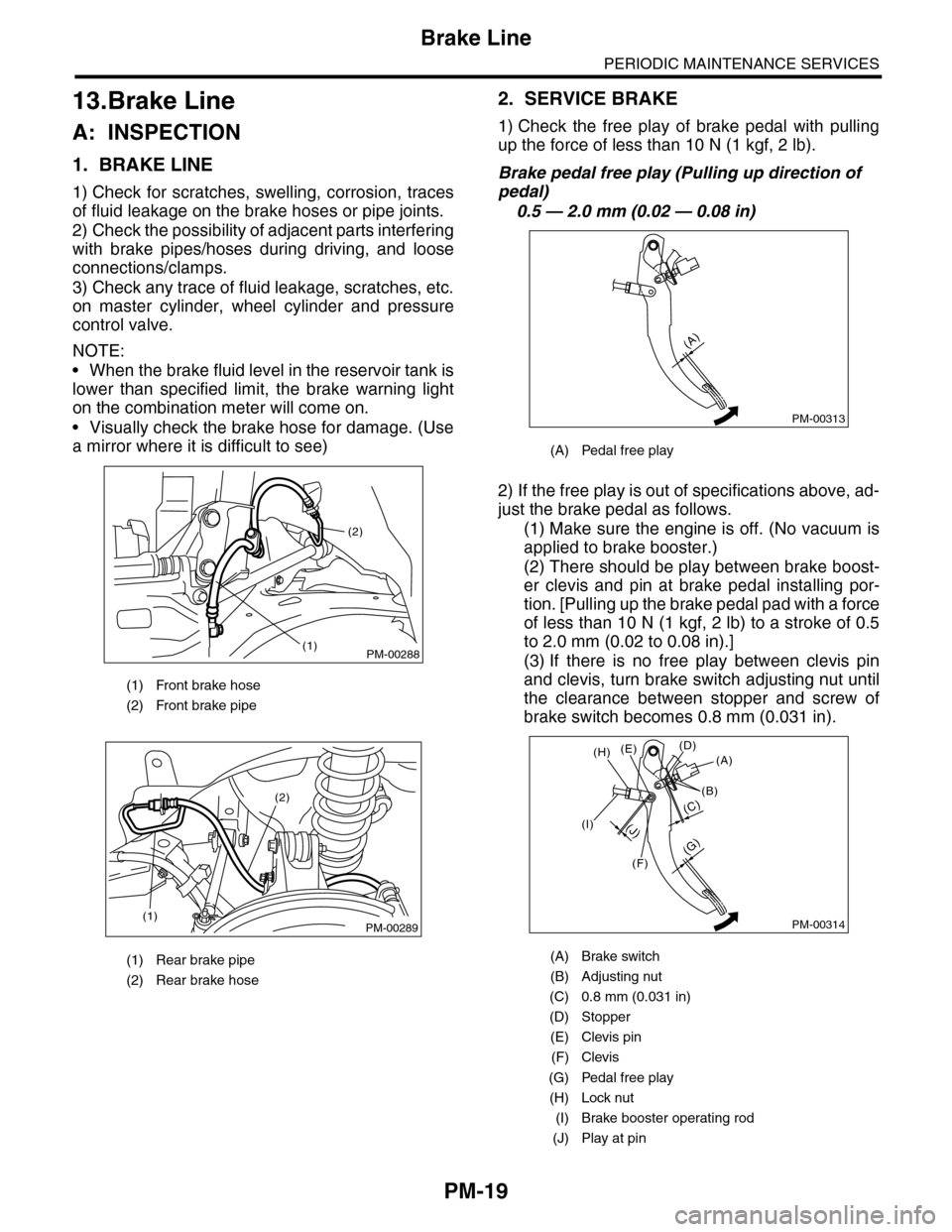
1) Check for scratches, swelling, corrosion, traces
of fluid leakage on the brake hoses or pipe joints.
2) Check the possibility of adjacent parts interfering
with brake pipes/hoses during driving, and loose
connections/clamps.
3) Check any trace of fluid leakage, scratches, etc.
on master cylinder, wheel cylinder and pressure
control valve.
NOTE:
•When the brake fluid level in the reservoir tank is
lower than specified limit, the brake warning light
on the combination meter will come on.
•Visually check the brake hose for damage. (Use
a mirror where it is difficult to see)
2. SERVICE BRAKE
1) Check the free play of brake pedal with pulling
up the force of less than 10 N (1 kgf, 2 lb).
Brake pedal free play (Pulling up direction of
pedal)
0.5 — 2.0 mm (0.02 — 0.08 in)
2) If the free play is out of specifications above, ad-
just the brake pedal as follows.
(1) Make sure the engine is off. (No vacuum is
applied to brake booster.)
(2) There should be play between brake boost-
er clevis and pin at brake pedal installing por-
tion. [Pulling up the brake pedal pad with a force
of less than 10 N (1 kgf, 2 lb) to a stroke of 0.5
to 2.0 mm (0.02 to 0.08 in).]
(3) If there is no free play between clevis pin
and clevis, turn brake switch adjusting nut until
the clearance between stopper and screw of
brake switch becomes 0.8 mm (0.031 in).
(1) Front brake hose
(2) Front brake pipe
(1) Rear brake pipe
(2) Rear brake hose
PM-00288
(2)
(1)
PM-00289(1)
(2)
(A) Pedal free play
(A) Brake switch
(B) Adjusting nut
(C) 0.8 mm (0.031 in)
(D) Stopper
(E) Clevis pin
(F) Clevis
(G) Pedal free play
(H) Lock nut
(I) Brake booster operating rod
(J) Play at pin
PM-00313
(A)
PM-00314
(G)
(A)(D)(E)
(B)
(C)
(F)
(J)(I)
(H)
Page 2006 of 2453
PM-23
Parking Brake
PERIODIC MAINTENANCE SERVICES
16.Parking Brake
A: INSPECTION
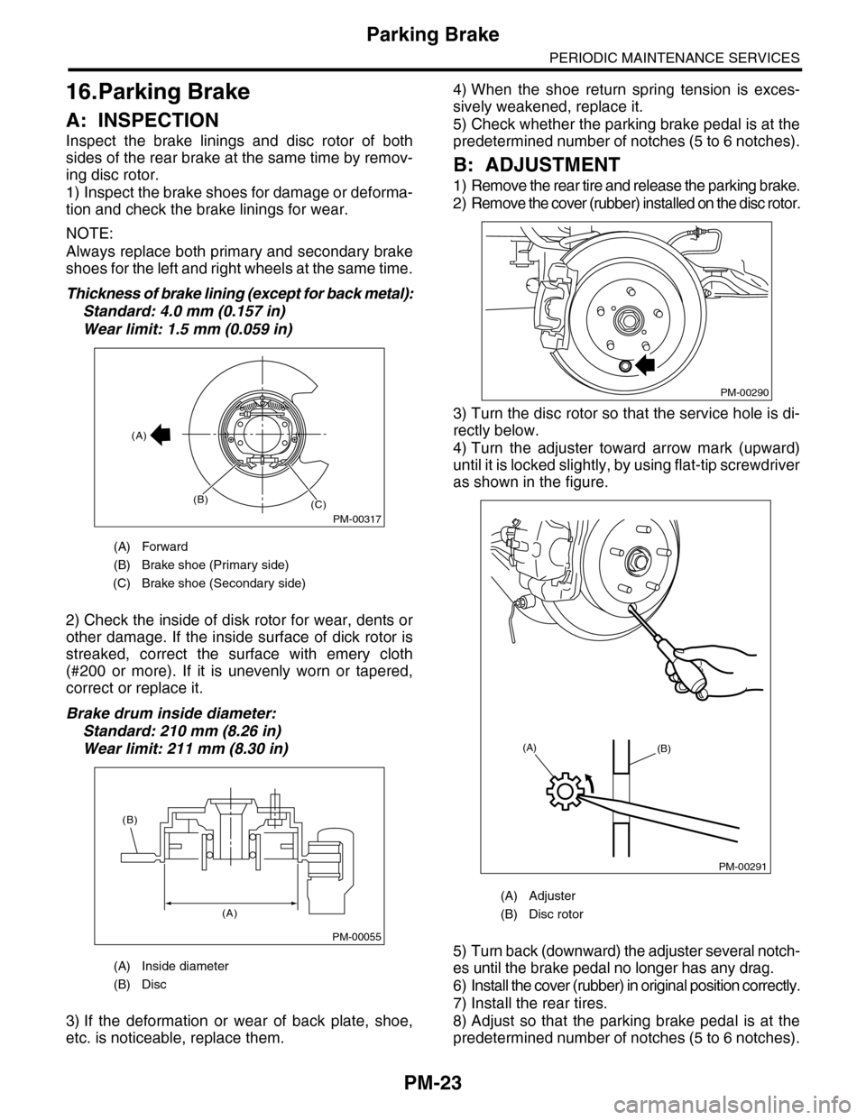
Inspect the brake linings and disc rotor of both
sides of the rear brake at the same time by remov-
ing disc rotor.
1) Inspect the brake shoes for damage or deforma-
tion and check the brake linings for wear.
NOTE:
Always replace both primary and secondary brake
shoes for the left and right wheels at the same time.
Thickness of brake lining (except for back metal):
Standard: 4.0 mm (0.157 in)
Wear limit: 1.5 mm (0.059 in)
2) Check the inside of disk rotor for wear, dents or
other damage. If the inside surface of dick rotor is
streaked, correct the surface with emery cloth
(#200 or more). If it is unevenly worn or tapered,
correct or replace it.
Brake drum inside diameter:
Standard: 210 mm (8.26 in)
Wear limit: 211 mm (8.30 in)
3) If the deformation or wear of back plate, shoe,
etc. is noticeable, replace them.
4) When the shoe return spring tension is exces-
sively weakened, replace it.
5) Check whether the parking brake pedal is at the
predetermined number of notches (5 to 6 notches).
B: ADJUSTMENT
1) Remove the rear tire and release the parking brake.
2) Remove the cover (rubber) installed on the disc rotor.
3) Turn the disc rotor so that the service hole is di-
rectly below.
4) Turn the adjuster toward arrow mark (upward)
until it is locked slightly, by using flat-tip screwdriver
as shown in the figure.
5) Turn back (downward) the adjuster several notch-
es until the brake pedal no longer has any drag.
6) Install the cover (rubber) in original position correctly.
7) Install the rear tires.
8) Adjust so that the parking brake pedal is at the
predetermined number of notches (5 to 6 notches).
(A) Forward
(B) Brake shoe (Primary side)
(C) Brake shoe (Secondary side)
(A) Inside diameter
(B) Disc
PM-00317
(A)
(B)(C)
PM-00055
(A)
(B)
(A) Adjuster
(B) Disc rotor
PM-00290
PM-00291
(A)(B)
Page 2008 of 2453
PM-25
Suspension
PERIODIC MAINTENANCE SERVICES
4. WHEEL ALIGNMENT OF FRONT SUS-
PENSION
1) Check the alignment of front suspension to en-
sure that following items conform to standard val-
ues.
•Toe-in
•Camber
•Caster
•Steering angle
2) When the caster angle does not conform to ref-
erence obviously, visually inspect the following
components and replace deformed parts.
•Suspension components [Strut assembly, cross-
member, front arm, etc.]
•Parts connecting suspension and body
3) When the toe-in and camber are out of standard
value, adjust them so that they conform to standard
value.
4) When the right-and-left turning angles of tire are
out of standard, adjust to standard value.
5. WHEEL ALIGNMENT OF REAR SUS-
PENSION
1) Check the alignment of rear suspension to en-
sure that following items are within standard val-
ues.
•Toe-in
•Camber
•Thrust angle
2) When the camber angle does not conform to
standard value, visually inspect the following com-
ponents. If the deformation is observed, replace the
damaged parts.
•Suspension components [Shock absorber, rear
upper arm, front lateral link, rear lateral link, rear
trailing link, sub frame]
•Parts connecting suspension and body
3) When the toe-in and thrust angle are out of stan-
dard value, adjust them so that they conform to
standard value.
6. OIL LEAKAGE OF STRUT AND SHOCK
ABSORBER
Visually inspect the front strut and rear shock ab-
sorber for oil leakage. Replace the front strut and
rear shock absorber if oil leaks excessively.
7. TIGHTNESS OF BOLTS AND NUTS
Check the bolts and nuts for looseness. Retighten
the bolts and nuts to specified torque. If the self-
locking nuts and bolts are removed, replace them
with new ones.
•Front suspension
•Rear suspension
8. DAMAGE TO SUSPENSION PARTS
Check the following parts and the fastening portion
of the vehicle body for deformation or excessive
rusting which impairs the suspension. If necessary,
replace the damaged parts with new ones. If minor
rust formation, pitting, etc. are noted, remove the
rust and take rust prevention measure.
•Front suspension
•Front arm
•Crossmember
•Strut
•Rear suspension
•Upper arm
•Front lateral link
•Rear lateral link
•Rear trailing link
•Rear sub frame
•Shock absorber
•In the area where salt is sprayed to melt snow on
a road in winter, check suspension parts for dam-
age caused by rust every 12 months after lapse of
60 months. Take rust prevention measures as re-
quired.
Page 2009 of 2453
PM-26
Wheel Bearing
PERIODIC MAINTENANCE SERVICES
18.Wheel Bearing
A: INSPECTION
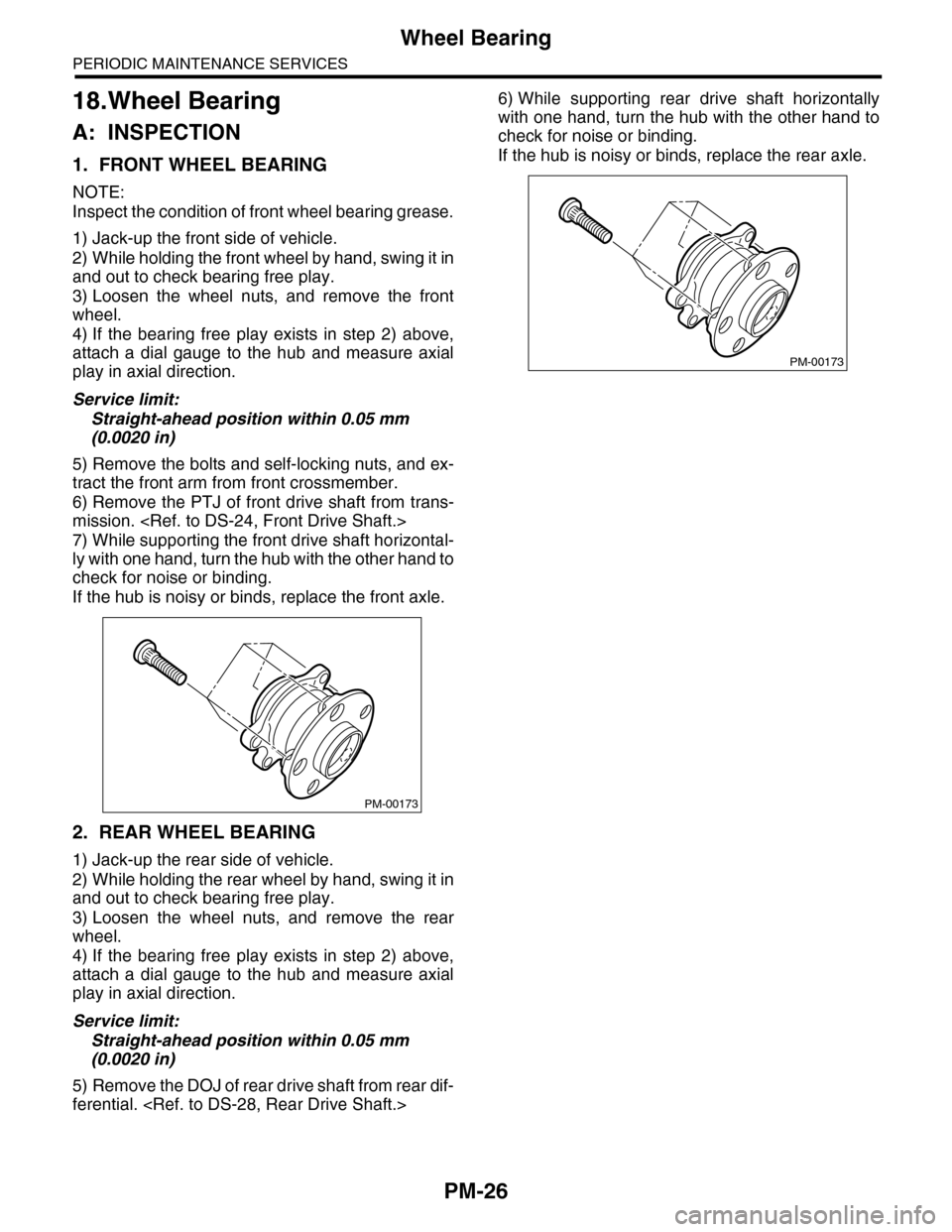
1. FRONT WHEEL BEARING
NOTE:
Inspect the condition of front wheel bearing grease.
1) Jack-up the front side of vehicle.
2) While holding the front wheel by hand, swing it in
and out to check bearing free play.
3) Loosen the wheel nuts, and remove the front
wheel.
4) If the bearing free play exists in step 2) above,
attach a dial gauge to the hub and measure axial
play in axial direction.
Service limit:
Straight-ahead position within 0.05 mm
(0.0020 in)
5) Remove the bolts and self-locking nuts, and ex-
tract the front arm from front crossmember.
6) Remove the PTJ of front drive shaft from trans-
mission.
7) While supporting the front drive shaft horizontal-
ly with one hand, turn the hub with the other hand to
check for noise or binding.
If the hub is noisy or binds, replace the front axle.
2. REAR WHEEL BEARING
1) Jack-up the rear side of vehicle.
2) While holding the rear wheel by hand, swing it in
and out to check bearing free play.
3) Loosen the wheel nuts, and remove the rear
wheel.
4) If the bearing free play exists in step 2) above,
attach a dial gauge to the hub and measure axial
play in axial direction.
Service limit:
Straight-ahead position within 0.05 mm
(0.0020 in)
5) Remove the DOJ of rear drive shaft from rear dif-
ferential.
6) While supporting rear drive shaft horizontally
with one hand, turn the hub with the other hand to
check for noise or binding.
If the hub is noisy or binds, replace the rear axle.
PM-00173
PM-00173
Page 2013 of 2453
PM-30
Steering System (Power Steering)
PERIODIC MAINTENANCE SERVICES
6) Tighten the adjusting screw to 3.9 N·m (0.40 kgf-
m, 2.9 ft-lb) and then loosen 20°.
7) Install the lock nut. While holding the adjusting
screw with wrench, tighten the lock nut using ST.
ST 926230000 SPANNER
Tightening torque (lock nut):
25 N·m (2.5 kgf-m, 18.1 ft-lb)
Hold the adjusting screw with wrench to prevent it
from turning while tightening the lock nut.
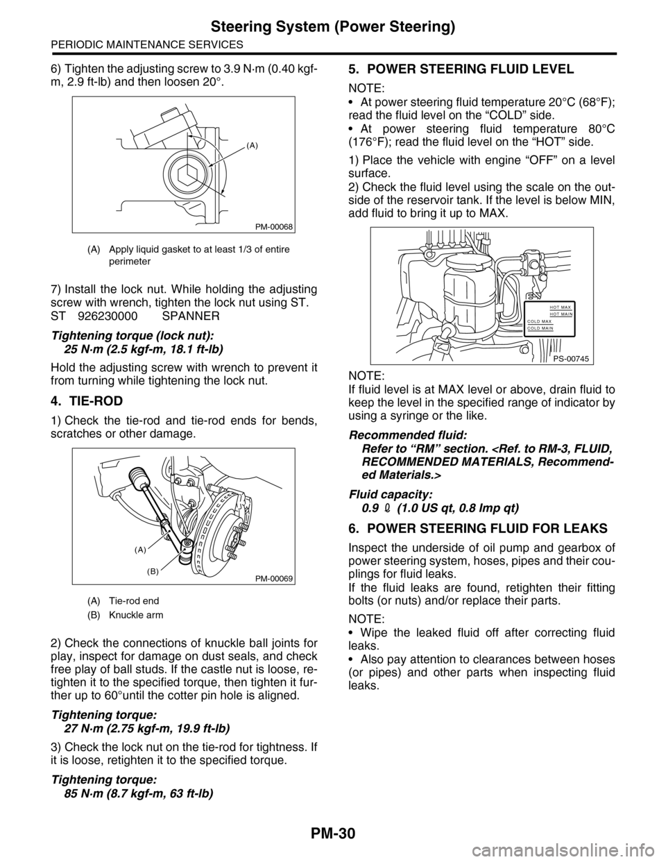
4. TIE-ROD
1) Check the tie-rod and tie-rod ends for bends,
scratches or other damage.
2) Check the connections of knuckle ball joints for
play, inspect for damage on dust seals, and check
free play of ball studs. If the castle nut is loose, re-
tighten it to the specified torque, then tighten it fur-
ther up to 60°until the cotter pin hole is aligned.
Tightening torque:
27 N·m (2.75 kgf-m, 19.9 ft-lb)
3) Check the lock nut on the tie-rod for tightness. If
it is loose, retighten it to the specified torque.
Tightening torque:
85 N·m (8.7 kgf-m, 63 ft-lb)
5. POWER STEERING FLUID LEVEL
NOTE:
•At power steering fluid temperature 20°C (68°F);
read the fluid level on the “COLD” side.
•At power steering fluid temperature 80°C
(176°F); read the fluid level on the “HOT” side.
1) Place the vehicle with engine “OFF” on a level
surface.
2) Check the fluid level using the scale on the out-
side of the reservoir tank. If the level is below MIN,
add fluid to bring it up to MAX.
NOTE:
If fluid level is at MAX level or above, drain fluid to
keep the level in the specified range of indicator by
using a syringe or the like.
Recommended fluid:
Refer to “RM” section.
ed Materials.>
Fluid capacity:
0.9 2 (1.0 US qt, 0.8 Imp qt)
6. POWER STEERING FLUID FOR LEAKS
Inspect the underside of oil pump and gearbox of
power steering system, hoses, pipes and their cou-
plings for fluid leaks.
If the fluid leaks are found, retighten their fitting
bolts (or nuts) and/or replace their parts.
NOTE:
•Wipe the leaked fluid off after correcting fluid
leaks.
•Also pay attention to clearances between hoses
(or pipes) and other parts when inspecting fluid
leaks.
(A) Apply liquid gasket to at least 1/3 of entire
perimeter
(A) Tie-rod end
(B) Knuckle arm
PM-00068
(A)
PM-00069
(A)
(B)
PS-00745
HOT MAXHOT MAINCOLD MAXCOLD MAIN
Page 2020 of 2453
5AT-4
General Description
AUTOMATIC TRANSMISSION
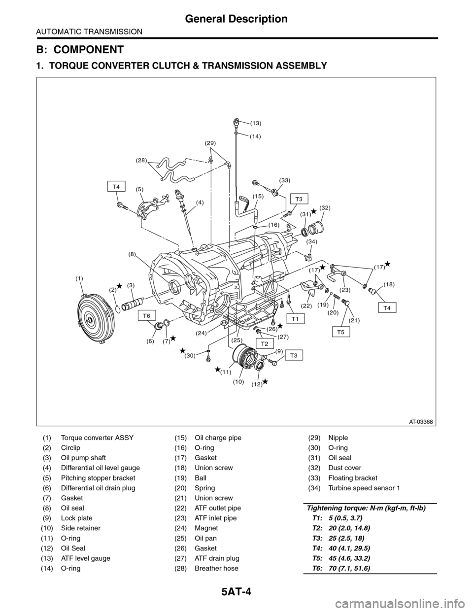
B: COMPONENT
1. TORQUE CONVERTER CLUTCH & TRANSMISSION ASSEMBLY
(1) Torque converter ASSY (15) Oil charge pipe (29) Nipple
(2) Circlip (16) O-ring (30) O-ring
(3) Oil pump shaft (17) Gasket (31) Oil seal
(4) Differential oil level gauge (18) Union screw (32) Dust cover
(5) Pitching stopper bracket (19) Ball (33) Floating bracket
(6) Differential oil drain plug (20) Spring (34) Turbine speed sensor 1
(7) Gasket (21) Union screw
(8) Oil seal (22) ATF outlet pipeTightening torque: N·m (kgf-m, ft-lb)
(9) Lock plate (23) ATF inlet pipeT1: 5 (0.5, 3.7)
(10) Side retainer (24) MagnetT2: 20 (2.0, 14.8)
(11) O-ring (25) Oil panT3: 25 (2.5, 18)
(12) Oil Seal (26) GasketT4: 40 (4.1, 29.5)
(13) ATF level gauge (27) ATF drain plugT5: 45 (4.6, 33.2)
(14) O-ring (28) Breather hoseT6: 70 (7.1, 51.6)
T6
T4
T3
T5
T1
T2
T4
T3
(12)
(11)
(7)(6)
(10)
(21)
(20)
(23)
(26)
(25)(24)(27)
(30)
(19)(22)
(18)
(17)
(34)
(32)
(16)
(15)
(14)
(13)
(28)
(4)
(5)
(1)
(2)(3)
(8)
(29)
(33)
(31)
(9)
(17)
AT-03368