2009 SUBARU TRIBECA lock
[x] Cancel search: lockPage 2102 of 2453

5AT-86
Front Differential Assembly
AUTOMATIC TRANSMISSION
33.Front Differential Assembly
A: REMOVAL
1) Remove the transmission assembly from vehicle
body.
2) Pull out the torque converter assembly.
3) Remove the transmission harness connector
from stay.
4) Remove the oil charge pipe.
5) Remove the ATF filter inlet and outlet pipes.
6) Separate the converter case from the transmis-
sion case.
7) Remove the differential side retainers using ST.
NOTE:
Hold the differential case assembly by hand to
avoid damaging the retainer mounting hole of the
converter case.
ST 18630AA010 WRENCH COMPL RETAIN-
ER
8) Remove the differential assembly while being
careful not to damage the attachment part of retain-
er.
B: INSTALLATION
1) When installing the differential assembly to
case, be careful not to damage the inside of case
(particularly, the differential side retainer mating
surface).
2) Install the O-ring to left and right side retainer.
3) Using the ST, install the side retainer.
ST 18630AA010 WRENCH COMPL RETAIN-
ER
4) Adjust the backlash of the front differential.
sembly.>
5) Install the lock plate.
Tightening torque:
25 N·m (2.5 kgf-m, 18 ft-lb)
6) Install the converter case to the transmission
case.
7) Install the transmission harness connector to the
stay.
8) Install the ATF filter pipe.
9) Install the oil charge pipe together with an O-
ring.
10) Install the torque converter assembly.
sembly.>
11) Install the transmission assembly to the vehi-
cle.
C: DISASSEMBLY
1. DIFFERENTIAL CASE ASSEMBLY
1) Remove the taper roller bearing using the ST
and a press.
ST 498077000 REMOVER
(A) Differential ASSY
AT-01987
(A)
(A) Lock plate
AT-01988
(A)
AT-00216
Page 2106 of 2453
5AT-90
Front Differential Assembly
AUTOMATIC TRANSMISSION
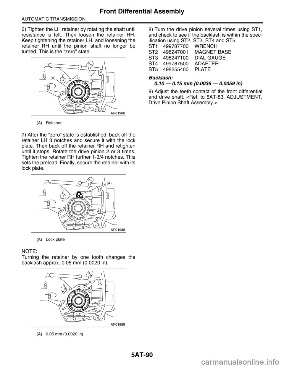
6) Tighten the LH retainer by rotating the shaft until
resistance is felt. Then loosen the retainer RH.
Keep tightening the retainer LH, and loosening the
retainer RH until the pinion shaft no longer be
turned. This is the “zero” state.
7) After the “zero” state is established, back off the
retainer LH 3 notches and secure it with the lock
plate. Then back off the retainer RH and retighten
until it stops. Rotate the drive pinion 2 or 3 times.
Tighten the retainer RH further 1-3/4 notches. This
sets the preload. Finally, secure the retainer with its
lock plate.
NOTE:
Turning the retainer by one tooth changes the
backlash approx. 0.05 mm (0.0020 in).
8) Turn the drive pinion several times using ST1,
and check to see if the backlash is within the spec-
ification using ST2, ST3, ST4 and ST5.
ST1 499787700 WRENCH
ST2 498247001 MAGNET BASE
ST3 498247100 DIAL GAUGE
ST4 499787500 ADAPTER
ST5 498255400 PLATE
Backlash:
0.10 — 0.15 mm (0.0039 — 0.0059 in)
9) Adjust the teeth contact of the front differential
and drive shaft.
(A) Retainer
(A) Lock plate
(A) 0.05 mm (0.0020 in)
AT-01986
(A)
AT-01988
(A)
AT-01989
(A)
Page 2121 of 2453
5AT(diag)-4
Check List for Interview
AUTOMATIC TRANSMISSION (DIAGNOSTICS)
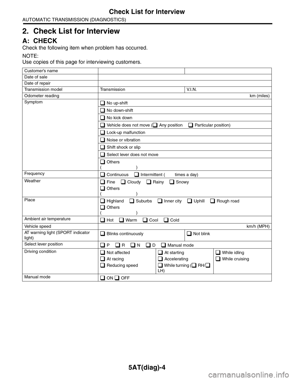
2. Check List for Interview
A: CHECK
Check the following item when problem has occurred.
NOTE:
Use copies of this page for interviewing customers.
Customer’s name
Date of sale
Date of repair
Tr a n s m i s s i o n m o d e l Tr a n s m i s s i o n V. I . N .
Odometer readingkm (miles)
Symptom No up-shift
No down-shift
No kick down
Vehicle does not move ( Any position Particular position)
Lock-up malfunction
Noise or vibration
Shift shock or slip
Select lever does not move
Others
()
Fr e qu e nc y Continuous Intermittent ( times a day)
Weather Fine Cloudy Rainy Snowy
Others
()
Place Highland Suburbs Inner city Uphill Rough road
Others
()
Ambient air temperature Hot Warm Cool Cold
Ve h i c l e s p e e dkm/h (MPH)
AT w a r n i n g l i g h t ( S P O R T i n d i c a t o r
light) Blinks continuously Not blink
Select lever position P R N D Manual mode
Driving condition Not affected
At racing
Reducing speed
At starting
Accelerating
W h i l e t u r n i n g ( R H /
LH)
While idling
While cruising
Manual mode ON OFF
Page 2127 of 2453
5AT(diag)-10
Electrical Component Location
AUTOMATIC TRANSMISSION (DIAGNOSTICS)
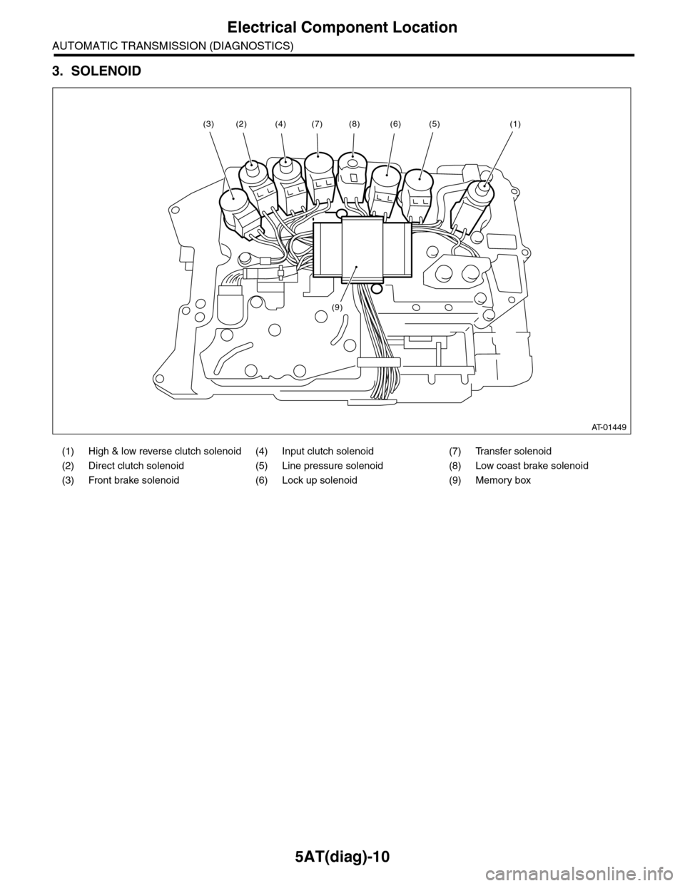
3. SOLENOID
(1) High & low reverse clutch solenoid (4) Input clutch solenoid (7) Transfer solenoid
(2) Direct clutch solenoid (5) Line pressure solenoid (8) Low coast brake solenoid
(3) Front brake solenoid (6) Lock up solenoid (9) Memory box
AT-01449
(8)(6)(5)(1)(7)
(9)
(4)(2)(3)
Page 2129 of 2453
5AT(diag)-12
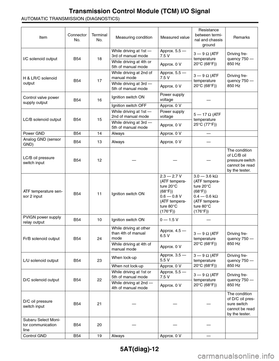
Transmission Control Module (TCM) I/O Signal
AUTOMATIC TRANSMISSION (DIAGNOSTICS)
I/C solenoid output B54 18
While driving at 1st —
3rd of manual mode
Approx. 5.5 —
7.5 V3 — 9 Ω (ATF
temperature
20°C (68°F))
Driving fre-
quency 750 —
850 HzWhile driving at 4th or
5th of manual modeApprox. 0 V
H & LR/C solenoid
outputB54 17
While driving at 2nd of
manual mode
Approx. 5.5 —
7.5 V3 — 9 Ω (ATF
temperature
20°C (68°F))
Driving fre-
quency 750 —
850 HzWhile driving at 3rd —
5th of manual modeApprox. 0 V
Control valve power
supply outputB54 16Ignition switch ONPow er s up p ly
voltage—
Ignition switch OFF Approx. 0 V
LC/B solenoid output B54 15
While driving at 1st —
2nd of manual mode
Pow er s up p ly
voltage5 — 17 Ω (ATF
temperature
25°C (77°F))
While driving at 3rd —
5th of manual modeApprox. 0 V
Pow er GN D B 5 4 1 4 A lways A pp r ox . 0 V —
Analog GND (sensor
GND)B54 13 Always Approx. 0 V —
LC/B oil pressure
switch inputB54 12 — — —
The condition
of LC/B oil
pressure switch
cannot be read
by the tester.
AT F t e m p e r a t u r e s e n -
sor 2 inputB54 11 Ignition switch ON
2.3 — 2.7 V
(ATF tempera-
ture 20°C
(68°F))
0.6 — 0.8 V
(ATF tempera-
ture 80°C
(176°F))
3.0 — 3.6 kΩ
(ATF tempera-
ture 20°C
(68°F))
0.4 — 0.6 kΩ
(ATF tempera-
ture 80°C
(176°F))
PVIGN power supply
relay outputB54 10 Ignition switch ON 0 — 1.5 V —
Fr / B so le n oi d o u tp u t B 5 4 2 4
While driving at other
than 4th of manual
mode
Approx. 4.5 —
6.5 V3 — 9 Ω (ATF
temperature
20°C (68°F))
Driving fre-
quency 750 —
850 HzWhile driving at 4th of
manual modeApprox. 0 V
L/U solenoid output B54 23When lock-upApprox. 3.5 —
5.5 V3 — 9 Ω (ATF
temperature
20°C (68°F))
Driving fre-
quency 750 —
850 HzWhen not lock-up Approx. 0 V
D/C solenoid output B54 22
While driving at 1st or
5th of manual mode
Approx. 5.5 —
7.5 V3 — 9 Ω (ATF
temperature
20°C (68°F))
Driving fre-
quency 750 —
850 HzWhile driving at 2nd —
4th of manual modeApprox. 0 V
D/C oil pressure
switch inputB54 21 — — —
The condition
of D/C oil pres-
sure switch
cannot be read
by the tester.
Subaru Select Moni-
tor communication
line
B54 20 — — —
Control GND B54 19 Always Approx. 0 V —
ItemConnector
No.
Te r m i n a l
No.Measuring condition Measured value
Resistance
between termi-
nal and chassis
ground
Remarks
Page 2130 of 2453
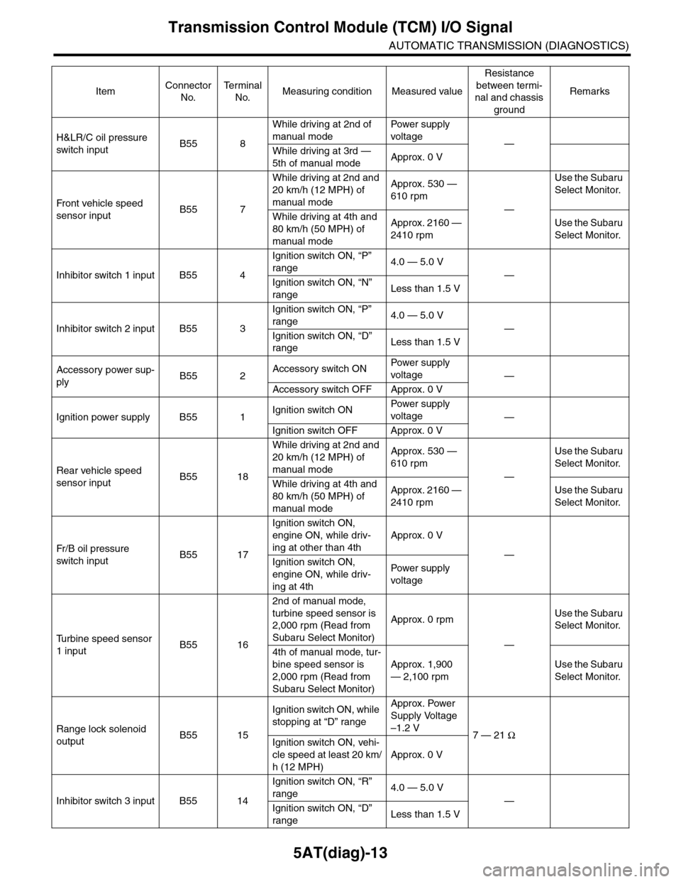
5AT(diag)-13
Transmission Control Module (TCM) I/O Signal
AUTOMATIC TRANSMISSION (DIAGNOSTICS)
H&LR/C oil pressure
switch inputB55 8
While driving at 2nd of
manual mode
Pow er s up p ly
voltage—
While driving at 3rd —
5th of manual modeApprox. 0 V
Fr o nt veh ic l e sp e ed
sensor inputB55 7
While driving at 2nd and
20 km/h (12 MPH) of
manual mode
Approx. 530 —
610 rpm
—
Use the Subaru
Select Monitor.
While driving at 4th and
80 km/h (50 MPH) of
manual mode
Approx. 2160 —
2410 rpm
Use the Subaru
Select Monitor.
Inhibitor switch 1 input B55 4
Ignition switch ON, “P”
range4.0 — 5.0 V
—
Ignition switch ON, “N”
rangeLess than 1.5 V
Inhibitor switch 2 input B55 3
Ignition switch ON, “P”
range4.0 — 5.0 V
—
Ignition switch ON, “D”
rangeLess than 1.5 V
Accessory power sup-
plyB55 2Accessory switch ONPow er s up p ly
voltage—
Accessory switch OFF Approx. 0 V
Ignition power supply B55 1Ignition switch ONPow er s up p ly
voltage—
Ignition switch OFF Approx. 0 V
Rear vehicle speed
sensor inputB55 18
While driving at 2nd and
20 km/h (12 MPH) of
manual mode
Approx. 530 —
610 rpm
—
Use the Subaru
Select Monitor.
While driving at 4th and
80 km/h (50 MPH) of
manual mode
Approx. 2160 —
2410 rpm
Use the Subaru
Select Monitor.
Fr / B oi l p r e ssu r e
switch inputB55 17
Ignition switch ON,
engine ON, while driv-
ing at other than 4th
Approx. 0 V
—
Ignition switch ON,
engine ON, while driv-
ing at 4th
Pow er s up p ly
voltage
Tu r b i n e s p e e d s e n s o r
1 inputB55 16
2nd of manual mode,
turbine speed sensor is
2,000 rpm (Read from
Subaru Select Monitor)
Approx. 0 rpm
—
Use the Subaru
Select Monitor.
4th of manual mode, tur-
bine speed sensor is
2,000 rpm (Read from
Subaru Select Monitor)
Approx. 1,900
— 2,100 rpm
Use the Subaru
Select Monitor.
Range lock solenoid
outputB55 15
Ignition switch ON, while
stopping at “D” range
Approx. Power
Supply Voltage
–1.2 V7 — 21 Ω
Ignition switch ON, vehi-
cle speed at least 20 km/
h (12 MPH)
Approx. 0 V
Inhibitor switch 3 input B55 14
Ignition switch ON, “R”
range4.0 — 5.0 V
—
Ignition switch ON, “D”
rangeLess than 1.5 V
ItemConnector
No.
Te r m i n a l
No.Measuring condition Measured value
Resistance
between termi-
nal and chassis
ground
Remarks
Page 2133 of 2453
5AT(diag)-16
Subaru Select Monitor
AUTOMATIC TRANSMISSION (DIAGNOSTICS)
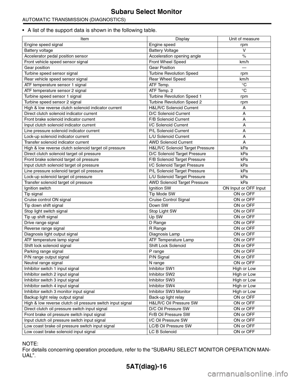
•A list of the support data is shown in the following table.
NOTE:
For details concerning operation procedure, refer to the “SUBARU SELECT MONITOR OPERATION MAN-
UAL”.
Item Display Unit of measure
Engine speed signal Engine speed rpm
Battery voltage Battery Voltage V
Accelerator pedal position sensor Acceleration opening angle %
Fr o nt veh ic l e sp e ed se n so r s ig n al Fr o n t W h ee l S p e ed km/ h
Gear position Gear Position —
Tu r b i n e s p e e d s e n s o r s i g n a l Tu r b i n e R e v o l u t i o n S p e e d r p m
Rear vehicle speed sensor signal Rear Wheel Speed km/h
ATF temperature sensor 1 signal ATF Temp. °C
ATF temperature sensor 2 signal ATF Temp. 2 °C
Tu r b i n e s p e e d s e n s o r 1 s i g n a l Tu r b i n e R e v o l u t i o n S p e e d 1 r p m
Tu r b i n e s p e e d s e n s o r 2 s i g n a l Tu r b i n e R e v o l u t i o n S p e e d 2 r p m
High & low reverse clutch solenoid indicator current H&LR/C Solenoid Current A
Direct clutch solenoid indicator current D/C Solenoid Current A
Fr o nt b rake so l en oi d in di c at o r c u rr e n t F / B S o l en o id Cur r e nt A
Input clutch solenoid indicator current I/C Solenoid Current A
Line pressure solenoid indicator current P/L Solenoid Current A
Lock-up solenoid indicator current L/U Solenoid Current A
Tr a n s f e r s o l e n o i d i n d i c a t o r c u r r e n t A W D S o l e n o i d C u r r e n t A
High & low reverse clutch solenoid target oil pressure H&LR/C Solenoid Target Pressure kPa
Direct clutch solenoid target oil pressure D/C Solenoid Target Pressure kPa
Fr o nt b rake so l en oi d ta r g et o il pr e ss ur e F / B S o l en o id Ta r g et P r es su r e kPa
Input clutch solenoid target oil pressure I/C Solenoid Target Pressure kPa
Line pressure solenoid target oil pressure P/L Solenoid Target Pressure kPa
Lock-up solenoid target oil pressure L/U Solenoid Target Pressure kPa
Tr a n s f e r s o l e n o i d t a r g e t o i l p r e s s u r e A W D S o l e n o i d Ta r g e t P r e s s u r e k P a
Ignition switch Ignition SW ON Input or OFF Input
Tip signal Tip Mode SW ON or OFF
Cruise control ON signal Cruise Control Signal ON or OFF
Tip down shift signal Down SW ON or OFF
Stop light switch signal Stop Light SW ON or OFF
Tip up shift signal Up SW ON or OFF
Drive range signal D Range ON or OFF
Reverse range signal R Range ON or OFF
Diagnosis light output signal Diagnosis Lamp ON or OFF
AT F t e m p e r a t u r e l a m p s i g n a l AT F Te m p e r a t u r e L a m p O N o r O F F
Shift lock solenoid signal Shift Lock Solenoid ON or OFF
Par king range signal P range ON or OFF
P/N range output signal P/N Signal ON or OFF
Neutral range signal N range ON or OFF
Inhibitor switch 1 input signal Inhibitor SW1 High or Low
Inhibitor switch 2 input signal Inhibitor SW2 High or Low
Inhibitor switch 3 input signal Inhibitor SW3 High or Low
Inhibitor switch 4 input signal Inhibitor SW4 High or Low
Inhibitor switch 3 monitor input signal Inhibitor SW3 Monitor High or Low
Backup light relay output signal Back-up light relay ON or OFF
High & low reverse clutch oil pressure switch input signal H&LR/C Oil Pressure SW ON or OFF
Direct clutch oil pressure switch input signal D/C Oil Pressure SW ON or OFF
Fr o nt b rake oi l pr e ss ur e swi tc h i n pu t si gn a l Fr / B Oi l P r e ss ur e S W ON or OF F
Input clutch oil pressure switch input signal I/C Oil Pressure SW ON or OFF
Low coast brake oil pressure switch input signal LC/B Oil Pressure SW ON or OFF
Low coast brake solenoid input signal LC B Solenoid ON or OFF
Page 2145 of 2453
5AT(diag)-28
List of Diagnostic Trouble Code (DTC)
AUTOMATIC TRANSMISSION (DIAGNOSTICS)
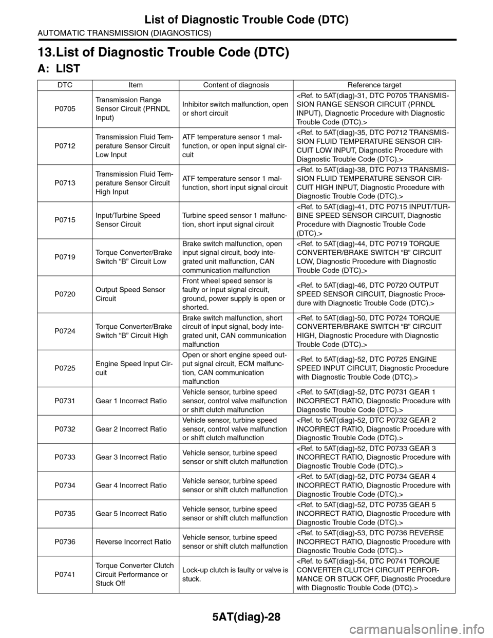
13.List of Diagnostic Trouble Code (DTC)
A: LIST
DTC Item Content of diagnosis Reference target
P0705
Tr a n s m i s s i o n R a n g e
Sensor Circuit (PRNDL
Input)
Inhibitor switch malfunction, open
or short circuit
INPUT), Diagnostic Procedure with Diagnostic
Tr o u b l e C o d e ( D T C ) . >
P0712
Tr a n s m i s s i o n F l u i d Te m -
perature Sensor Circuit
Low Input
AT F t e m p e r a t u r e s e n s o r 1 m a l -
function, or open input signal cir-
cuit
CUIT LOW INPUT, Diagnostic Procedure with
Diagnostic Trouble Code (DTC).>
P0713
Tr a n s m i s s i o n F l u i d Te m -
perature Sensor Circuit
High Input
AT F t e m p e r a t u r e s e n s o r 1 m a l -
function, short input signal circuit
CUIT HIGH INPUT, Diagnostic Procedure with
Diagnostic Trouble Code (DTC).>
P0715Input/Turbine Speed
Sensor Circuit
Tu r b i n e s p e e d s e n s o r 1 m a l f u n c -
tion, short input signal circuit
Procedure with Diagnostic Trouble Code
(DTC).>
P0719To r q u e C o n v e r t e r / B r a k e
Switch “B” Circuit Low
Brake switch malfunction, open
input signal circuit, body inte-
grated unit malfunction, CAN
communication malfunction
LOW, Diagnostic Procedure with Diagnostic
Tr o u b l e C o d e ( D T C ) . >
P0720Output Speed Sensor
Circuit
Front wheel speed sensor is
faulty or input signal circuit,
ground, power supply is open or
shorted.
dure with Diagnostic Trouble Code (DTC).>
P0724To r q u e C o n v e r t e r / B r a k e
Switch “B” Circuit High
Brake switch malfunction, short
circuit of input signal, body inte-
grated unit, CAN communication
malfunction
HIGH, Diagnostic Procedure with Diagnostic
Tr o u b l e C o d e ( D T C ) . >
P0725Engine Speed Input Cir-
cuit
Open or short engine speed out-
put signal circuit, ECM malfunc-
tion, CAN communication
malfunction
with Diagnostic Trouble Code (DTC).>
P0731 Gear 1 Incorrect Ratio
Ve h i c l e s e n s o r, t u r b i n e s p e e d
sensor, control valve malfunction
or shift clutch malfunction
Diagnostic Trouble Code (DTC).>
P0732 Gear 2 Incorrect Ratio
Ve h i c l e s e n s o r, t u r b i n e s p e e d
sensor, control valve malfunction
or shift clutch malfunction
Diagnostic Trouble Code (DTC).>
P0733 Gear 3 Incorrect RatioVe h i c l e s e n s o r, t u r b i n e s p e e d
sensor or shift clutch malfunction
Diagnostic Trouble Code (DTC).>
P0734 Gear 4 Incorrect RatioVe h i c l e s e n s o r, t u r b i n e s p e e d
sensor or shift clutch malfunction
Diagnostic Trouble Code (DTC).>
P0735 Gear 5 Incorrect RatioVe h i c l e s e n s o r, t u r b i n e s p e e d
sensor or shift clutch malfunction
Diagnostic Trouble Code (DTC).>
P0736 Reverse Incorrect RatioVe h i c l e s e n s o r, t u r b i n e s p e e d
sensor or shift clutch malfunction
Diagnostic Trouble Code (DTC).>
P0741
To r q u e C o n v e r t e r C l u t c h
Circuit Performance or
Stuck Off
Lock-up clutch is faulty or valve is
stuck.
MANCE OR STUCK OFF, Diagnostic Procedure
with Diagnostic Trouble Code (DTC).>