Page 2028 of 2453

5AT-12
General Description
AUTOMATIC TRANSMISSION
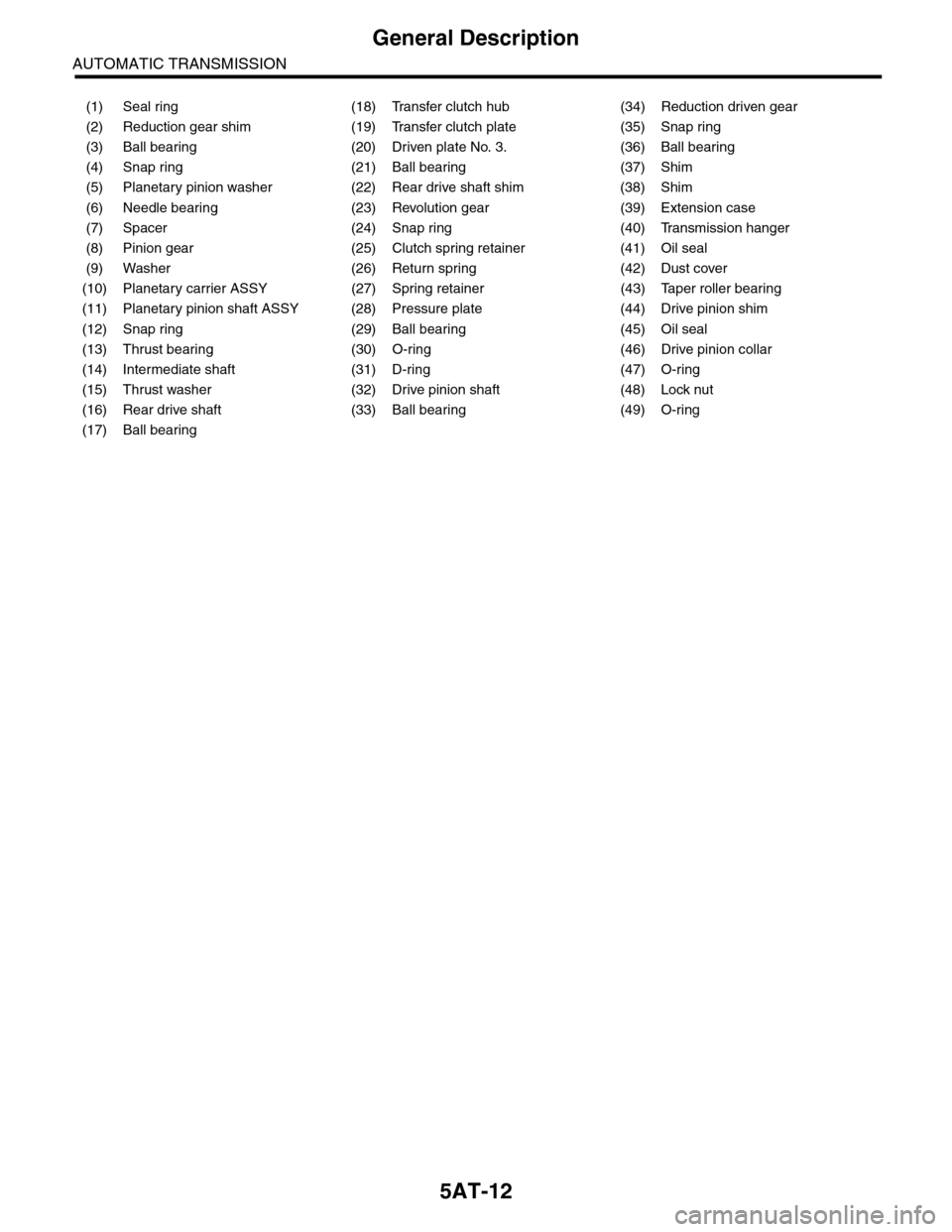
(1) Seal ring (18) Transfer clutch hub (34) Reduction driven gear
(2) Reduction gear shim (19) Transfer clutch plate (35) Snap ring
(3) Ball bearing (20) Driven plate No. 3. (36) Ball bearing
(4) Snap ring (21) Ball bearing (37) Shim
(5) Planetary pinion washer (22) Rear drive shaft shim (38) Shim
(6) Needle bearing (23) Revolution gear (39) Extension case
(7) Spacer (24) Snap ring (40) Transmission hanger
(8) Pinion gear (25) Clutch spring retainer (41) Oil seal
(9) Washer (26) Return spring (42) Dust cover
(10) Planetary carrier ASSY (27) Spring retainer (43) Taper roller bearing
(11) Planetary pinion shaft ASSY (28) Pressure plate (44) Drive pinion shim
(12) Snap ring (29) Ball bearing (45) Oil seal
(13) Thrust bearing (30) O-ring (46) Drive pinion collar
(14) Intermediate shaft (31) D-ring (47) O-ring
(15) Thrust washer (32) Drive pinion shaft (48) Lock nut
(16) Rear drive shaft (33) Ball bearing (49) O-ring
(17) Ball bearing
Page 2033 of 2453

5AT-17
General Description
AUTOMATIC TRANSMISSION
C: CAUTION
•Wear work clothing, including a cap, protective goggles and protective shoes during operation.
•Remove contamination including dirt and corrosion before removal, installation or disassembly.
•Keep the disassembled parts in order and protect them from dust and dirt.
•Until the oil pan is removed, do not place with the oil pan side facing up to prevent foreign matter from en-
tering the valve body.
•Before removal, installation or disassembly, be sure to clarify the failure. Avoid unnecessary removal, dis-
assembly and replacement.
•When disassembling the case and other light alloy parts, disassemble them by slightly tapping with a plas-
tic hammer. Do not pry apart with screwdrivers or other tools.
•Be careful not to burn yourself, because each part on the vehicle is hot after running.
•Use SUBARU genuine gear oil, grease or the equivalent. Do not mix them with that of another grade or
from other manufacturers.
•Be sure to tighten bolts and nuts to the specified torque.
•Place shop jacks or rigid racks at the specified points.
•Apply gear oil onto sliding or revolution surfaces before installation.
•Replace deformed or damaged snap rings with new parts.
•Before installing O-rings or oil seals, apply sufficient amount of ATF fluid to avoid damage and deforma-
tion.
•Be careful not to incorrectly install or fail to install O-rings, snap rings and other such parts.
•Before securing a part on a vise, place cushioning material such as wood blocks, aluminum plate, or cloth
between the part and the vise.
•Avoid damaging the mating surface of the case.
•Before applying liquid gasket, completely remove the old seal.
D: PREPARATION TOOL
1. SPECIAL TOOL
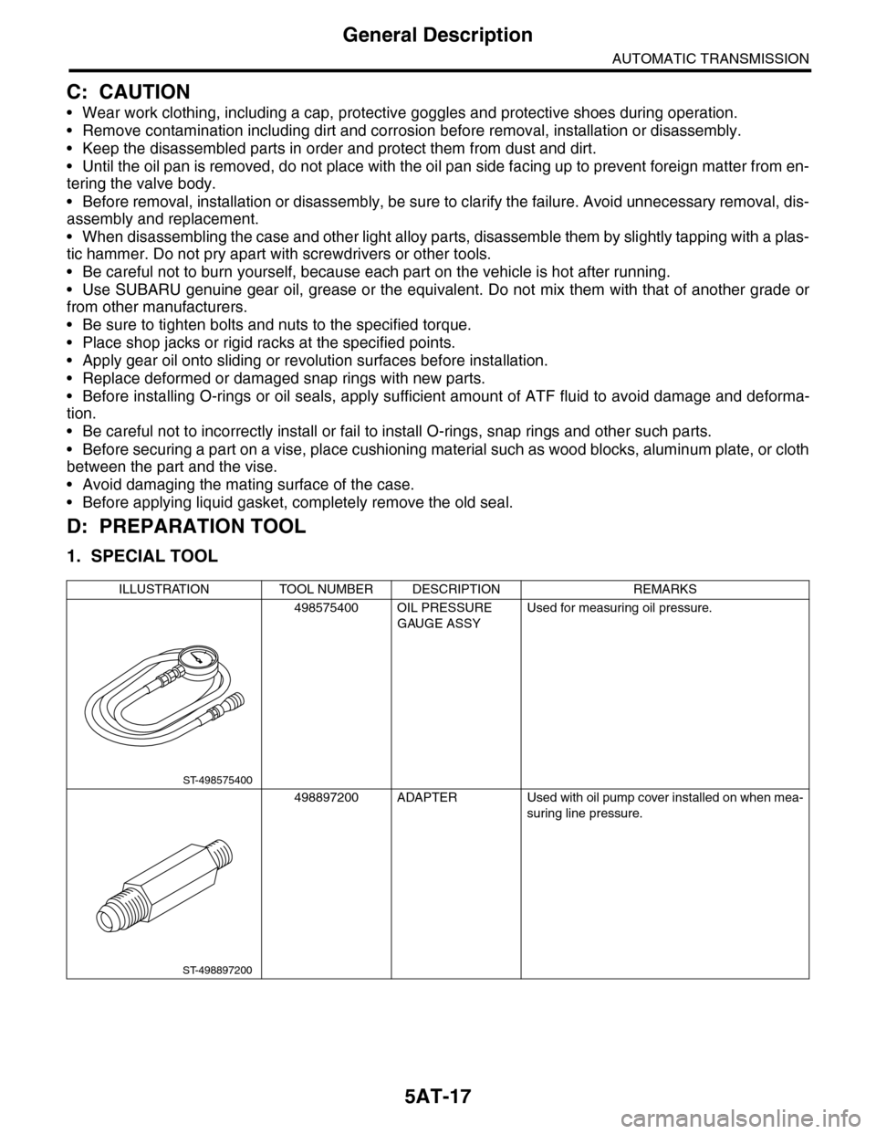
ILLUSTRATION TOOL NUMBER DESCRIPTION REMARKS
498575400 OIL PRESSURE
GAUGE ASSY
Used for measuring oil pressure.
498897200 ADAPTER Used with oil pump cover installed on when mea-
suring line pressure.
ST-498575400
ST-498897200
Page 2036 of 2453
5AT-20
General Description
AUTOMATIC TRANSMISSION
498255400 PLATE Used for measuring the backlash of hypoid gear.
498247001 MAGNET BASE • Used for measuring the gear backlash.
•Used with DIAL GAUGE (498247100).
498247100 DIAL GAUGE • Used for measuring the gear backlash.
•Used with MAGNET BASE (498247001).
498517000 REPLACER Used for removing the front roller bearing.
499787700 WRENCH Used for removing and installing the drive pinion
lock nut.
ILLUSTRATION TOOL NUMBER DESCRIPTION REMARKS
ST-498255400
ST-498247001
ST-498247100
ST-498517000
ST-499787700
Page 2037 of 2453
5AT-21
General Description
AUTOMATIC TRANSMISSION
398643600 GAUGE Used for measuring the total end play, extension
end play and drive pinion height.
378744300 PISTON GUIDE Used for measuring height from mating surface
of the main case to pressure plate.
499737100 PULLER SET Used for removing the reduction driven gear
assembly.
498077600 REMOVER Used for removing the ball bearing.
18667AA010 HOLDER • Used for removing and installing the drive pin-
ion lock nut.
•Used as a handle to rotate gear when check-
ing tooth contact.
ILLUSTRATION TOOL NUMBER DESCRIPTION REMARKS
ST-398643600
ST-378744300
ST-499737100
ST-498077300
ST18667AA010
Page 2040 of 2453
5AT-24
General Description
AUTOMATIC TRANSMISSION
499587100 OIL SEAL
INSTALLER
Used for installing the oil seal.
499787500 ADAPTER Used for removing and installing drive pinion lock
nut.
499575400 GAUGE Used for measuring height of total end play.
18762AA000 COMPRESSOR
SPECIAL TOOL
Used for disassembling multi-plate clutch for shift
transmission.
499755602
(Newly adopted tool)
PRESS Used for installing the parking gear.
ILLUSTRATION TOOL NUMBER DESCRIPTION REMARKS
ST-499587100
ST-499787500
ST-499575400
ST18762AA000
ST-499755602
Page 2097 of 2453

5AT-81
Drive Pinion Shaft Assembly
AUTOMATIC TRANSMISSION
32.Drive Pinion Shaft Assembly
A: REMOVAL
1) Remove the transmission assembly from vehicle
body.
Transmission Assembly.>
2) Pull out the torque converter assembly.
5AT-62, REMOVAL, Torque Converter Assembly.>
3) Remove the transmission harness connector
from stay.
4) Disconnect the air breather hose.
60, REMOVAL, Air Breather Hose.>
5) Remove the oil charge pipe.
REMOVAL, Oil Charge Pipe.>
6) Remove the ATF filter inlet and outlet pipes.
Hose.>
7) Separate the converter case and transmission
case.
Case.>
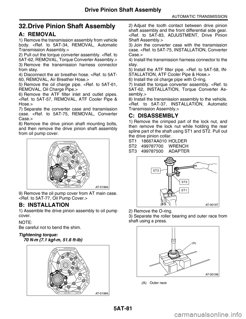
8) Remove the drive pinion shaft mounting bolts,
and then remove the drive pinion shaft assembly
from oil pump cover.
9) Remove the oil pump cover from AT main case.
B: INSTALLATION
1) Assemble the drive pinion assembly to oil pump
cover.
NOTE:
Be careful not to bend the shim.
Tightening torque:
70 N·m (7.1 kgf-m, 51.6 ft-lb)
2) Adjust the tooth contact between drive pinion
shaft assembly and the front differential side gear.
Shaft Assembly.>
3) Join the converter case with the transmission
case.
Case.>
4) Install the transmission harness connector to the
stay.
5) Install the ATF filter pipe.
STALLATION, ATF Cooler Pipe & Hose.>
6) Install the oil charge pipe with O-ring.
7) Install the torque converter assembly.
5AT-62, INSTALLATION, Torque Converter As-
sembly.>
8) Install the transmission assembly to the vehicle.
Transmission Assembly.>
C: DISASSEMBLY
1) Remove the crimped part of the lock nut, and
then remove the lock nut while holding the rear
spline part of the shaft using ST1 and ST2. Pull out
the drive pinion collar.
ST1 18667AA010 HOLDER
ST2 499787700 WRENCH
ST3 499787500 ADAPTER
2) Remove the O-ring.
3) Separate the roller bearing and outer race from
shaft using a press.
AT-01984
AT-01984
(A) Outer race
AT-00197
ST1
ST3
ST2
AT-00198
(A)
Page 2098 of 2453

5AT-82
Drive Pinion Shaft Assembly
AUTOMATIC TRANSMISSION
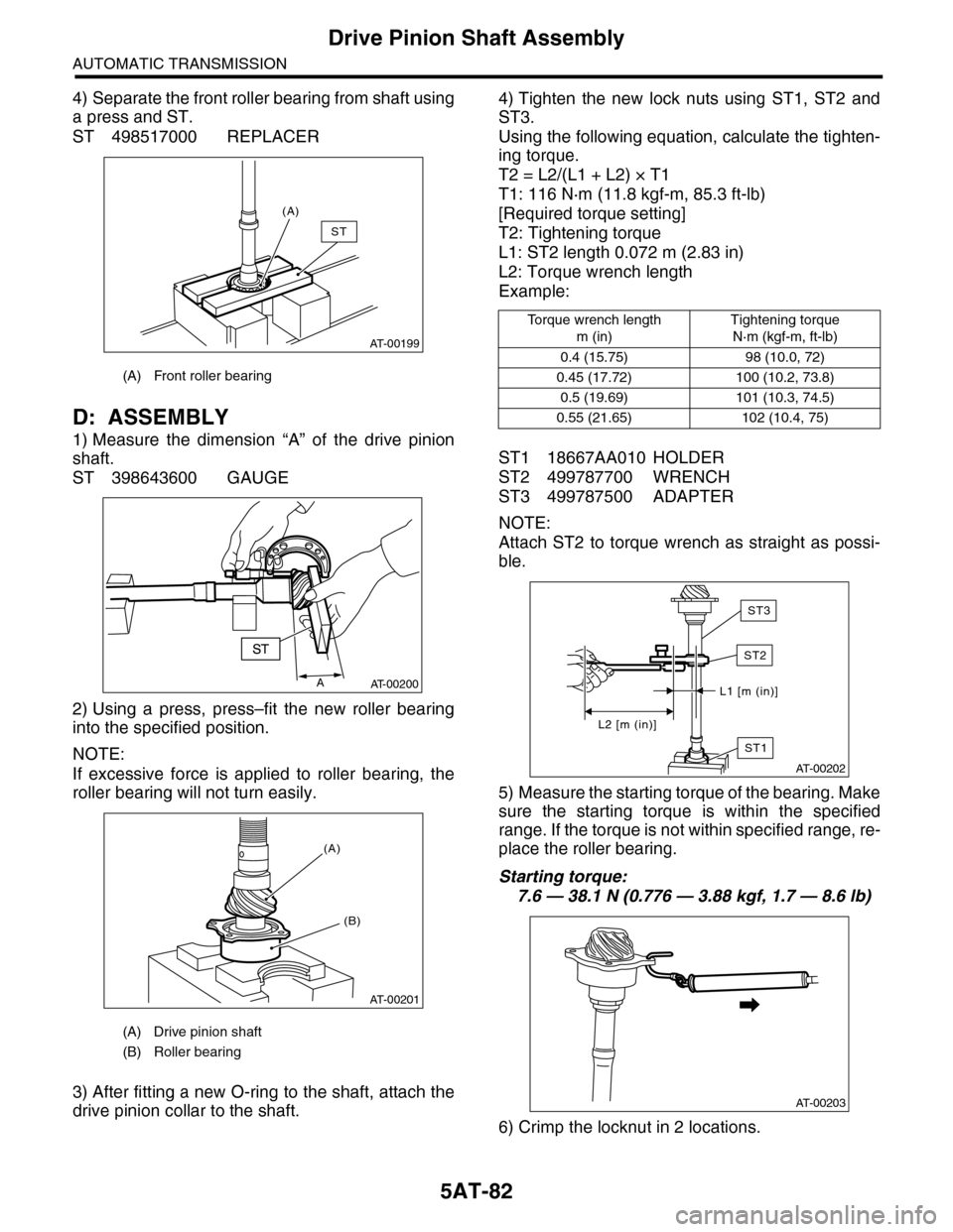
4) Separate the front roller bearing from shaft using
a press and ST.
ST 498517000 REPLACER
D: ASSEMBLY
1) Measure the dimension “A” of the drive pinion
shaft.
ST 398643600 GAUGE
2) Using a press, press–fit the new roller bearing
into the specified position.
NOTE:
If excessive force is applied to roller bearing, the
roller bearing will not turn easily.
3) After fitting a new O-ring to the shaft, attach the
drive pinion collar to the shaft.
4) Tighten the new lock nuts using ST1, ST2 and
ST3.
Using the following equation, calculate the tighten-
ing torque.
T2 = L2/(L1 + L2) × T1
T1: 116 N·m (11.8 kgf-m, 85.3 ft-lb)
[Required torque setting]
T2: Tightening torque
L1: ST2 length 0.072 m (2.83 in)
L2: Torque wrench length
Example:
ST1 18667AA010 HOLDER
ST2 499787700 WRENCH
ST3 499787500 ADAPTER
NOTE:
Attach ST2 to torque wrench as straight as possi-
ble.
5) Measure the starting torque of the bearing. Make
sure the starting torque is within the specified
range. If the torque is not within specified range, re-
place the roller bearing.
Starting torque:
7.6 — 38.1 N (0.776 — 3.88 kgf, 1.7 — 8.6 lb)
6) Crimp the locknut in 2 locations.
(A) Front roller bearing
(A) Drive pinion shaft
(B) Roller bearing
AT-00199
(A)
ST
AAT-00200
AT-00201
(B)
(A)
To r q u e w r e n c h l e n g t h
m (in)
Tightening torque
N·m (kgf-m, ft-lb)
0.4 (15.75) 98 (10.0, 72)
0.45 (17.72) 100 (10.2, 73.8)
0.5 (19.69) 101 (10.3, 74.5)
0.55 (21.65) 102 (10.4, 75)
ST1
AT-00202
L1 [m (in)]
L2 [m (in)]
ST2
ST3
AT-00203
Page 2101 of 2453
5AT-85
Drive Pinion Shaft Assembly
AUTOMATIC TRANSMISSION
6) If tooth contact is correct, mark the retainer posi-
tion and loosen it. After fitting a new O-ring and oil
seal, screw in the retainer to the marked position.
Tighten the lock plate with specified torque.
Tightening torque:
25 N·m (2.5 kgf-m, 18 ft-lb)
(A) Lock plate
AT-01988
(A)