Page 1940 of 2453
ME(H6DO)-74
Cylinder Block
MECHANICAL
5. CONNECTING ROD
1) Replace the connecting rod, if the large or small
end thrust surface is damaged.
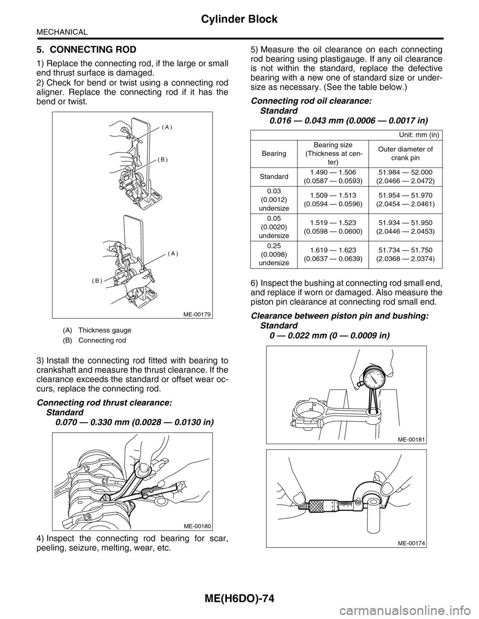
2) Check for bend or twist using a connecting rod
aligner. Replace the connecting rod if it has the
bend or twist.
3) Install the connecting rod fitted with bearing to
crankshaft and measure the thrust clearance. If the
clearance exceeds the standard or offset wear oc-
curs, replace the connecting rod.
Connecting rod thrust clearance:
Standard
0.070 — 0.330 mm (0.0028 — 0.0130 in)
4) Inspect the connecting rod bearing for scar,
peeling, seizure, melting, wear, etc.
5) Measure the oil clearance on each connecting
rod bearing using plastigauge. If any oil clearance
is not within the standard, replace the defective
bearing with a new one of standard size or under-
size as necessary. (See the table below.)
Connecting rod oil clearance:
Standard
0.016 — 0.043 mm (0.0006 — 0.0017 in)
6) Inspect the bushing at connecting rod small end,
and replace if worn or damaged. Also measure the
piston pin clearance at connecting rod small end.
Clearance between piston pin and bushing:
Standard
0 — 0.022 mm (0 — 0.0009 in)(A) Thickness gauge
(B) Connecting rod
(A)
(A)
(B)
(B)
ME-00179
ME-00180
Unit: mm (in)
Bearing
Bearing size
(Thickness at cen-
ter)
Outer diameter of
crank pin
Standard1.490 — 1.506
(0.0587 — 0.0593)
51.984 — 52.000
(2.0466 — 2.0472)
0.03
(0.0012)
undersize
1.509 — 1.513
(0.0594 — 0.0596)
51.954 — 51.970
(2.0454 — 2.0461)
0.05
(0.0020)
undersize
1.519 — 1.523
(0.0598 — 0.0600)
51.934 — 51.950
(2.0446 — 2.0453)
0.25
(0.0098)
undersize
1.619 — 1.623
(0.0637 — 0.0639)
51.734 — 51.750
(2.0368 — 2.0374)
ME-00181
ME-00174
Page 1941 of 2453
ME(H6DO)-75
Cylinder Block
MECHANICAL
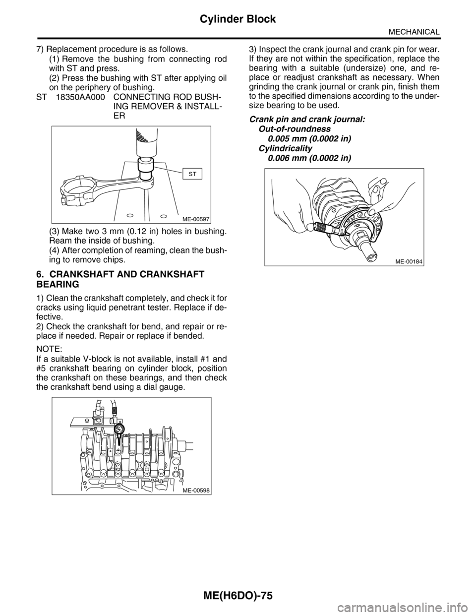
7) Replacement procedure is as follows.
(1) Remove the bushing from connecting rod
with ST and press.
(2) Press the bushing with ST after applying oil
on the periphery of bushing.
ST 18350AA000 CONNECTING ROD BUSH-
ING REMOVER & INSTALL-
ER
(3) Make two 3 mm (0.12 in) holes in bushing.
Ream the inside of bushing.
(4) After completion of reaming, clean the bush-
ing to remove chips.
6. CRANKSHAFT AND CRANKSHAFT
BEARING
1) Clean the crankshaft completely, and check it for
cracks using liquid penetrant tester. Replace if de-
fective.
2) Check the crankshaft for bend, and repair or re-
place if needed. Repair or replace if bended.
NOTE:
If a suitable V-block is not available, install #1 and
#5 crankshaft bearing on cylinder block, position
the crankshaft on these bearings, and then check
the crankshaft bend using a dial gauge.
3) Inspect the crank journal and crank pin for wear.
If they are not within the specification, replace the
bearing with a suitable (undersize) one, and re-
place or readjust crankshaft as necessary. When
grinding the crank journal or crank pin, finish them
to the specified dimensions according to the under-
size bearing to be used.
Crank pin and crank journal:
Out-of-roundness
0.005 mm (0.0002 in)
Cylindricality
0.006 mm (0.0002 in)
ST
ME-00597
ME-00598
ME-00184
Page 1942 of 2453
ME(H6DO)-76
Cylinder Block
MECHANICAL
4) Measure the thrust clearance of crankshaft at
center bearing. If clearance exceeds the standard,
replace the bearing.
Crankshaft thrust clearance:
Standard
0.030 — 0.115 mm (0.0012 — 0.0045 in)
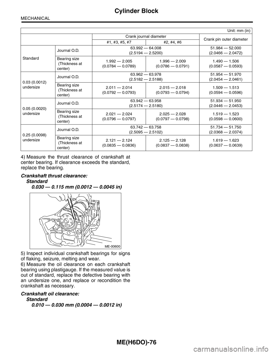
5) Inspect individual crankshaft bearings for signs
of flaking, seizure, melting and wear.
6) Measure the oil clearance on each crankshaft
bearing using plastigauge. If the measured value is
out of standard, replace the defective bearing with
an undersize one, and replace or recondition the
crankshaft as necessary.
Crankshaft oil clearance:
Standard
0.010 — 0.030 mm (0.0004 — 0.0012 in)
Unit: mm (in)
Crank journal diameterCrank pin outer diameter#1, #3, #5, #7 #2, #4, #6
Standard
Journal O.D.63.992 — 64.008
(2.5194 — 2.5200)
51.984 — 52.000
(2.0466 — 2.0472)
Bearing size
(Thickness at
center)
1.992 — 2.005
(0.0784 — 0.0789)
1.996 — 2.009
(0.0786 — 0.0791)
1.490 — 1.506
(0.0587 — 0.0593)
0.03 (0.0012)
undersize
Journal O.D.63.962 — 63.978
(2.5182 — 2.5188)
51.954 — 51.970
(2.0454 — 2.0461)
Bearing size
(Thickness at
center)
2.011 — 2.014
(0.0792 — 0.0793)
2.015 — 2.018
(0.0793 — 0.0794)
1.509 — 1.513
(0.0594 — 0.0596)
0.05 (0.0020)
undersize
Journal O.D.63.942 — 63.958
(2.5174 — 2.5180)
51.934 — 51.950
(2.0446 — 2.0453)
Bearing size
(Thickness at
center)
2.021 — 2.024
(0.0796 — 0.0797)
2.025 — 2.028
(0.0797 — 0.0798)
1.519 — 1.523
(0.0598 — 0.0600)
0.25 (0.0098)
undersize
Journal O.D.63.742 — 63.758
(2.5095 — 2.5102)
51.734 — 51.750
(2.0368 — 2.0374)
Bearing size
(Thickness at
center)
2.121 — 2.124
(0.0835 — 0.0836)
2.125 — 2.128
(0.0837 — 0.0838)
1.619 — 1.623
(0.0637 — 0.0639)
ME-00600
Page 1946 of 2453
ME(H6DO)-80
Piston
MECHANICAL
25.Piston
A: SPECIFICATION
Refer to “Cylinder Block” for removal and installa-
tion procedures of pistons.
REMOVAL, Cylinder Block.>
64, INSTALLATION, Cylinder Block.>
Page 1947 of 2453
ME(H6DO)-81
Connecting Rod
MECHANICAL
26.Connecting Rod
A: SPECIFICATION
Refer to “Cylinder Block” for removal and installa-
tion procedures of connecting rod.
Block.>
Cylinder Block.>
Page 1948 of 2453
ME(H6DO)-82
Crankshaft
MECHANICAL
27.Crankshaft
A: SPECIFICATION
Refer to “Cylinder Block” for removal and installa-
tion procedures of crankshaft.
62, REMOVAL, Cylinder Block.>
ME(H6DO)-64, INSTALLATION, Cylinder Block.>
Page 1960 of 2453
SC(H6DO)-2
General Description
STARTING/CHARGING SYSTEMS
1. General Description
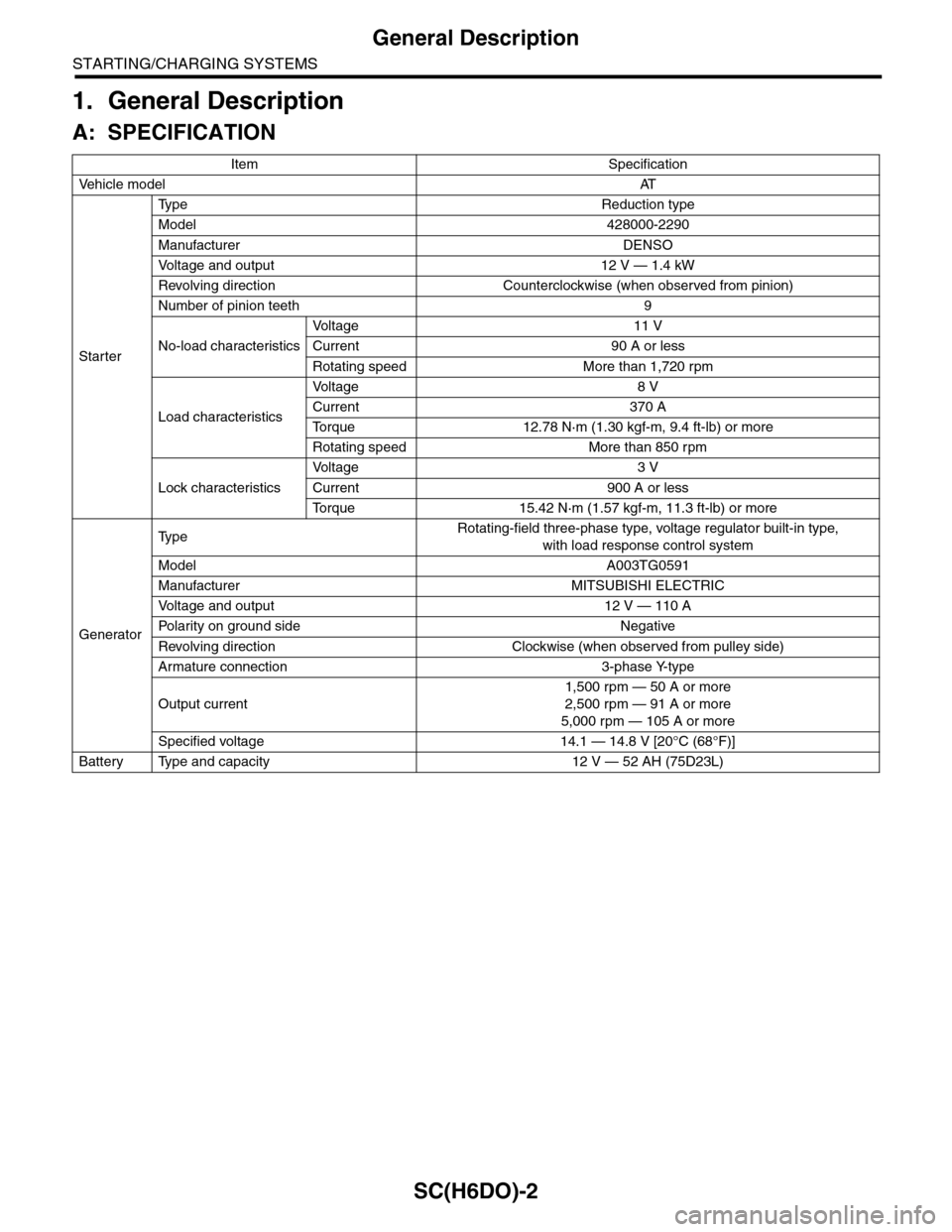
A: SPECIFICATION
Item Specification
Ve h i c l e m o d e lAT
Starter
Ty p e R e d u c t i o n t y p e
Model 428000-2290
Manufacturer DENSO
Vo l t a g e a n d o u t p u t 1 2 V — 1 . 4 k W
Revolving direction Counterclockwise (when observed from pinion)
Number of pinion teeth 9
No-load characteristics
Vo l t a g e 1 1 V
Current 90 A or less
Rotating speed More than 1,720 rpm
Load characteristics
Vo l t a g e 8 V
Current 370 A
To r q u e 1 2 . 7 8 N · m ( 1 . 3 0 k g f - m , 9 . 4 f t - l b ) o r m o r e
Rotating speed More than 850 rpm
Lock characteristics
Vo l t a g e 3 V
Current 900 A or less
To r q u e 1 5 . 4 2 N · m ( 1 . 5 7 k g f - m , 1 1 . 3 f t - l b ) o r m o r e
Generator
Ty p eRotating-field three-phase type, voltage regulator built-in type,
with load response control system
Model A003TG0591
Manufacturer MITSUBISHI ELECTRIC
Vo l t a g e a n d o u t p u t 1 2 V — 1 1 0 A
Po la r i t y on gr ou n d s id e N e g at i ve
Revolving direction Clockwise (when observed from pulley side)
Armature connection 3-phase Y-type
Output current
1,500 rpm — 50 A or more
2,500 rpm — 91 A or more
5,000 rpm — 105 A or more
Specified voltage 14.1 — 14.8 V [20°C (68°F)]
Battery Type and capacity 12 V — 52 AH (75D23L)
Page 1973 of 2453
SC(H6DO)-15
Starter
STARTING/CHARGING SYSTEMS
E: INSPECTION
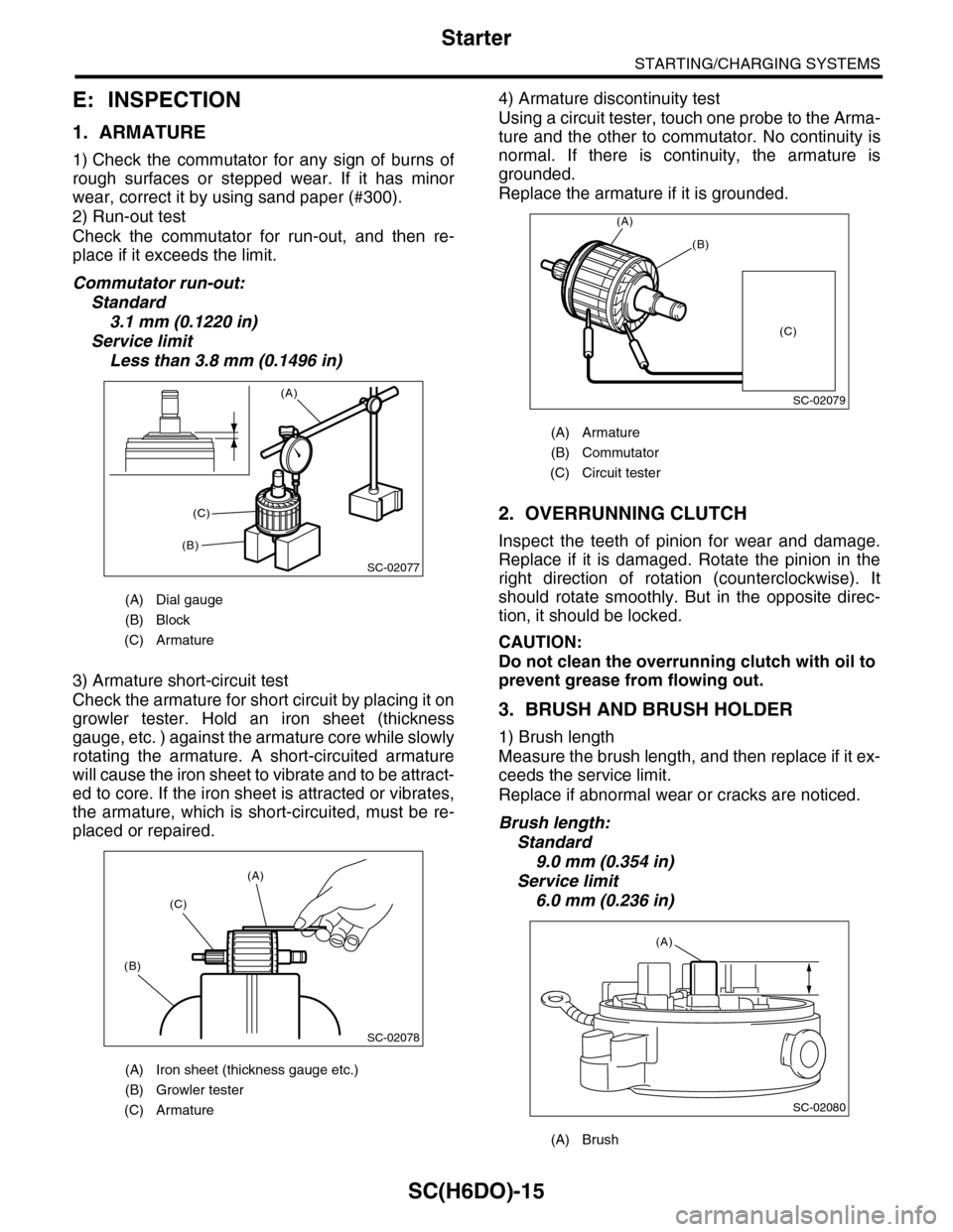
1. ARMATURE
1) Check the commutator for any sign of burns of
rough surfaces or stepped wear. If it has minor
wear, correct it by using sand paper (#300).
2) Run-out test
Check the commutator for run-out, and then re-
place if it exceeds the limit.
Commutator run-out:
Standard
3.1 mm (0.1220 in)
Service limit
Less than 3.8 mm (0.1496 in)
3) Armature short-circuit test
Check the armature for short circuit by placing it on
growler tester. Hold an iron sheet (thickness
gauge, etc. ) against the armature core while slowly
rotating the armature. A short-circuited armature
will cause the iron sheet to vibrate and to be attract-
ed to core. If the iron sheet is attracted or vibrates,
the armature, which is short-circuited, must be re-
placed or repaired.
4) Armature discontinuity test
Using a circuit tester, touch one probe to the Arma-
ture and the other to commutator. No continuity is
normal. If there is continuity, the armature is
grounded.
Replace the armature if it is grounded.
2. OVERRUNNING CLUTCH
Inspect the teeth of pinion for wear and damage.
Replace if it is damaged. Rotate the pinion in the
right direction of rotation (counterclockwise). It
should rotate smoothly. But in the opposite direc-
tion, it should be locked.
CAUTION:
Do not clean the overrunning clutch with oil to
prevent grease from flowing out.
3. BRUSH AND BRUSH HOLDER
1) Brush length
Measure the brush length, and then replace if it ex-
ceeds the service limit.
Replace if abnormal wear or cracks are noticed.
Brush length:
Standard
9.0 mm (0.354 in)
Service limit
6.0 mm (0.236 in)
(A) Dial gauge
(B) Block
(C) Armature
(A) Iron sheet (thickness gauge etc.)
(B) Growler tester
(C) Armature
SC-02077
(A)
(B)
(C)
SC-02078
(A)
(C)
(B)
(A) Armature
(B) Commutator
(C) Circuit tester
(A) Brush
SC-02079
(A)
(B)
(C)
SC-02080
(A)