2009 SUBARU TRIBECA lock
[x] Cancel search: lockPage 2202 of 2453
5AT(diag)-85
Diagnostic Procedure with Diagnostic Trouble Code (DTC)
AUTOMATIC TRANSMISSION (DIAGNOSTICS)
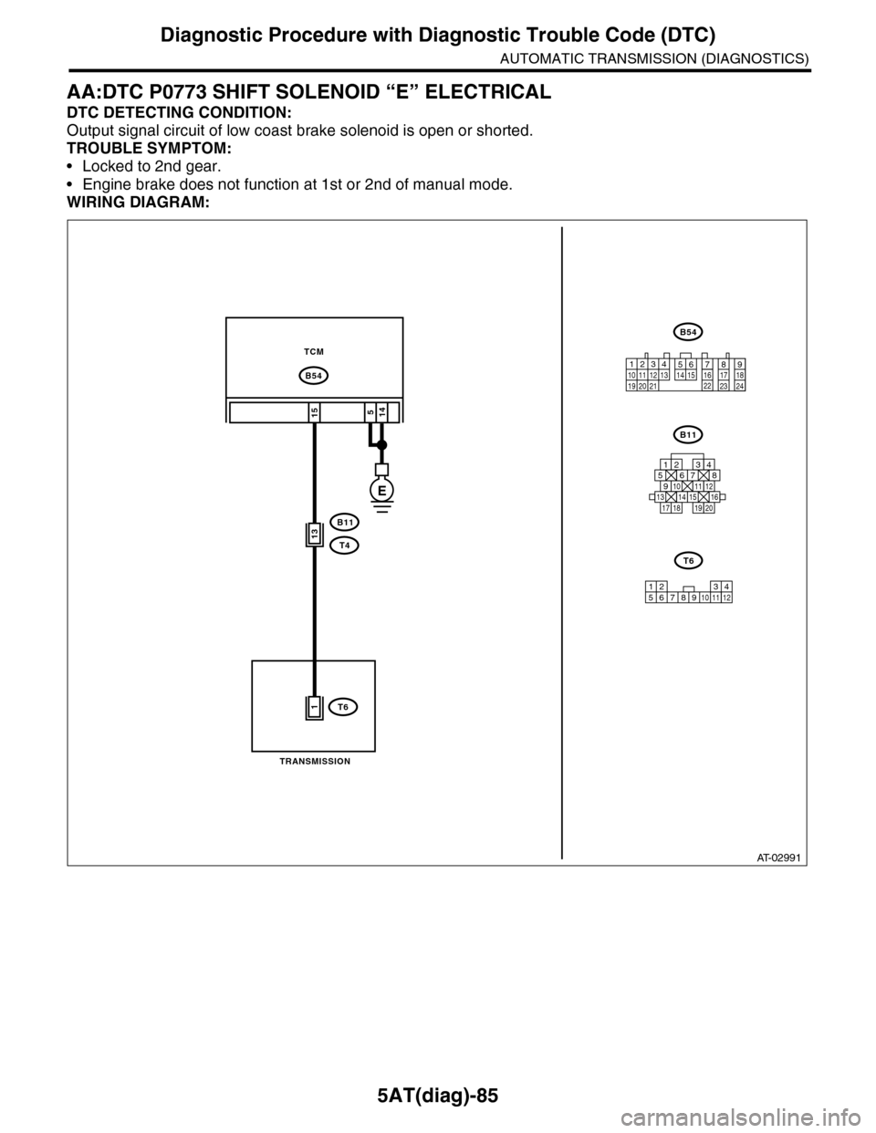
AA:DTC P0773 SHIFT SOLENOID “E” ELECTRICAL
DTC DETECTING CONDITION:
Output signal circuit of low coast brake solenoid is open or shorted.
TROUBLE SYMPTOM:
•Locked to 2nd gear.
•Engine brake does not function at 1st or 2nd of manual mode.
WIRING DIAGRAM:
AT-02991
B54
15
B11
TCM
B54
B11
125678
131415169101112
34
17181920
TRANSMISSION
12789563410 11 1219 20 2113 14 15 16 17 18222324
T4
T6
12586910 113412
T6
7
E
514
1
13
Page 2205 of 2453
5AT(diag)-88
Diagnostic Procedure with Diagnostic Trouble Code (DTC)
AUTOMATIC TRANSMISSION (DIAGNOSTICS)
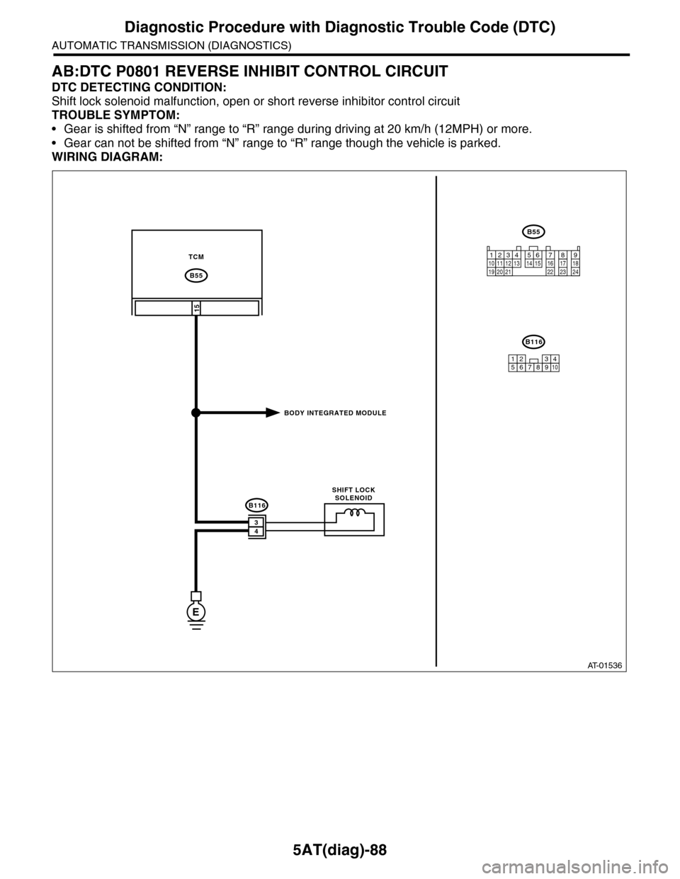
AB:DTC P0801 REVERSE INHIBIT CONTROL CIRCUIT
DTC DETECTING CONDITION:
Shift lock solenoid malfunction, open or short reverse inhibitor control circuit
TROUBLE SYMPTOM:
•Gear is shifted from “N” range to “R” range during driving at 20 km/h (12MPH) or more.
•Gear can not be shifted from “N” range to “R” range though the vehicle is parked.
WIRING DIAGRAM:
AT-01536
TCM
15
B55
E
B116
B55
B116
34
BODY INTEGRATED MODULE
SHIFT LOCKSOLENOID
12341011 121920 21135614 1578916 17 1822 23 24
12345678910
Page 2206 of 2453
5AT(diag)-89
Diagnostic Procedure with Diagnostic Trouble Code (DTC)
AUTOMATIC TRANSMISSION (DIAGNOSTICS)
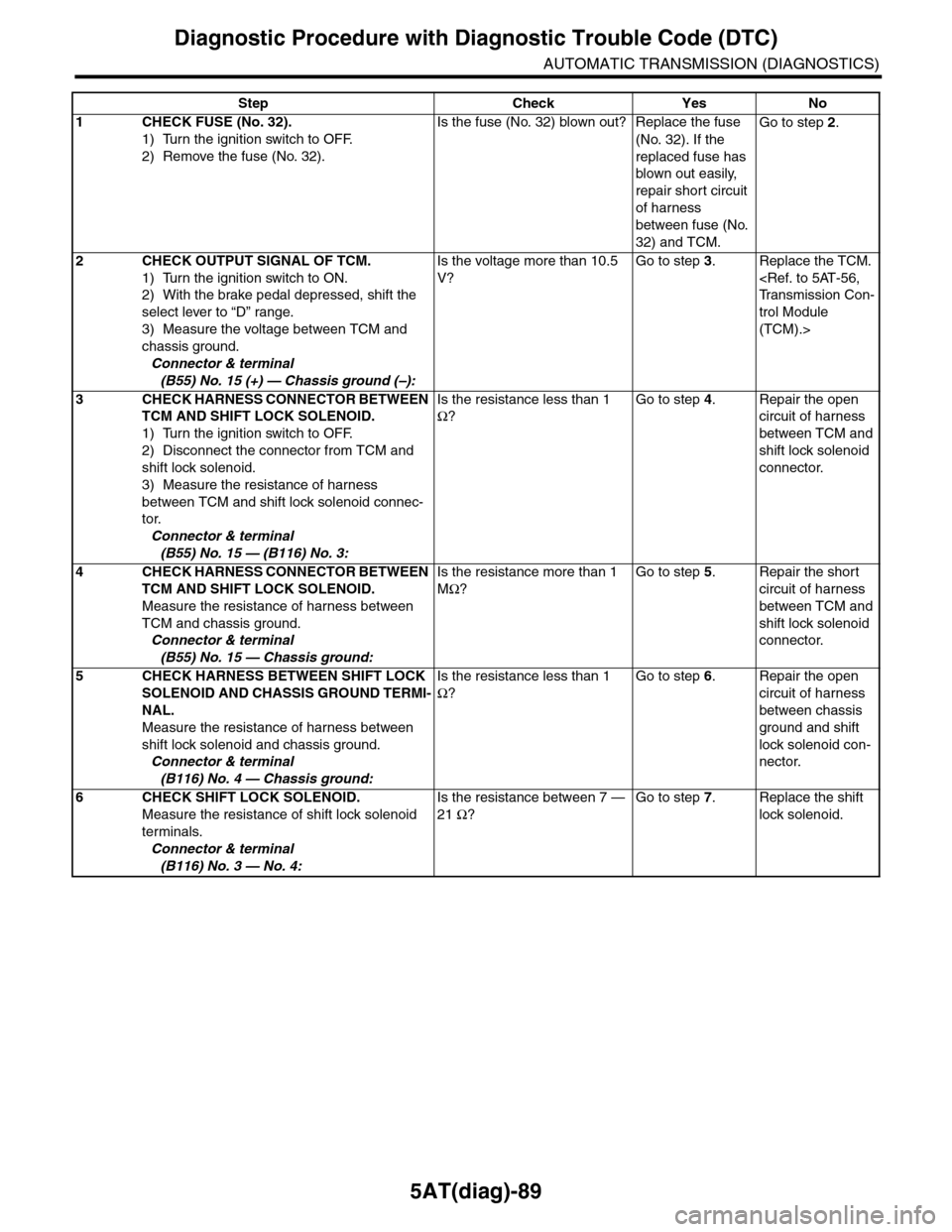
Step Check Yes No
1CHECK FUSE (No. 32).
1) Turn the ignition switch to OFF.
2) Remove the fuse (No. 32).
Is the fuse (No. 32) blown out? Replace the fuse
(No. 32). If the
replaced fuse has
blown out easily,
repair short circuit
of harness
between fuse (No.
32) and TCM.
Go to step 2.
2CHECK OUTPUT SIGNAL OF TCM.
1) Turn the ignition switch to ON.
2) With the brake pedal depressed, shift the
select lever to “D” range.
3) Measure the voltage between TCM and
chassis ground.
Connector & terminal
(B55) No. 15 (+) — Chassis ground (–):
Is the voltage more than 10.5
V?
Go to step 3.Replace the TCM.
trol Module
(TCM).>
3CHECK HARNESS CONNECTOR BETWEEN
TCM AND SHIFT LOCK SOLENOID.
1) Turn the ignition switch to OFF.
2) Disconnect the connector from TCM and
shift lock solenoid.
3) Measure the resistance of harness
between TCM and shift lock solenoid connec-
tor.
Connector & terminal
(B55) No. 15 — (B116) No. 3:
Is the resistance less than 1
Ω?
Go to step 4.Repair the open
circuit of harness
between TCM and
shift lock solenoid
connector.
4CHECK HARNESS CONNECTOR BETWEEN
TCM AND SHIFT LOCK SOLENOID.
Measure the resistance of harness between
TCM and chassis ground.
Connector & terminal
(B55) No. 15 — Chassis ground:
Is the resistance more than 1
MΩ?
Go to step 5.Repair the short
circuit of harness
between TCM and
shift lock solenoid
connector.
5CHECK HARNESS BETWEEN SHIFT LOCK
SOLENOID AND CHASSIS GROUND TERMI-
NAL.
Measure the resistance of harness between
shift lock solenoid and chassis ground.
Connector & terminal
(B116) No. 4 — Chassis ground:
Is the resistance less than 1
Ω?
Go to step 6.Repair the open
circuit of harness
between chassis
ground and shift
lock solenoid con-
nector.
6CHECK SHIFT LOCK SOLENOID.
Measure the resistance of shift lock solenoid
terminals.
Connector & terminal
(B116) No. 3 — No. 4:
Is the resistance between 7 —
21 Ω?
Go to step 7.Replace the shift
lock solenoid.
Page 2233 of 2453
5AT(diag)-116
Diagnostic Procedure with Diagnostic Trouble Code (DTC)
AUTOMATIC TRANSMISSION (DIAGNOSTICS)
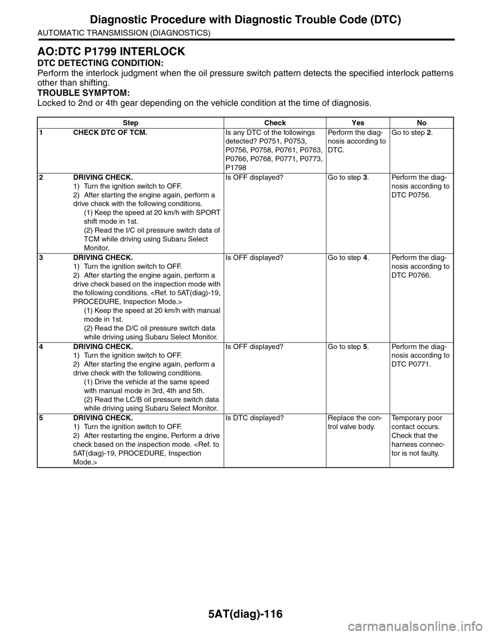
AO:DTC P1799 INTERLOCK
DTC DETECTING CONDITION:
Perform the interlock judgment when the oil pressure switch pattern detects the specified interlock patterns
other than shifting.
TROUBLE SYMPTOM:
Locked to 2nd or 4th gear depending on the vehicle condition at the time of diagnosis.
Step Check Yes No
1CHECK DTC OF TCM.Is any DTC of the followings
detected? P0751, P0753,
P0756, P0758, P0761, P0763,
P0766, P0768, P0771, P0773,
P1798
Pe r for m t h e d ia g -
nosis according to
DTC.
Go to step 2.
2DRIVING CHECK.
1) Turn the ignition switch to OFF.
2) After starting the engine again, perform a
drive check with the following conditions.
(1) Keep the speed at 20 km/h with SPORT
shift mode in 1st.
(2) Read the I/C oil pressure switch data of
TCM while driving using Subaru Select
Monitor.
Is OFF displayed? Go to step 3.Perform the diag-
nosis according to
DTC P0756.
3DRIVING CHECK.
1) Turn the ignition switch to OFF.
2) After starting the engine again, perform a
drive check based on the inspection mode with
the following conditions.
(1) Keep the speed at 20 km/h with manual
mode in 1st.
(2) Read the D/C oil pressure switch data
while driving using Subaru Select Monitor.
Is OFF displayed? Go to step 4.Perform the diag-
nosis according to
DTC P0766.
4DRIVING CHECK.
1) Turn the ignition switch to OFF.
2) After starting the engine again, perform a
drive check with the following conditions.
(1) Drive the vehicle at the same speed
with manual mode in 3rd, 4th and 5th.
(2) Read the LC/B oil pressure switch data
while driving using Subaru Select Monitor.
Is OFF displayed? Go to step 5.Perform the diag-
nosis according to
DTC P0771.
5DRIVING CHECK.
1) Turn the ignition switch to OFF.
2) After restarting the engine, Perform a drive
check based on the inspection mode.
Mode.>
Is DTC displayed? Replace the con-
trol valve body.
Te m p o r a r y p o o r
contact occurs.
Check that the
harness connec-
tor is not faulty.
Page 2246 of 2453
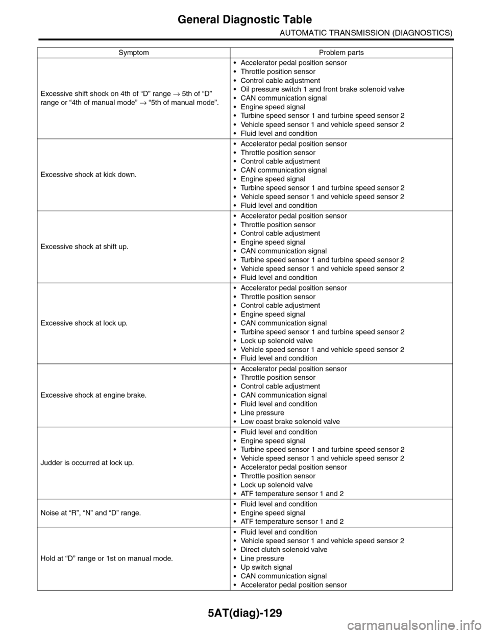
5AT(diag)-129
General Diagnostic Table
AUTOMATIC TRANSMISSION (DIAGNOSTICS)
Excessive shift shock on 4th of “D” range → 5th of “D”
range or “4th of manual mode” → “5th of manual mode”.
•Accelerator pedal position sensor
•Throttle position sensor
•Control cable adjustment
•Oil pressure switch 1 and front brake solenoid valve
•CAN communication signal
•Engine speed signal
•Turbine speed sensor 1 and turbine speed sensor 2
•Vehicle speed sensor 1 and vehicle speed sensor 2
•Fluid level and condition
Excessive shock at kick down.
•Accelerator pedal position sensor
•Throttle position sensor
•Control cable adjustment
•CAN communication signal
•Engine speed signal
•Turbine speed sensor 1 and turbine speed sensor 2
•Vehicle speed sensor 1 and vehicle speed sensor 2
•Fluid level and condition
Excessive shock at shift up.
•Accelerator pedal position sensor
•Throttle position sensor
•Control cable adjustment
•Engine speed signal
•CAN communication signal
•Turbine speed sensor 1 and turbine speed sensor 2
•Vehicle speed sensor 1 and vehicle speed sensor 2
•Fluid level and condition
Excessive shock at lock up.
•Accelerator pedal position sensor
•Throttle position sensor
•Control cable adjustment
•Engine speed signal
•CAN communication signal
•Turbine speed sensor 1 and turbine speed sensor 2
•Lock up solenoid valve
•Vehicle speed sensor 1 and vehicle speed sensor 2
•Fluid level and condition
Excessive shock at engine brake.
•Accelerator pedal position sensor
•Throttle position sensor
•Control cable adjustment
•CAN communication signal
•Fluid level and condition
•Line pressure
•Low coast brake solenoid valve
Judder is occurred at lock up.
•Fluid level and condition
•Engine speed signal
•Turbine speed sensor 1 and turbine speed sensor 2
•Vehicle speed sensor 1 and vehicle speed sensor 2
•Accelerator pedal position sensor
•Throttle position sensor
•Lock up solenoid valve
•ATF temperature sensor 1 and 2
Noise at “R”, “N” and “D” range.
•Fluid level and condition
•Engine speed signal
•ATF temperature sensor 1 and 2
Hold at “D” range or 1st on manual mode.
•Fluid level and condition
•Vehicle speed sensor 1 and vehicle speed sensor 2
•Direct clutch solenoid valve
•Line pressure
•Up switch signal
•CAN communication signal
•Accelerator pedal position sensor
Symptom Problem parts
Page 2248 of 2453
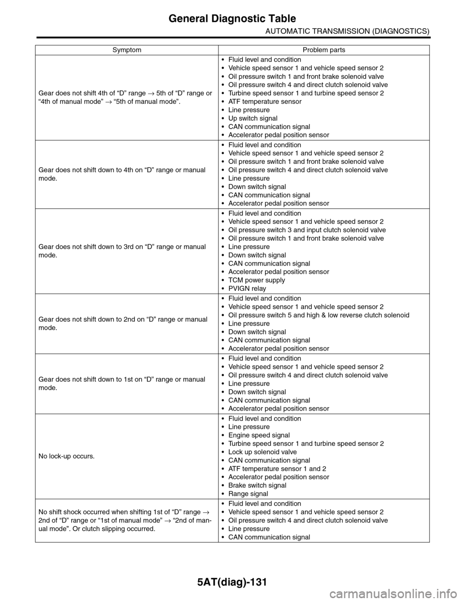
5AT(diag)-131
General Diagnostic Table
AUTOMATIC TRANSMISSION (DIAGNOSTICS)
Gear does not shift 4th of “D” range → 5th of “D” range or
“4th of manual mode” → “5th of manual mode”.
•Fluid level and condition
•Vehicle speed sensor 1 and vehicle speed sensor 2
•Oil pressure switch 1 and front brake solenoid valve
•Oil pressure switch 4 and direct clutch solenoid valve
•Turbine speed sensor 1 and turbine speed sensor 2
•ATF temperature sensor
•Line pressure
•Up switch signal
•CAN communication signal
•Accelerator pedal position sensor
Gear does not shift down to 4th on “D” range or manual
mode.
•Fluid level and condition
•Vehicle speed sensor 1 and vehicle speed sensor 2
•Oil pressure switch 1 and front brake solenoid valve
•Oil pressure switch 4 and direct clutch solenoid valve
•Line pressure
•Down switch signal
•CAN communication signal
•Accelerator pedal position sensor
Gear does not shift down to 3rd on “D” range or manual
mode.
•Fluid level and condition
•Vehicle speed sensor 1 and vehicle speed sensor 2
•Oil pressure switch 3 and input clutch solenoid valve
•Oil pressure switch 1 and front brake solenoid valve
•Line pressure
•Down switch signal
•CAN communication signal
•Accelerator pedal position sensor
•TCM power supply
•PVIGN relay
Gear does not shift down to 2nd on “D” range or manual
mode.
•Fluid level and condition
•Vehicle speed sensor 1 and vehicle speed sensor 2
•Oil pressure switch 5 and high & low reverse clutch solenoid
•Line pressure
•Down switch signal
•CAN communication signal
•Accelerator pedal position sensor
Gear does not shift down to 1st on “D” range or manual
mode.
•Fluid level and condition
•Vehicle speed sensor 1 and vehicle speed sensor 2
•Oil pressure switch 4 and direct clutch solenoid valve
•Line pressure
•Down switch signal
•CAN communication signal
•Accelerator pedal position sensor
No lock-up occurs.
•Fluid level and condition
•Line pressure
•Engine speed signal
•Turbine speed sensor 1 and turbine speed sensor 2
•Lock up solenoid valve
•CAN communication signal
•ATF temperature sensor 1 and 2
•Accelerator pedal position sensor
•Brake switch signal
•Range signal
No shift shock occurred when shifting 1st of “D” range →
2nd of “D” range or “1st of manual mode” → “2nd of man-
ual mode”. Or clutch slipping occurred.
•Fluid level and condition
•Vehicle speed sensor 1 and vehicle speed sensor 2
•Oil pressure switch 4 and direct clutch solenoid valve
•Line pressure
•CAN communication signal
Symptom Problem parts
Page 2251 of 2453
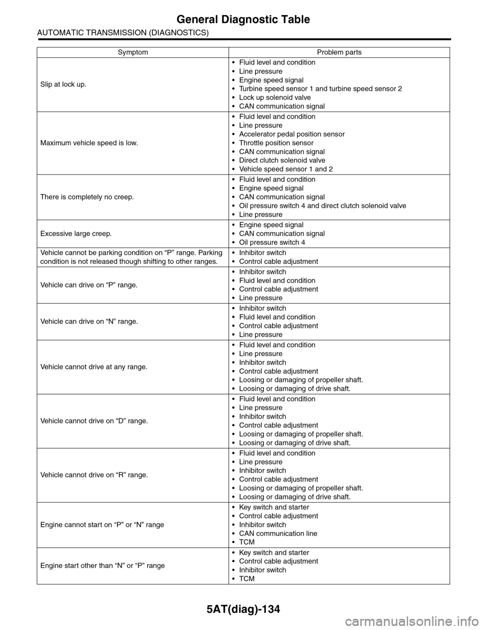
5AT(diag)-134
General Diagnostic Table
AUTOMATIC TRANSMISSION (DIAGNOSTICS)
Slip at lock up.
•Fluid level and condition
•Line pressure
•Engine speed signal
•Turbine speed sensor 1 and turbine speed sensor 2
•Lock up solenoid valve
•CAN communication signal
Maximum vehicle speed is low.
•Fluid level and condition
•Line pressure
•Accelerator pedal position sensor
•Throttle position sensor
•CAN communication signal
•Direct clutch solenoid valve
•Vehicle speed sensor 1 and 2
There is completely no creep.
•Fluid level and condition
•Engine speed signal
•CAN communication signal
•Oil pressure switch 4 and direct clutch solenoid valve
•Line pressure
Excessive large creep.
•Engine speed signal
•CAN communication signal
•Oil pressure switch 4
Ve h i c l e c a n n o t b e p a r k i n g c o n d i t i o n o n “ P ” r a n g e . Pa r k i n g
condition is not released though shifting to other ranges.
•Inhibitor switch
•Control cable adjustment
Ve h i c l e c a n d r i v e o n “ P ” r a n g e .
•Inhibitor switch
•Fluid level and condition
•Control cable adjustment
•Line pressure
Ve h i c l e c a n d r i v e o n “ N ” r a n g e .
•Inhibitor switch
•Fluid level and condition
•Control cable adjustment
•Line pressure
Ve h i c l e c a n n o t d r i v e a t a n y r a n g e .
•Fluid level and condition
•Line pressure
•Inhibitor switch
•Control cable adjustment
•Loosing or damaging of propeller shaft.
•Loosing or damaging of drive shaft.
Ve h i c l e c a n n o t d r i v e o n “ D ” r a n g e .
•Fluid level and condition
•Line pressure
•Inhibitor switch
•Control cable adjustment
•Loosing or damaging of propeller shaft.
•Loosing or damaging of drive shaft.
Ve h i c l e c a n n o t d r i v e o n “ R ” r a n g e .
•Fluid level and condition
•Line pressure
•Inhibitor switch
•Control cable adjustment
•Loosing or damaging of propeller shaft.
•Loosing or damaging of drive shaft.
Engine cannot start on “P” or “N” range
•Key switch and starter
•Control cable adjustment
•Inhibitor switch
•CAN communication line
•TCM
Engine start other than “N” or “P” range
•Key switch and starter
•Control cable adjustment
•Inhibitor switch
•TCM
Symptom Problem parts
Page 2252 of 2453
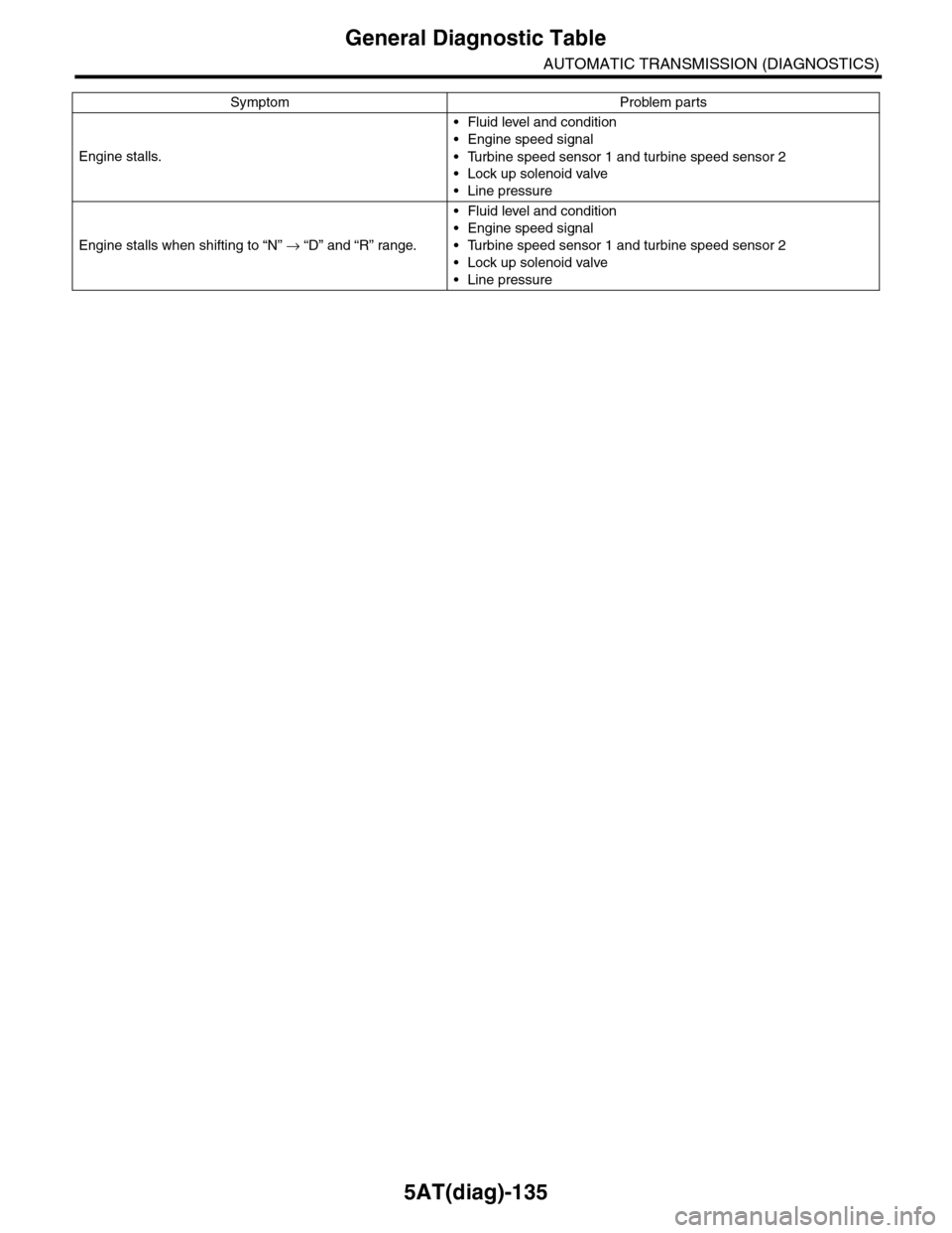
5AT(diag)-135
General Diagnostic Table
AUTOMATIC TRANSMISSION (DIAGNOSTICS)
Engine stalls.
•Fluid level and condition
•Engine speed signal
•Turbine speed sensor 1 and turbine speed sensor 2
•Lock up solenoid valve
•Line pressure
Engine stalls when shifting to “N” → “D” and “R” range.
•Fluid level and condition
•Engine speed signal
•Turbine speed sensor 1 and turbine speed sensor 2
•Lock up solenoid valve
•Line pressure
Symptom Problem parts