Page 2283 of 2453
CS-31
AT Shift Lock Solenoid and “P” Range Switch
CONTROL SYSTEMS
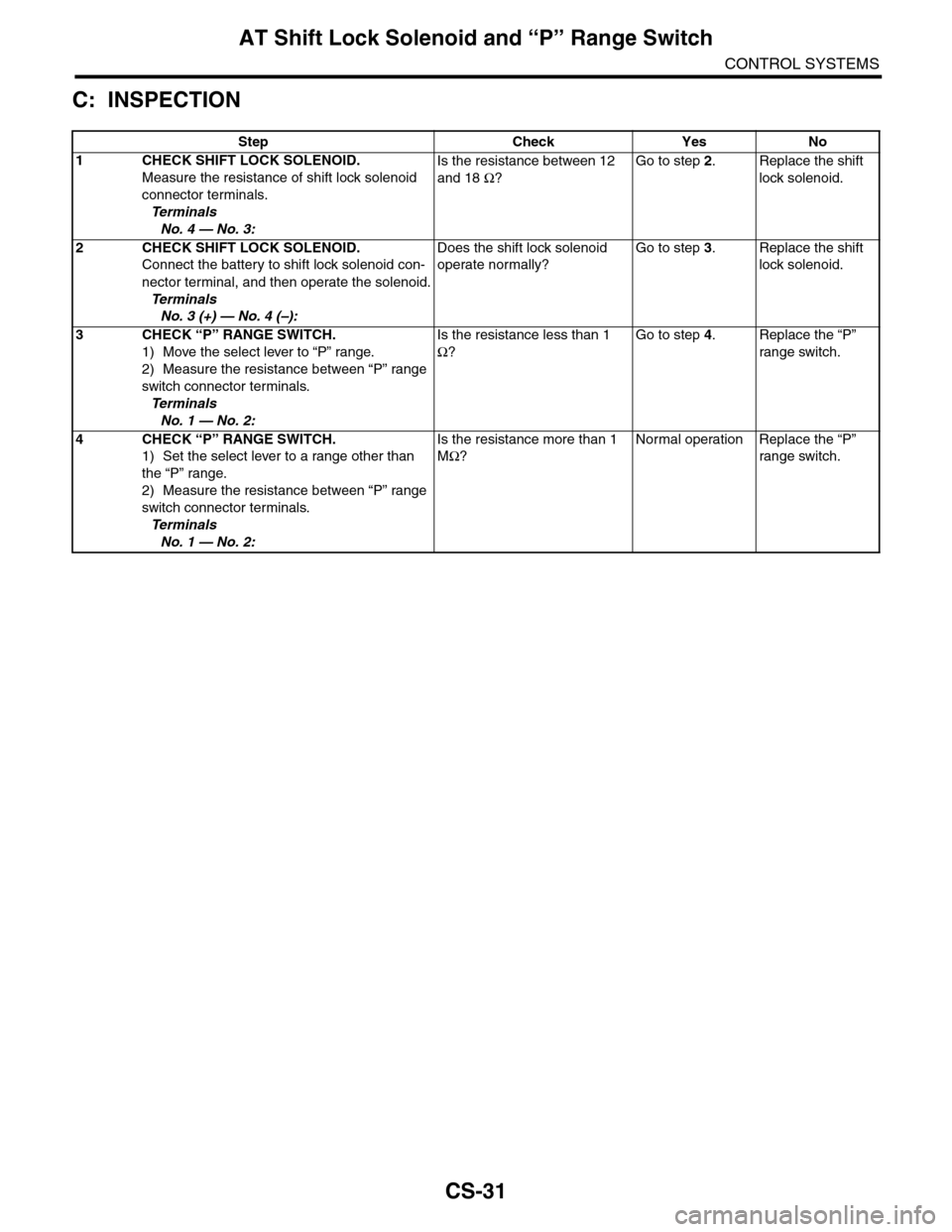
C: INSPECTION
Step Check Yes No
1CHECK SHIFT LOCK SOLENOID.
Measure the resistance of shift lock solenoid
connector terminals.
Te r m i n a l s
No. 4 — No. 3:
Is the resistance between 12
and 18 Ω?
Go to step 2.Replace the shift
lock solenoid.
2CHECK SHIFT LOCK SOLENOID.
Connect the battery to shift lock solenoid con-
nector terminal, and then operate the solenoid.
Te r m i n a l s
No. 3 (+) — No. 4 (–):
Does the shift lock solenoid
operate normally?
Go to step 3.Replace the shift
lock solenoid.
3CHECK “P” RANGE SWITCH.
1) Move the select lever to “P” range.
2) Measure the resistance between “P” range
switch connector terminals.
Te r m i n a l s
No. 1 — No. 2:
Is the resistance less than 1
Ω?
Go to step 4.Replace the “P”
range switch.
4CHECK “P” RANGE SWITCH.
1) Set the select lever to a range other than
the “P” range.
2) Measure the resistance between “P” range
switch connector terminals.
Te r m i n a l s
No. 1 — No. 2:
Is the resistance more than 1
MΩ?
Normal operation Replace the “P”
range switch.
Page 2289 of 2453
WI-5
Basic Diagnostic Procedure
WIRING SYSTEM
C: HOW TO READ WIRING DIA-
GRAMS
1. WIRING DIAGRAM
The wiring diagram of each system is illustrated so
that you can understand the path through which the
electric current flows from the battery.
Sketches and codes are used in the diagrams.
They should read as follows:
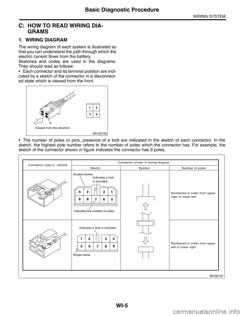
•Each connector and its terminal position are indi-
cated by a sketch of the connector in a disconnect-
ed state which is viewed from the front.
•The number of poles or pins, presence of a lock are indicated in the sketch of each connector. In the
sketch, the highest pole number refers to the number of poles which the connector has. For example, the
sketch of the connector shown in figure indicates the connector has 9 poles.
WI-02746
Viewed from this direction
4
2
4
1
3
WI-02747
Connector used in vehicleSketch Symbol Number of poles
Numbered in order from upperright to lower left.
Numbered in order from upperleft to lower right
Connector shown in wiring diagram
Double framesIndicates a lock is included.
Indicates the number of poles.
4321
98765
Indicates a lock is included.
Single frame
1234
56789
Page 2297 of 2453
WI-13
Basic Diagnostic Procedure
WIRING SYSTEM
F: ABBREVIATION IN WIRING DIA-
GRAMS
Abbr. Full name
A/C Air conditioner
A/FAir/Fuel
(Air fuel ratio sensor)
ABS Anti-lock Brake System
ACC Accessor y
AT E l e c t r o n i c a l l y c o n t r o l l e d f u l l y - a u t o m a t i c
AUX Auxiliar y
AW D A ll W he e l D r i ve
CAN Controller Area Network
CPC Canister Purge Control
CPU Central Processing Unit
ECM Engine Control Module (ECM)
EEPROMElectronically Erasable and Programma-
ble Read Only Memory
F/B Fuse & Relay box
FWD Front Wheel Drive
H/L Headlight
I/F Interface
IG Ignition
L, LH Left Hand
LCD Liquid Crystal Display
M/B Main fuse box
MFD Multi Function Display
OP Optional Parts or Open
PWM Pulse Width Modulation
R, RH Right Hand
SBF Slow Blow Fuse
ST Starter
TCS Traction Control System
TCM AT Control Module
TPM Tire Pressure Monitor
TV Television
U, UP Up
VDC Vehicle Dynamics Control
VVL Variable Valve Lift
Page 2298 of 2453
WI-14
Working Precautions
WIRING SYSTEM
2. Working Precautions
A: PRECAUTIONS WHEN WORKING
WITH THE PARTS MOUNTED ON
THE VEHICLE
1) When working under a vehicle which is jacked-
up, always be sure to use rigid rack.
2) The parking brake must always be applied dur-
ing working. Also, in automatic transmission vehi-
cles, keep the select lever set to the P (Parking)
range.
3) Be sure the workshop is properly ventilated
when running the engine. Further, be careful not to
touch the belt or fan while the engine is operating.
4) Be careful not to touch hot metal parts, especial-
ly the radiator and exhaust system immediately af-
ter the engine has been turned off.
B: PRECAUTIONS IN TROUBLE DI-
AGNOSIS AND REPAIR OF ELEC-
TRIC PARTS
1) The battery cable must be disconnected from
the battery’s (–) terminal, and the ignition switch
must be set to the OFF position, unless otherwise
required by the diagnostics.
2) Securely fasten the wiring harness with clamps
and slips so that the harness does not interfere with
the body end parts or edges and bolts or screws.
3) When installing parts, be careful not to catch
them on the wiring harness.
4) When disconnecting a connector, do not pull the
wires, but pull while holding the connector body.
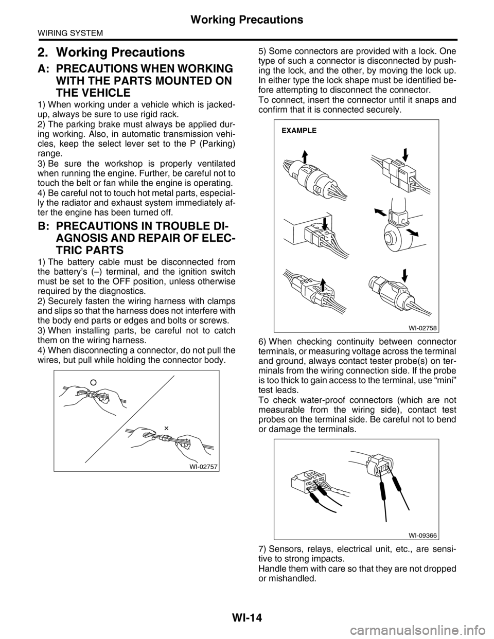
5) Some connectors are provided with a lock. One
type of such a connector is disconnected by push-
ing the lock, and the other, by moving the lock up.
In either type the lock shape must be identified be-
fore attempting to disconnect the connector.
To connect, insert the connector until it snaps and
confirm that it is connected securely.
6) When checking continuity between connector
terminals, or measuring voltage across the terminal
and ground, always contact tester probe(s) on ter-
minals from the wiring connection side. If the probe
is too thick to gain access to the terminal, use “mini”
test leads.
To check water-proof connectors (which are not
measurable from the wiring side), contact test
probes on the terminal side. Be careful not to bend
or damage the terminals.
7) Sensors, relays, electrical unit, etc., are sensi-
tive to strong impacts.
Handle them with care so that they are not dropped
or mishandled.
WI-02757
WI-02758
EXAMPLE
WI-09366
Page 2307 of 2453
WI-23
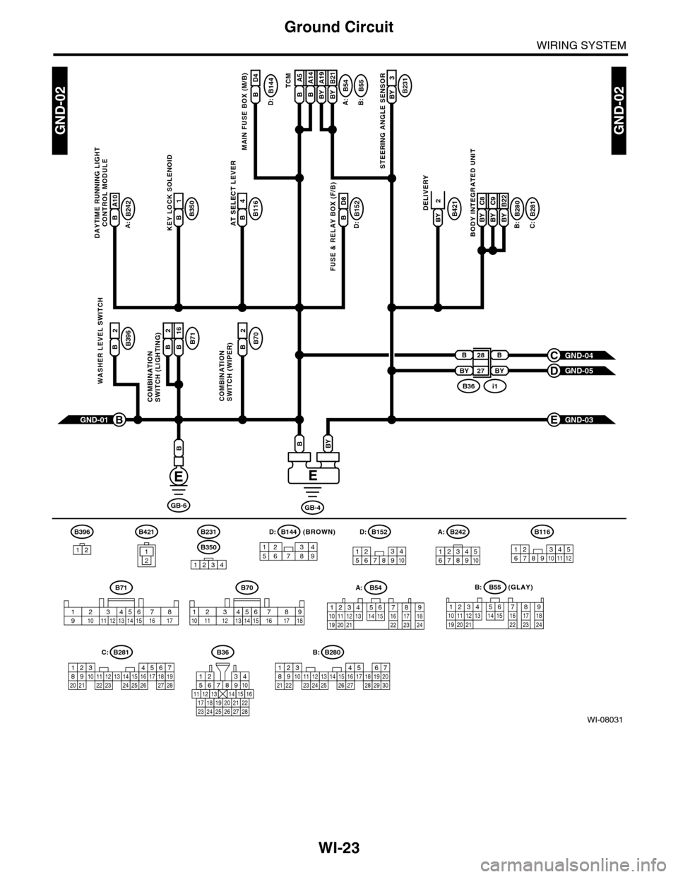
Ground Circuit
WIRING SYSTEM
WI-08031
GND-02GND-02
GB-6
B28
BY
B
BY 27
GND-01B
B
GB-4
BYB
B144B
MAIN FUSE BOX (M/B)
A:
B116B4AT SELECT LEVER
B54
A:
B242
B:
B:C:D:
B55B A5B A14BY A19BY B21TCMB231BY 3
STEERING ANGLE SENSOR
B350B1KEY LOCK SOLENOID
B152B D8
FUSE & RELAY BOX (F/B)
B421BY
DELIVERY
B71B2B 16
COMBINATIONSWITCH (LIGHTING)
B70B2
COMBINATIONSWITCH (WIPER)
B396B2
WASHER LEVEL SWITCH
GND-04C
GND-05D
B280B281BY C8BY C9BY B22
BODY INTEGRATED UNIT
GND-03E
B36i1
D4
D:
B231
B350
1234
B152
12345678910
B70
2364571891112151314 1610 1718
A:B54
A:B242
B:B55
123410 11 1219 20 21135614 1578916 17 1822 23 24
12 7 8 9563410 11 1219 20 2113 14 15 16 17 1822 23 24
567821943102422 23 25111213141526 27 281617181920 21
B281C:
5467821931022 23111213141524 25 26 2716171828 29192021 30
B280B:B36
56782194310
242223 252726 28
11121314151617181920 21
(GLAY)
D:
B71
23456718910 11 12 13 14 15 16 17
B A10
DAYTIME RUNNING LIGHT
CONTROL MODULE
12346789510
B116
123456789101112
B396
1212
B421(BROWN)B144D:
157628349
2
Page 2309 of 2453
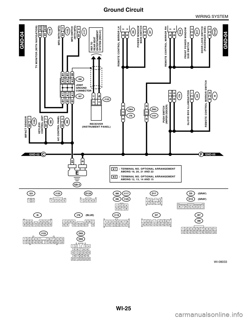
WI-25
Ground Circuit
WIRING SYSTEM
WI-08033
GND-04GND-04
i117BYi122BY 11
8
A/C CONTROL PANEL
i88BY 5
23
GND-05F
KEYLESS CONTROL UNIT
i96BY 7
IMPACT SENSOR
i129BY 7
TV MONITOR (WITH NAVIGATION)
i119BY A15BY A16
GND-02C
GB-3
BBY
D83
MFD (WITH MFD)MFD SWITCH (WITH MFD)
i96
12345678
i6
42
14
REMOTE CONTROL MIRROR SWITCH
i97i133
i98
JOINTGROUNDCONNECTOR
RECEIVER(INSTRUMENT PANEL)
2*2*
1*1*
2*
1*
BYBi231
GLOVE BOX ILLUMINATION
Bi789
PUSH SWITCH(WIPER DEICER)
B
2
BBYBY
SBBYBY
YBr
REF. TOREAR SEATENTERTAINMENT SYSTEM [RES-01]
: TERMINAL NO. OPTIONAL ARRANGEMENT AMONG 19, 20, 21 AND 22
: TERMINAL NO. OPTIONAL ARRANGEMENT AMONG 12, 13, 14 AND 15
1*
2*
D125
5
DOOR LOCK SWITCH(PASSENGER SIDE)
BD17
2
FRONT POWER WINDOW SUB SWITCH
POWER WINDOW
MAIN SWITCH
BD75
BD15
REMOTE CONTROL MIRROR RH
BB
42D5
REMOTE CONTROL MIRROR LH
BB
i1012D83
B
B
i762D84
B
B
D84
i88
i129
i117
567821943
10
2422 23 25
1112131415161718192021
i98
i97
12345678910111213141516171819202122
D7
12345689101112131514716
D17
12345678
D5
D15
87654321
(GRAY)
(GRAY)
i6
12345678910111213141516
i119
123 8910412 13 14 15 1656711
i133
12345
12345678910111213141516171819202122
i122
i78
123456789101112131415
(BLUE)
i23
12
D125
12345
Page 2330 of 2453
WI-46
Engine Electrical System
WIRING SYSTEM
WI-08053
E/G-13E/G-13
123
E31
E34
(BLACK)(BLACK)
RELAY BLOCK
(BLACK)
(BLACK)
E32
E45
(BLACK)
(BLACK)
E33
E46
B21
12345678910 1112 13 14 15 16 17 18 19 2021 2223 24 25 26 27 28 29 30 31 32 33
34 3542 4336 3738 39
48 4950 5152 5354
40 41444546 47
B225
131415 16
17
27
24
2526
20
212223
293031283235
33343738393640
8
91011 12
12
534
761918
B137D:ECM
B21
E2
YG
D19
14
YG
RB
D20
15
GW
WL
D21
16
WL
Or
D22
17
BL
OrB
D23
18
BY
RY
YGRBWLOrOrBRY
D18
13
RY
21
RYWR
IGNITION COIL NO.1IGNITION COIL NO.2IGNITION COIL NO.3IGNITION COIL NO.4IGNITION COIL NO.5IGNITION COIL NO.6
3
LB
21
YGWR
E32E31
3
LB
21
GWWR
E33
3
LB
21
WLWR
E34
3
LB
21
BLWR
E45
3
LB
21
BYWR
E46
3
LB
B225
RELAY HOLDER
15AYR 1GR2E/G-04D
E2
B2149
GR
LB
D:B137
85610 11 12 13 14 157213416
3019 20 2228 29
91718 2521 23 243126 27
E/G-14W
Page 2340 of 2453
WI-56
AT Control System
WIRING SYSTEM
WI-08062
5AT-055AT-05
B280B:
3
B21
B116
B15
RGBY
A19
BY
A14
B
A5
B
B55B:B54A:TCM
ATSELECTLEVERSHIFT LOCKSOLENOID
RG
B6RG
GL
B19
4
B
BYBB
5467821931022 23111213141524 25 26 2716171828 29192021 30
REF. TO GROUNDCIRCUIT [GND-02]REF. TO GROUNDCIRCUIT [GND-02]
C31
C: B136ECM
GL
123410 11 1219 20 21135614 1578916 17 1822 23 24
12 7 8 9563410 11 1219 20 2113 14 15 16 17 1822 23 24
B280B:
BODYINTEGRATEDUNIT
(GRAY)B:B55A:B54B116
123467891011512
C: B136
16101112131415252430
9871718192028212223293231
123456
2726333435