2009 SUBARU TRIBECA lock
[x] Cancel search: lockPage 1012 of 2453
VDC(diag)-20
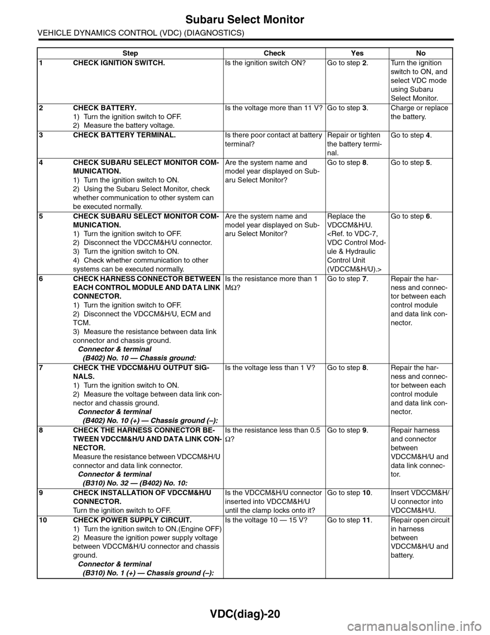
Subaru Select Monitor
VEHICLE DYNAMICS CONTROL (VDC) (DIAGNOSTICS)
Step Check Yes No
1CHECK IGNITION SWITCH.Is the ignition switch ON? Go to step 2.Turn the ignition
switch to ON, and
select VDC mode
using Subaru
Select Monitor.
2CHECK BATTERY.
1) Turn the ignition switch to OFF.
2) Measure the battery voltage.
Is the voltage more than 11 V? Go to step 3.Charge or replace
the battery.
3CHECK BATTERY TERMINAL.Is there poor contact at battery
terminal?
Repair or tighten
the battery termi-
nal.
Go to step 4.
4CHECK SUBARU SELECT MONITOR COM-
MUNICATION.
1) Turn the ignition switch to ON.
2) Using the Subaru Select Monitor, check
whether communication to other system can
be executed normally.
Are the system name and
model year displayed on Sub-
aru Select Monitor?
Go to step 8.Go to step 5.
5CHECK SUBARU SELECT MONITOR COM-
MUNICATION.
1) Turn the ignition switch to OFF.
2) Disconnect the VDCCM&H/U connector.
3) Turn the ignition switch to ON.
4) Check whether communication to other
systems can be executed normally.
Are the system name and
model year displayed on Sub-
aru Select Monitor?
Replace the
VDCCM&H/U.
ule & Hydraulic
Control Unit
(VDCCM&H/U).>
Go to step 6.
6CHECK HARNESS CONNECTOR BETWEEN
EACH CONTROL MODULE AND DATA LINK
CONNECTOR.
1) Turn the ignition switch to OFF.
2) Disconnect the VDCCM&H/U, ECM and
TCM.
3) Measure the resistance between data link
connector and chassis ground.
Connector & terminal
(B402) No. 10 — Chassis ground:
Is the resistance more than 1
MΩ?
Go to step 7.Repair the har-
ness and connec-
tor between each
control module
and data link con-
nector.
7CHECK THE VDCCM&H/U OUTPUT SIG-
NALS.
1) Turn the ignition switch to ON.
2) Measure the voltage between data link con-
nector and chassis ground.
Connector & terminal
(B402) No. 10 (+) — Chassis ground (–):
Is the voltage less than 1 V? Go to step 8.Repair the har-
ness and connec-
tor between each
control module
and data link con-
nector.
8CHECK THE HARNESS CONNECTOR BE-
TWEEN VDCCM&H/U AND DATA LINK CON-
NECTOR.
Measure the resistance between VDCCM&H/U
connector and data link connector.
Connector & terminal
(B310) No. 32 — (B402) No. 10:
Is the resistance less than 0.5
Ω?
Go to step 9.Repair harness
and connector
between
VDCCM&H/U and
data link connec-
tor.
9CHECK INSTALLATION OF VDCCM&H/U
CONNECTOR.
Tu r n t h e i g n i t i o n s w i t c h t o O F F.
Is the VDCCM&H/U connector
inserted into VDCCM&H/U
until the clamp locks onto it?
Go to step 10.Insert VDCCM&H/
U connector into
VDCCM&H/U.
10 CHECK POWER SUPPLY CIRCUIT.
1) Turn the ignition switch to ON.(Engine OFF)
2) Measure the ignition power supply voltage
between VDCCM&H/U connector and chassis
ground.
Connector & terminal
(B310) No. 1 (+) — Chassis ground (–):
Is the voltage 10 — 15 V? Go to step 11.Repair open circuit
in harness
between
VDCCM&H/U and
battery.
Page 1018 of 2453
VDC(diag)-26
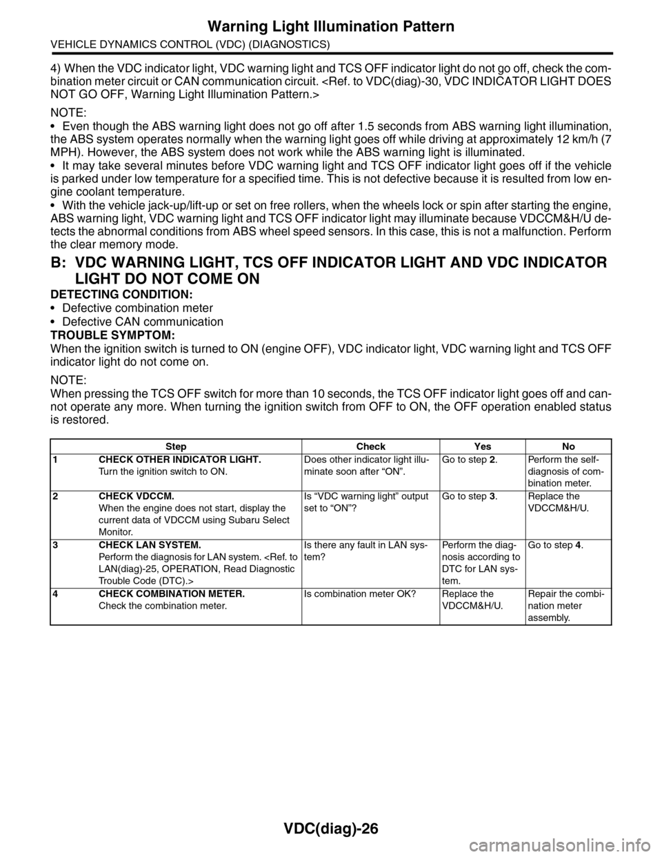
Warning Light Illumination Pattern
VEHICLE DYNAMICS CONTROL (VDC) (DIAGNOSTICS)
4) When the VDC indicator light, VDC warning light and TCS OFF indicator light do not go off, check the com-
bination meter circuit or CAN communication circuit.
NOTE:
•Even though the ABS warning light does not go off after 1.5 seconds from ABS warning light illumination,
the ABS system operates normally when the warning light goes off while driving at approximately 12 km/h (7
MPH). However, the ABS system does not work while the ABS warning light is illuminated.
•It may take several minutes before VDC warning light and TCS OFF indicator light goes off if the vehicle
is parked under low temperature for a specified time. This is not defective because it is resulted from low en-
gine coolant temperature.
•With the vehicle jack-up/lift-up or set on free rollers, when the wheels lock or spin after starting the engine,
ABS warning light, VDC warning light and TCS OFF indicator light may illuminate because VDCCM&H/U de-
tects the abnormal conditions from ABS wheel speed sensors. In this case, this is not a malfunction. Perform
the clear memory mode.
B: VDC WARNING LIGHT, TCS OFF INDICATOR LIGHT AND VDC INDICATOR
LIGHT DO NOT COME ON
DETECTING CONDITION:
•Defective combination meter
•Defective CAN communication
TROUBLE SYMPTOM:
When the ignition switch is turned to ON (engine OFF), VDC indicator light, VDC warning light and TCS OFF
indicator light do not come on.
NOTE:
When pressing the TCS OFF switch for more than 10 seconds, the TCS OFF indicator light goes off and can-
not operate any more. When turning the ignition switch from OFF to ON, the OFF operation enabled status
is restored.
Step Check Yes No
1CHECK OTHER INDICATOR LIGHT.
Tu r n t h e i g n i t i o n s w i t c h t o O N .
Does other indicator light illu-
minate soon after “ON”.
Go to step 2.Perform the self-
diagnosis of com-
bination meter.
2CHECK VDCCM.
When the engine does not start, display the
current data of VDCCM using Subaru Select
Monitor.
Is “VDC warning light” output
set to “ON”?
Go to step 3.Replace the
VDCCM&H/U.
3CHECK LAN SYSTEM.
Perfor m the diagnosis for LAN system.
Tr o u b l e C o d e ( D T C ) . >
Is there any fault in LAN sys-
tem?
Pe r for m t h e d ia g -
nosis according to
DTC for LAN sys-
tem.
Go to step 4.
4CHECK COMBINATION METER.
Check the combination meter.
Is combination meter OK? Replace the
VDCCM&H/U.
Repair the combi-
nation meter
assembly.
Page 1025 of 2453
VDC(diag)-33
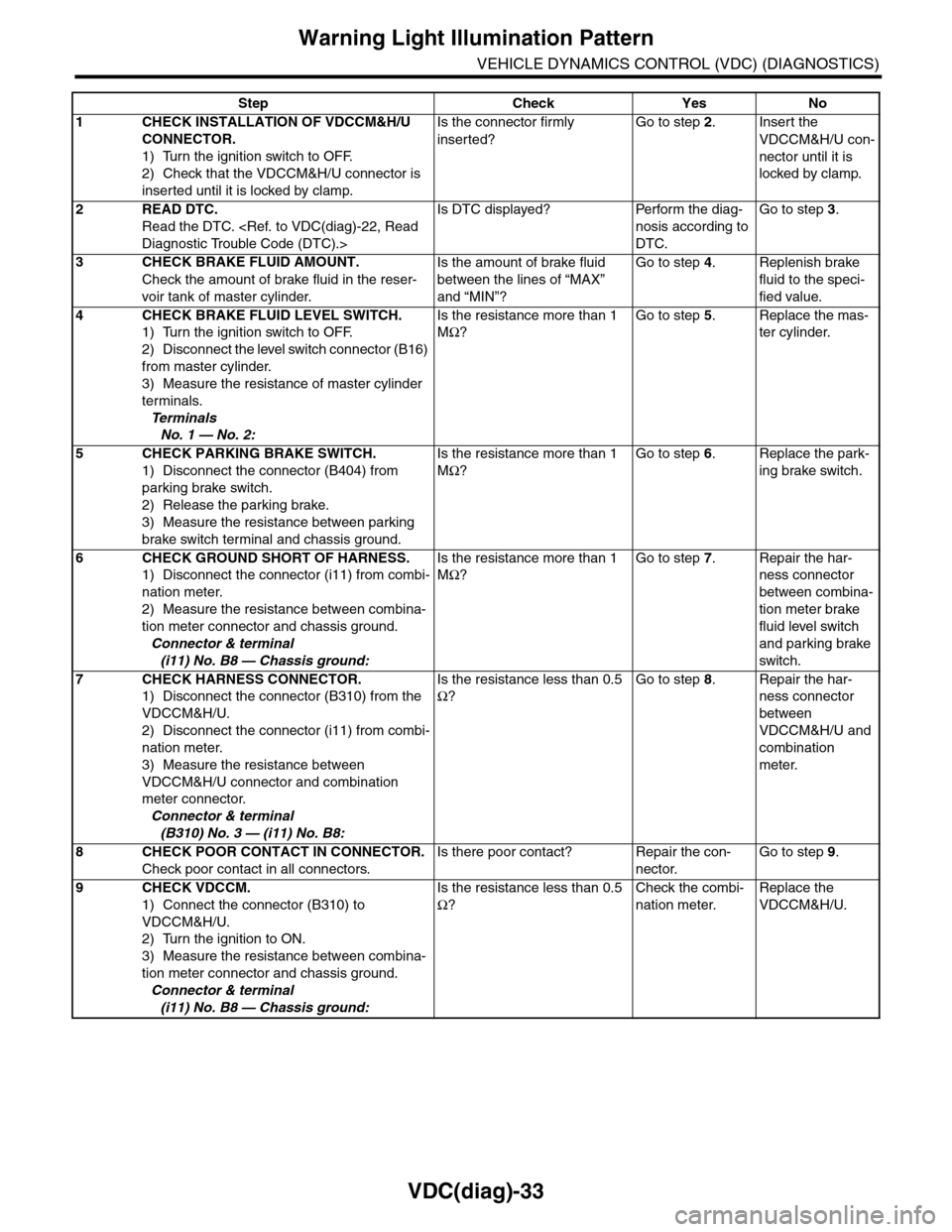
Warning Light Illumination Pattern
VEHICLE DYNAMICS CONTROL (VDC) (DIAGNOSTICS)
Step Check Yes No
1CHECK INSTALLATION OF VDCCM&H/U
CONNECTOR.
1) Turn the ignition switch to OFF.
2) Check that the VDCCM&H/U connector is
inserted until it is locked by clamp.
Is the connector firmly
inserted?
Go to step 2.Insert the
VDCCM&H/U con-
nector until it is
locked by clamp.
2READ DTC.
Read the DTC.
Is DTC displayed? Perform the diag-
nosis according to
DTC.
Go to step 3.
3CHECK BRAKE FLUID AMOUNT.
Check the amount of brake fluid in the reser-
voir tank of master cylinder.
Is the amount of brake fluid
between the lines of “MAX”
and “MIN”?
Go to step 4.Replenish brake
fluid to the speci-
fied value.
4CHECK BRAKE FLUID LEVEL SWITCH.
1) Turn the ignition switch to OFF.
2) Disconnect the level switch connector (B16)
from master cylinder.
3) Measure the resistance of master cylinder
terminals.
Te r m i n a l s
No. 1 — No. 2:
Is the resistance more than 1
MΩ?
Go to step 5.Replace the mas-
ter cylinder.
5CHECK PARKING BRAKE SWITCH.
1) Disconnect the connector (B404) from
parking brake switch.
2) Release the parking brake.
3) Measure the resistance between parking
brake switch terminal and chassis ground.
Is the resistance more than 1
MΩ?
Go to step 6.Replace the park-
ing brake switch.
6CHECK GROUND SHORT OF HARNESS.
1) Disconnect the connector (i11) from combi-
nation meter.
2) Measure the resistance between combina-
tion meter connector and chassis ground.
Connector & terminal
(i11) No. B8 — Chassis ground:
Is the resistance more than 1
MΩ?
Go to step 7.Repair the har-
ness connector
between combina-
tion meter brake
fluid level switch
and parking brake
switch.
7CHECK HARNESS CONNECTOR.
1) Disconnect the connector (B310) from the
VDCCM&H/U.
2) Disconnect the connector (i11) from combi-
nation meter.
3) Measure the resistance between
VDCCM&H/U connector and combination
meter connector.
Connector & terminal
(B310) No. 3 — (i11) No. B8:
Is the resistance less than 0.5
Ω?
Go to step 8.Repair the har-
ness connector
between
VDCCM&H/U and
combination
meter.
8CHECK POOR CONTACT IN CONNECTOR.
Check poor contact in all connectors.
Is there poor contact? Repair the con-
nector.
Go to step 9.
9CHECK VDCCM.
1) Connect the connector (B310) to
VDCCM&H/U.
2) Turn the ignition to ON.
3) Measure the resistance between combina-
tion meter connector and chassis ground.
Connector & terminal
(i11) No. B8 — Chassis ground:
Is the resistance less than 0.5
Ω?
Check the combi-
nation meter.
Replace the
VDCCM&H/U.
Page 1079 of 2453
VDC(diag)-87
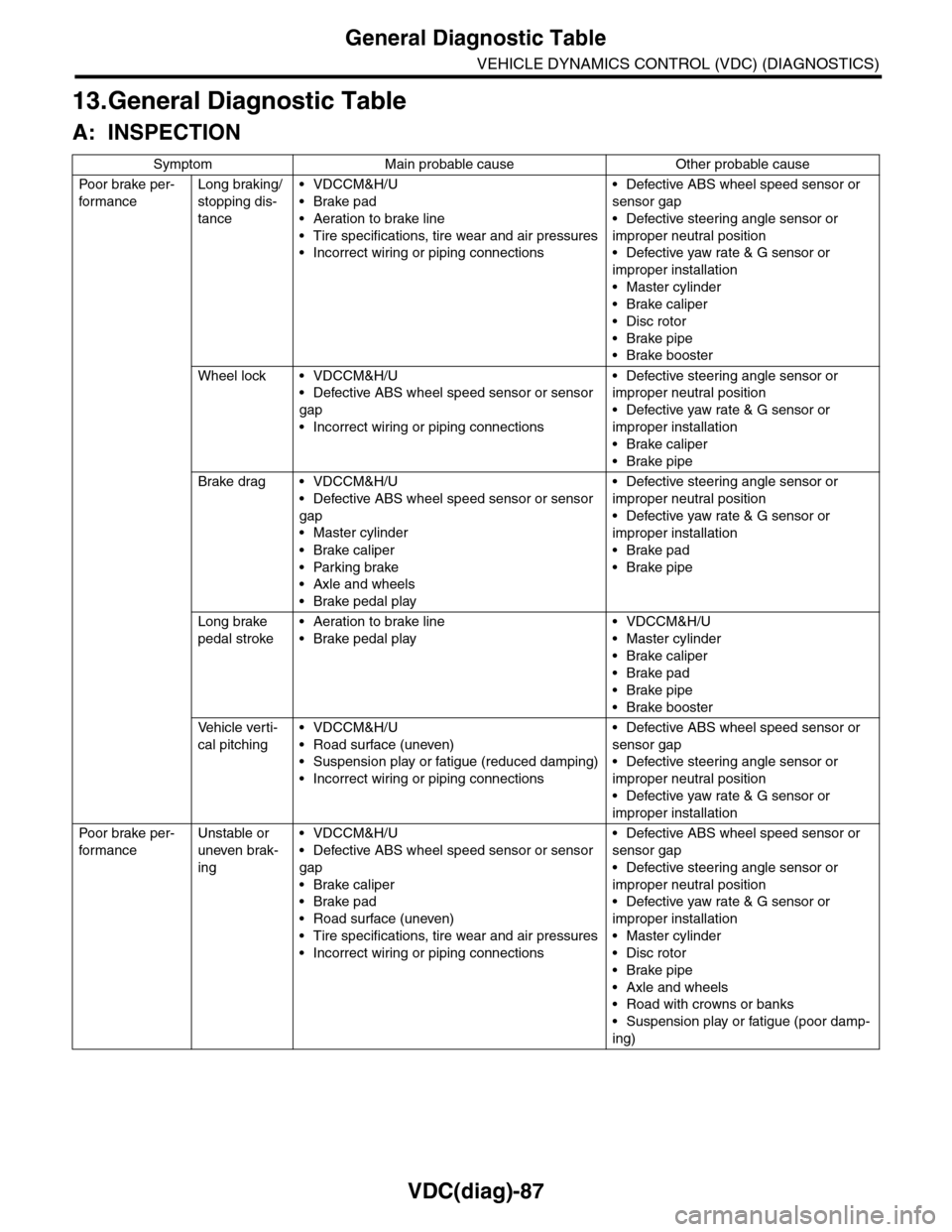
General Diagnostic Table
VEHICLE DYNAMICS CONTROL (VDC) (DIAGNOSTICS)
13.General Diagnostic Table
A: INSPECTION
Symptom Main probable cause Other probable cause
Po or b rake pe r -
for mance
Long braking/
stopping dis-
tance
•VDCCM&H/U
•Brake pad
•Aeration to brake line
•Tire specifications, tire wear and air pressures
•Incorrect wiring or piping connections
•Defective ABS wheel speed sensor or
sensor gap
•Defective steering angle sensor or
improper neutral position
•Defective yaw rate & G sensor or
improper installation
•Master cylinder
•Brake caliper
•Disc rotor
•Brake pipe
•Brake booster
Wheel lock • VDCCM&H/U
•Defective ABS wheel speed sensor or sensor
gap
•Incorrect wiring or piping connections
•Defective steering angle sensor or
improper neutral position
•Defective yaw rate & G sensor or
improper installation
•Brake caliper
•Brake pipe
Brake drag • VDCCM&H/U
•Defective ABS wheel speed sensor or sensor
gap
•Master cylinder
•Brake caliper
•Parking brake
•Axle and wheels
•Brake pedal play
•Defective steering angle sensor or
improper neutral position
•Defective yaw rate & G sensor or
improper installation
•Brake pad
•Brake pipe
Long brake
pedal stroke
•Aeration to brake line
•Brake pedal play
•VDCCM&H/U
•Master cylinder
•Brake caliper
•Brake pad
•Brake pipe
•Brake booster
Ve h i c l e v e r t i -
cal pitching
•VDCCM&H/U
•Road surface (uneven)
•Suspension play or fatigue (reduced damping)
•Incorrect wiring or piping connections
•Defective ABS wheel speed sensor or
sensor gap
•Defective steering angle sensor or
improper neutral position
•Defective yaw rate & G sensor or
improper installation
Po or b rake pe r -
for mance
Unstable or
uneven brak-
ing
•VDCCM&H/U
•Defective ABS wheel speed sensor or sensor
gap
•Brake caliper
•Brake pad
•Road surface (uneven)
•Tire specifications, tire wear and air pressures
•Incorrect wiring or piping connections
•Defective ABS wheel speed sensor or
sensor gap
•Defective steering angle sensor or
improper neutral position
•Defective yaw rate & G sensor or
improper installation
•Master cylinder
•Disc rotor
•Brake pipe
•Axle and wheels
•Road with crowns or banks
•Suspension play or fatigue (poor damp-
ing)
Page 1088 of 2453
VDC-7
VDC Control Module & Hydraulic Control Unit (VDCCM&H/U)
VEHICLE DYNAMICS CONTROL (VDC)
2. VDC Control Module & Hy-
draulic Control Unit (VDC-
CM&H/U)
A: REMOVAL
1) Disconnect the ground cable from the battery.
2) Use compressed air to remove moisture and
dust around the VDCCM&H/U.
NOTE:
If the terminals become dirty, it may cause improp-
er contact.
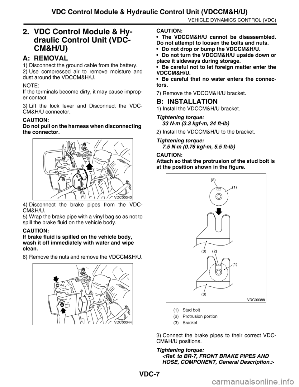
3) Lift the lock lever and Disconnect the VDC-
CM&H/U connector.
CAUTION:
Do not pull on the harness when disconnecting
the connector.
4) Disconnect the brake pipes from the VDC-
CM&H/U.
5) Wrap the brake pipe with a vinyl bag so as not to
spill the brake fluid on the vehicle body.
CAUTION:
If brake fluid is spilled on the vehicle body,
wash it off immediately with water and wipe
clean.
6) Remove the nuts and remove the VDCCM&H/U.
CAUTION:
•The VDCCM&H/U cannot be disassembled.
Do not attempt to loosen the bolts and nuts.
•Do not drop or bump the VDCCM&H/U.
•Do not turn the VDCCM&H/U upside down or
place it sideways during storage.
•Be careful not to let foreign matter enter the
VDCCM&H/U.
•Be careful that no water enters the connec-
tors.
7) Remove the VDCCM&H/U bracket.
B: INSTALLATION
1) Install the VDCCM&H/U bracket.
Tightening torque:
33 N·m (3.3 kgf-m, 24 ft-lb)
2) Install the VDCCM&H/U to the bracket.
Tightening torque:
7.5 N·m (0.76 kgf-m, 5.5 ft-lb)
CAUTION:
Attach so that the protrusion of the stud bolt is
at the position shown in the figure.
3) Connect the brake pipes to their correct VDC-
CM&H/U positions.
Tightening torque:
VDC00343
VDC00344
(1) Stud bolt
(2) Protrusion por tion
(3) Bracket
Page 1089 of 2453
VDC-8
VDC Control Module & Hydraulic Control Unit (VDCCM&H/U)
VEHICLE DYNAMICS CONTROL (VDC)
4) Connect the VDCCM&H/U connectors.
NOTE:
•Be sure to remove all foreign matter from inside
the connector before connecting.
•Make sure the VDCCM&H/U connector is se-
curely locked.
5) Bleed air from the brake system.
C: INSPECTION
1) Check the condition of connection and settle-
ment of connector.
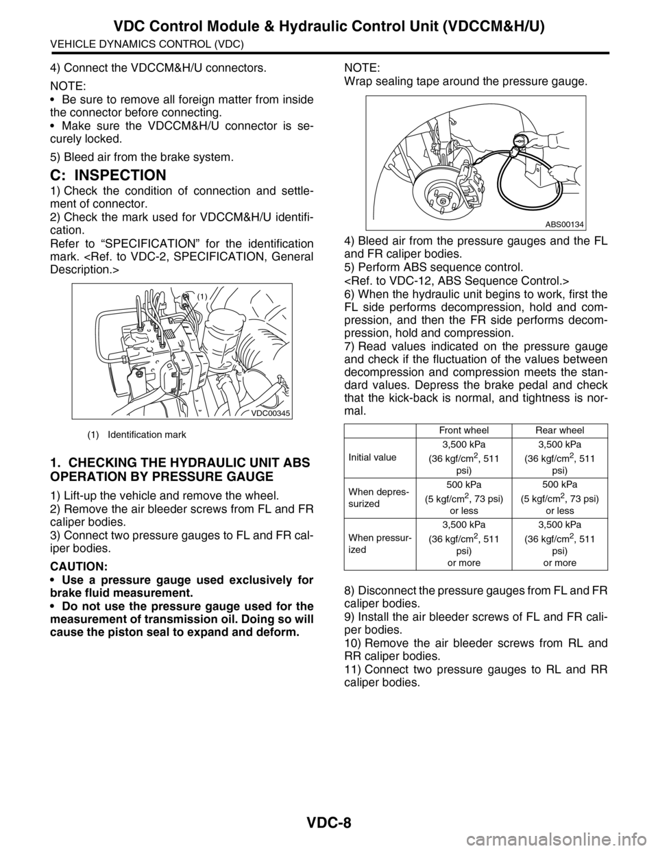
2) Check the mark used for VDCCM&H/U identifi-
cation.
Refer to “SPECIFICATION” for the identification
mark.
1. CHECKING THE HYDRAULIC UNIT ABS
OPERATION BY PRESSURE GAUGE
1) Lift-up the vehicle and remove the wheel.
2) Remove the air bleeder screws from FL and FR
caliper bodies.
3) Connect two pressure gauges to FL and FR cal-
iper bodies.
CAUTION:
•Use a pressure gauge used exclusively for
brake fluid measurement.
•Do not use the pressure gauge used for the
measurement of transmission oil. Doing so will
cause the piston seal to expand and deform.
NOTE:
Wrap sealing tape around the pressure gauge.
4) Bleed air from the pressure gauges and the FL
and FR caliper bodies.
5) Perform ABS sequence control.
6) When the hydraulic unit begins to work, first the
FL side performs decompression, hold and com-
pression, and then the FR side performs decom-
pression, hold and compression.
7) Read values indicated on the pressure gauge
and check if the fluctuation of the values between
decompression and compression meets the stan-
dard values. Depress the brake pedal and check
that the kick-back is normal, and tightness is nor-
mal.
8) Disconnect the pressure gauges from FL and FR
caliper bodies.
9) Install the air bleeder screws of FL and FR cali-
per bodies.
10) Remove the air bleeder screws from RL and
RR caliper bodies.
11) Connect two pressure gauges to RL and RR
caliper bodies.
(1) Identification mark
VDC00345
(1)
Front wheelRear wheel
Initial value
3,500 kPa
(36 kgf/cm2, 511
psi)
3,500 kPa
(36 kgf/cm2, 511
psi)
When depres-
surized
500 kPa
(5 kgf/cm2, 73 psi)
or less
500 kPa
(5 kgf/cm2, 73 psi)
or less
When pressur-
ized
3,500 kPa
(36 kgf/cm2, 511
psi)
or more
3,500 kPa
(36 kgf/cm2, 511
psi)
or more
ABS00134
Page 1100 of 2453
VDC-19
Steering Angle Sensor
VEHICLE DYNAMICS CONTROL (VDC)
6. Steering Angle Sensor
A: REPLACEMENT
CAUTION:
•Do not perform the removal except when the
replacement.
•When replacing more than three times, re-
place the combination switch as assembly to
protect the threads.
1) Set the steering wheel in a straight-ahead posi-
tion.
2) Disconnect the ground cable from the battery.
3) Remove the airbag module.
WARNING:
Always refer to “Airbag System” when perform-
ing the airbag module repair service.
4) Remove the steering wheel.
5) Remove the screws and remove the steering
column lower cover.
6) Remove the two screws securing the steering
column upper cover.
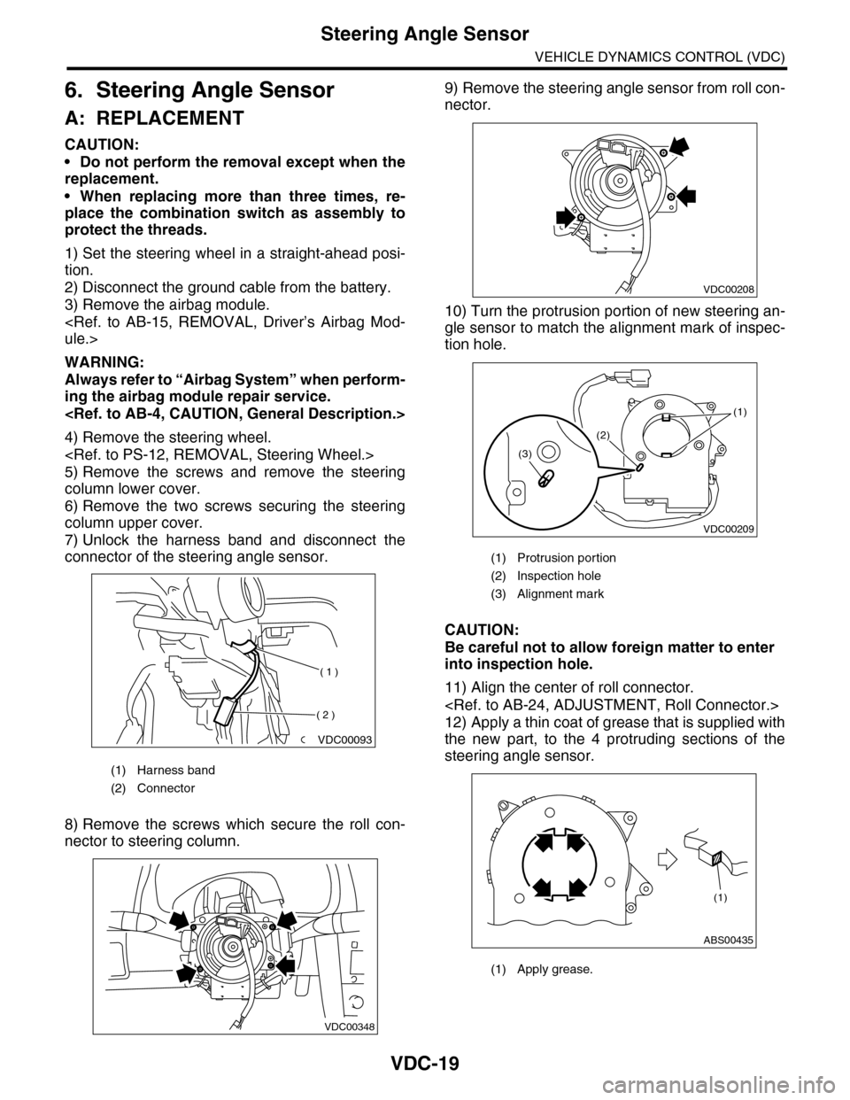
7) Unlock the harness band and disconnect the
connector of the steering angle sensor.
8) Remove the screws which secure the roll con-
nector to steering column.
9) Remove the steering angle sensor from roll con-
nector.
10) Turn the protrusion portion of new steering an-
gle sensor to match the alignment mark of inspec-
tion hole.
CAUTION:
Be careful not to allow foreign matter to enter
into inspection hole.
11) Align the center of roll connector.
12) Apply a thin coat of grease that is supplied with
the new part, to the 4 protruding sections of the
steering angle sensor.
(1) Harness band
(2) Connector
VDC00093
( 1 )
( 2 )
VDC00348
(1) Protrusion portion
(2) Inspection hole
(3) Alignment mark
(1) Apply grease.
VDC00208
VDC00209
(1)
(2)
(3)
ABS00435
(1)
Page 1198 of 2453
EN(H6DO)(diag)-37
Inspection Mode
ENGINE (DIAGNOSTICS)
1. PREPARATION FOR THE INSPECTION
MODE
1) Check battery voltage is more than 12 V and fuel
remains half [20 to 40 2 (5.3 to 10.6 US gal, 4.4 to
8.8 Imp gal)].
2) Lift-up the vehicle using a garage jack and place
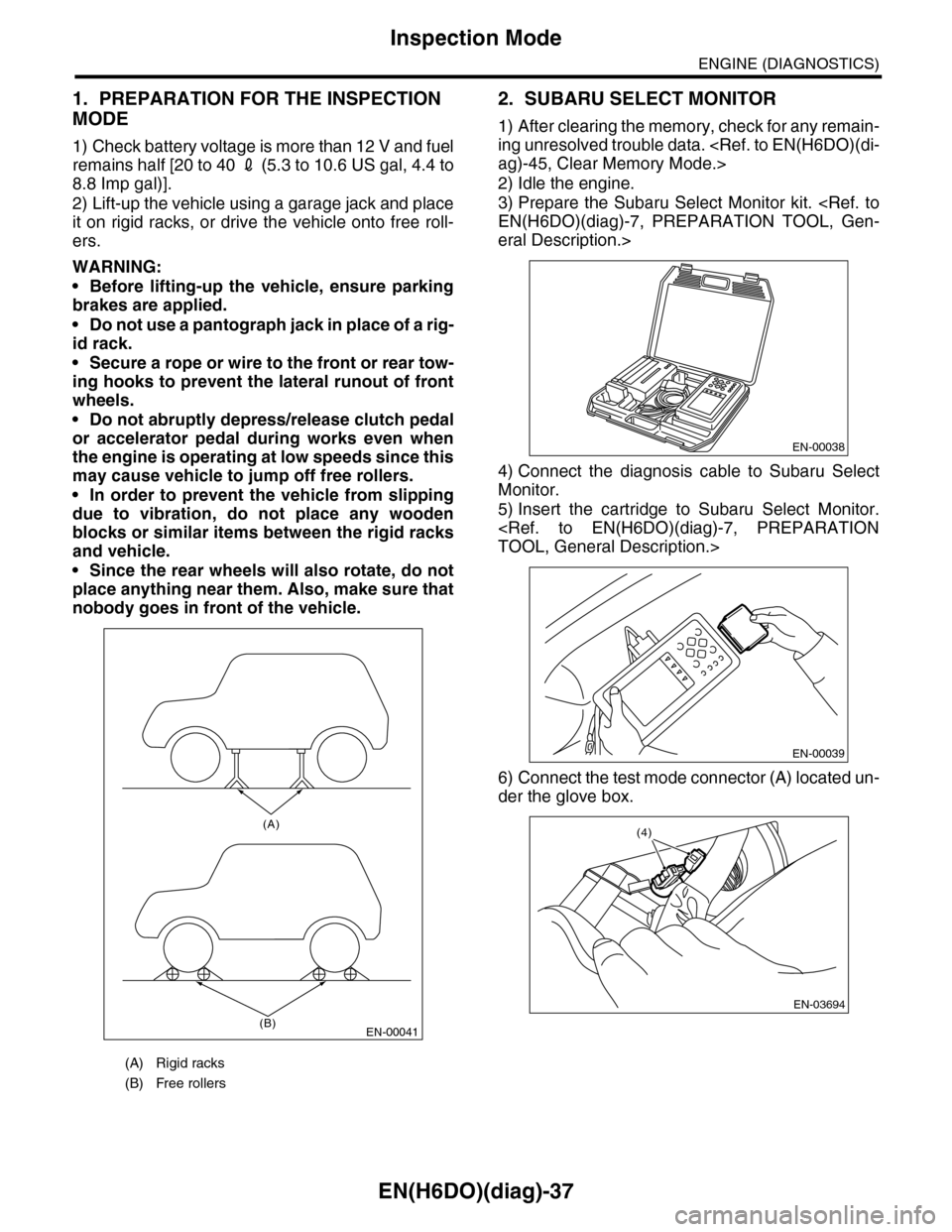
it on rigid racks, or drive the vehicle onto free roll-
ers.
WARNING:
•Before lifting-up the vehicle, ensure parking
brakes are applied.
•Do not use a pantograph jack in place of a rig-
id rack.
•Secure a rope or wire to the front or rear tow-
ing hooks to prevent the lateral runout of front
wheels.
•Do not abruptly depress/release clutch pedal
or accelerator pedal during works even when
the engine is operating at low speeds since this
may cause vehicle to jump off free rollers.
•In order to prevent the vehicle from slipping
due to vibration, do not place any wooden
blocks or similar items between the rigid racks
and vehicle.
•Since the rear wheels will also rotate, do not
place anything near them. Also, make sure that
nobody goes in front of the vehicle.
2. SUBARU SELECT MONITOR
1) After clearing the memory, check for any remain-
ing unresolved trouble data.
2) Idle the engine.
3) Prepare the Subaru Select Monitor kit.
eral Description.>
4) Connect the diagnosis cable to Subaru Select
Monitor.
5) Insert the cartridge to Subaru Select Monitor.
6) Connect the test mode connector (A) located un-
der the glove box.
(A) Rigid racks
(B) Free rollers
EN-00041
(A)
(B)
EN-00038
EN-00039
EN-03694
(4)