Page 18 of 2453

AB-19
Curtain Airbag Module
AIRBAG SYSTEM
7. Curtain Airbag Module
A: REMOVAL
CAUTION:
Refer to “CAUTION” of “General Description”
before handling the airbag module.
4, CAUTION, General Description.>
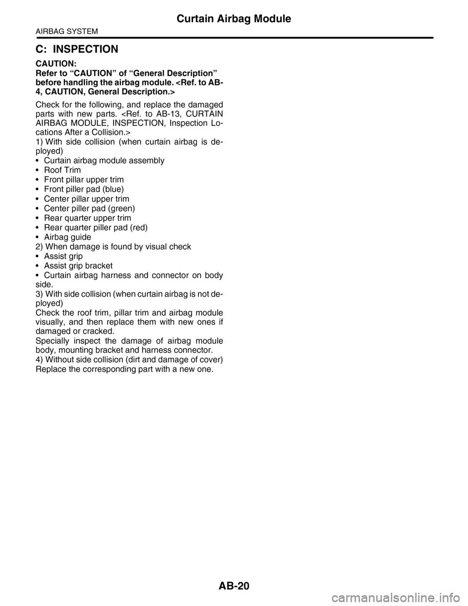
1) Turn the ignition switch to OFF.
2) Disconnect the ground cable from battery and
wait for at least 20 seconds before starting work.
3) Remove the front pillar upper trim and center pil-
lar upper trim.
PER TRIM, REMOVAL, Side Trim.>
CENTER PILLAR UPPER TRIM, REMOVAL, Side
Trim.>
4) Remove the rear quarter trim.
REMOVAL, Rear Quarter Trim.>
5) Remove the roof trim.
AL, Roof Trim.>
6) Disconnect the curtain airbag module connector.
7) Remove the bolts, and then remove the curtain
airbag module.
CAUTION:
•Be careful not to damage the curtain airbag
module during removal.
•Never open the curtain airbag module before
deploying it. Never reuse the deployed curtain
airbag module.
8) Remove the front piller from front pillar pad.
B: INSTALLATION
CAUTION:
•Refer to “CAUTION” of “General Description”
before handling the airbag module.
4, CAUTION, General Description.>
•When installing the curtain airbag module, in-
stall a specified part at specified place.
•Be careful not to damage the curtain airbag
module during removal.
•Never open the curtain airbag module before
deploying it. Never reuse the deployed curtain
airbag module.
•Make sure that there are no foreign matter on
airbag module.
Install in the reverse order of removal.
Tightening torque:
7.5 N·m (0.77 kgf-m, 5.5 ft-lb)
AB-01277
AB-01278
AB-01279
Page 19 of 2453

AB-20
Curtain Airbag Module
AIRBAG SYSTEM
C: INSPECTION
CAUTION:
Refer to “CAUTION” of “General Description”
before handling the airbag module.
4, CAUTION, General Description.>
Check for the following, and replace the damaged
parts with new parts.
AIRBAG MODULE, INSPECTION, Inspection Lo-
cations After a Collision.>
1) With side collision (when curtain airbag is de-
ployed)
•Curtain airbag module assembly
•Roof Trim
•Front pillar upper trim
•Front piller pad (blue)
•Center pillar upper trim
•Center piller pad (green)
•Rear quarter upper trim
•Rear quarter piller pad (red)
•Airbag guide
2) When damage is found by visual check
•Assist grip
•Assist grip bracket
•Curtain airbag harness and connector on body
side.
3) With side collision (when curtain airbag is not de-
ployed)
Check the roof trim, pillar trim and airbag module
visually, and then replace them with new ones if
damaged or cracked.
Specially inspect the damage of airbag module
body, mounting bracket and harness connector.
4) Without side collision (dirt and damage of cover)
Replace the corresponding part with a new one.
Page 213 of 2453

ET-28
Rear Entertainment
ENTERTAINMENT
23.Rear Entertainment
A: REMOVAL
1) Disconnect the ground cable from battery.
2) Insert a flat tip screw driver in the section, and
remove the room lamp lens.
3) Remove the bolts, and then remove the monitor
cover.
4) Remove the 4 mounting bolts.
5) Remove the temporary screws and remove the
monitor body.
NOTE:
Always support with one hand to prevent the unit
from falling.
6) Remove the temporary clips from the roof brace.
B: INSTALLATION
1) Attach the temporary clip and temporary screw
to the rear entertainment system body.
NOTE:
When installing a new rear entertainment system, a
clip is supplied on the unit, and this step can be
omitted.
2) Place the hook of the rear entertainment unit on
the roof brace section.
3) Affix the temporary fixture clips on the roof
brace.
4) Tighten the 4 attachment bolts, and connect the
connector.
5) Connect the room lamp connector, attach the
cover and affix with the bolts.
6) Attach the room lamp lens from the outside of
the vehicle and snap into place.
Install in the reverse order of removal.
(A) Cutout
(A) Clip
ET-00188
(A)
ET-00189
(A)
ET-00199
ET-00190
Page 223 of 2453

EB-4
General Description
EXTERIOR BODY PANELS
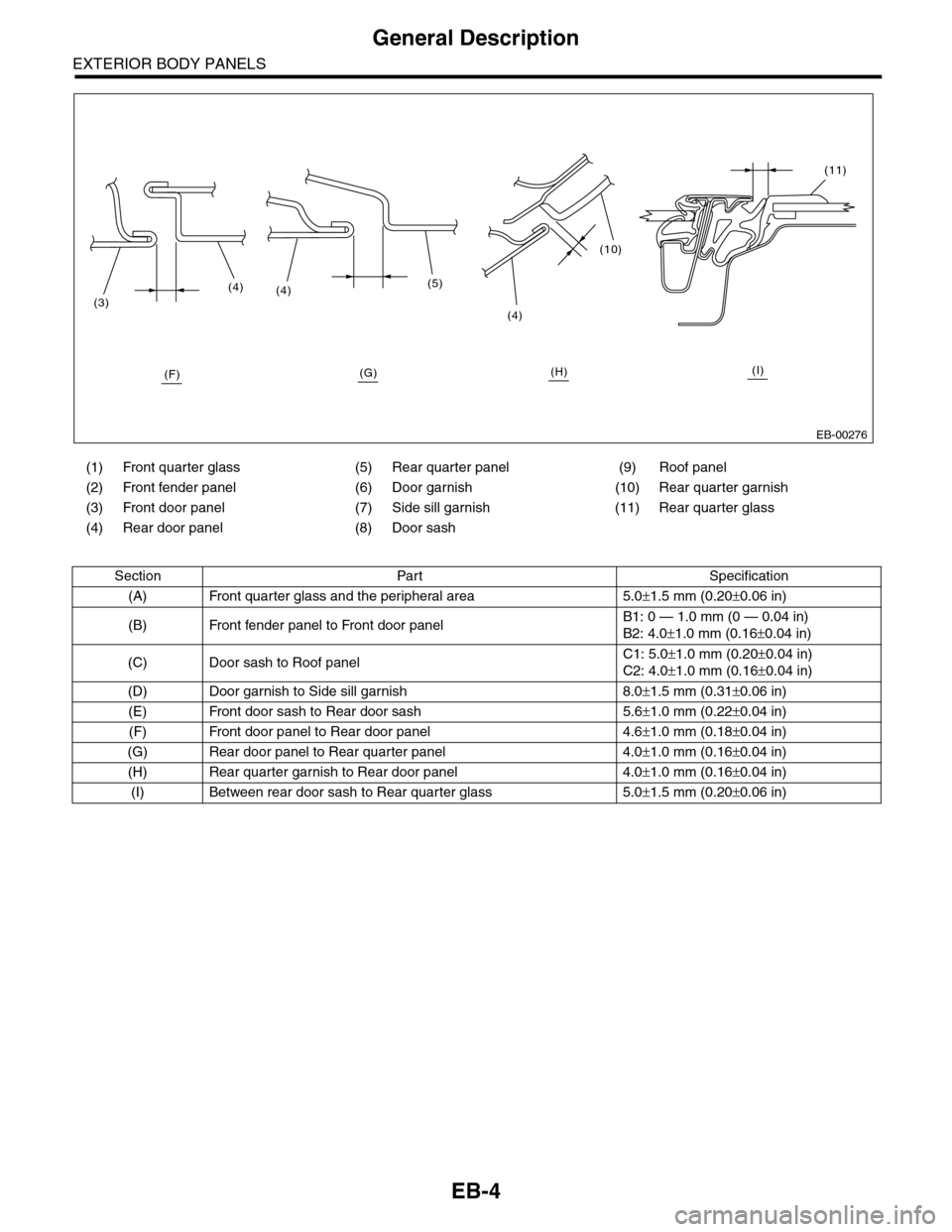
(1) Front quarter glass (5) Rear quarter panel (9) Roof panel
(2) Front fender panel (6) Door garnish (10) Rear quarter garnish
(3) Front door panel (7) Side sill garnish (11) Rear quarter glass
(4) Rear door panel (8) Door sash
Section Part Specification
(A) Front quarter glass and the peripheral area 5.0±1.5 mm (0.20±0.06 in)
(B) Front fender panel to Front door panelB1: 0 — 1.0 mm (0 — 0.04 in)
B2: 4.0±1.0 mm (0.16±0.04 in)
(C) Door sash to Roof panelC1: 5.0±1.0 mm (0.20±0.04 in)
C2: 4.0±1.0 mm (0.16±0.04 in)
(D) Door garnish to Side sill garnish 8.0±1.5 mm (0.31±0.06 in)
(E) Front door sash to Rear door sash 5.6±1.0 mm (0.22±0.04 in)
(F) Front door panel to Rear door panel 4.6±1.0 mm (0.18±0.04 in)
(G) Rear door panel to Rear quarter panel 4.0±1.0 mm (0.16±0.04 in)
(H) Rear quarter garnish to Rear door panel 4.0±1.0 mm (0.16±0.04 in)
(I) Between rear door sash to Rear quarter glass 5.0±1.5 mm (0.20±0.06 in)
EB-00276
(3)
(4)(4)(5)
(4)
(10)
(11)
(F)(G)(H)(I)
Page 225 of 2453

EB-6
General Description
EXTERIOR BODY PANELS
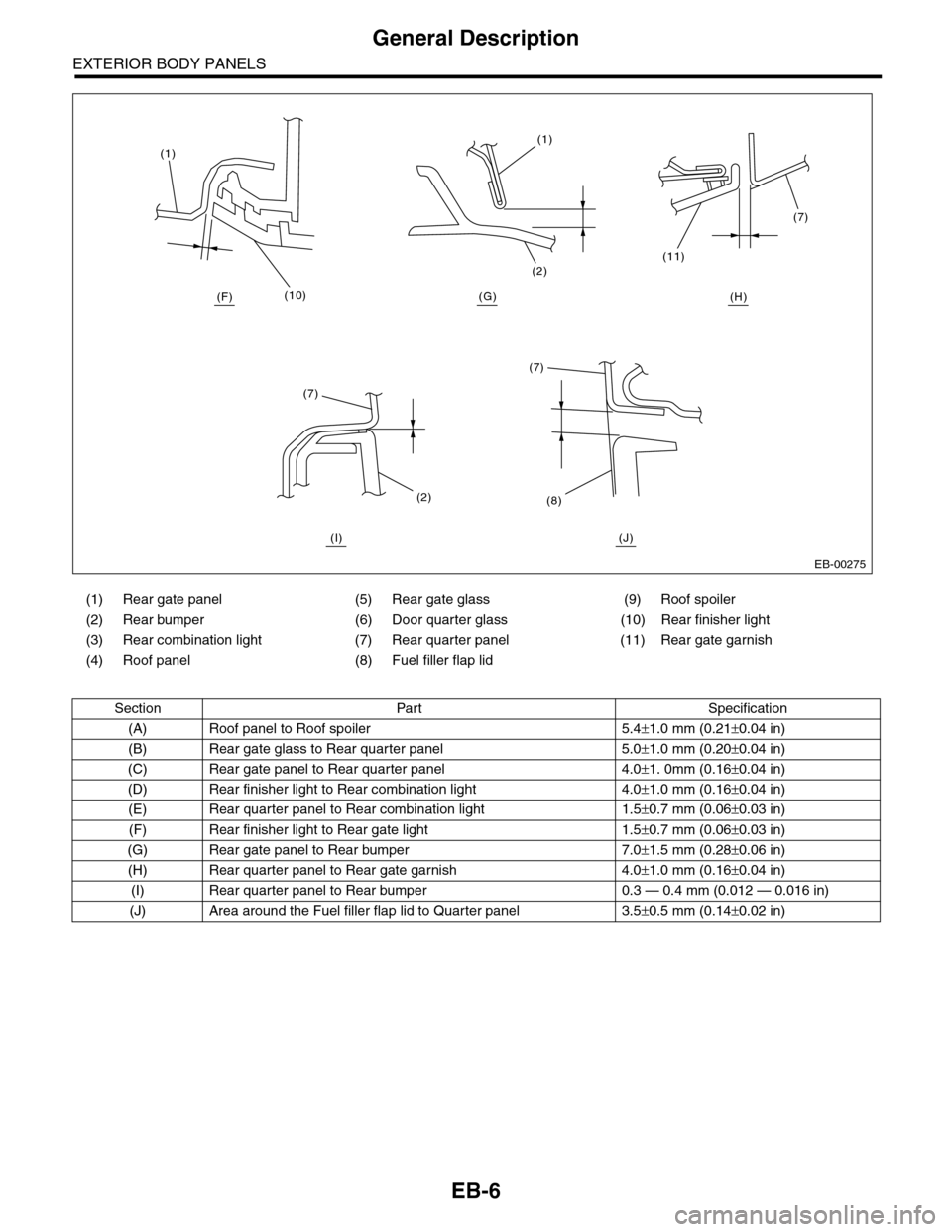
(1) Rear gate panel (5) Rear gate glass (9) Roof spoiler
(2) Rear bumper (6) Door quarter glass (10) Rear finisher light
(3) Rear combination light (7) Rear quarter panel (11) Rear gate garnish
(4) Roof panel (8) Fuel filler flap lid
Section Part Specification
(A) Roof panel to Roof spoiler 5.4±1.0 mm (0.21±0.04 in)
(B) Rear gate glass to Rear quarter panel 5.0±1.0 mm (0.20±0.04 in)
(C) Rear gate panel to Rear quarter panel 4.0±1. 0mm (0.16±0.04 in)
(D) Rear finisher light to Rear combination light 4.0±1.0 mm (0.16±0.04 in)
(E) Rear quarter panel to Rear combination light 1.5±0.7 mm (0.06±0.03 in)
(F) Rear finisher light to Rear gate light 1.5±0.7 mm (0.06±0.03 in)
(G) Rear gate panel to Rear bumper 7.0±1.5 mm (0.28±0.06 in)
(H) Rear quarter panel to Rear gate garnish 4.0±1.0 mm (0.16±0.04 in)
(I) Rear quarter panel to Rear bumper 0.3 — 0.4 mm (0.012 — 0.016 in)
(J) Area around the Fuel filler flap lid to Quarter panel 3.5±0.5 mm (0.14±0.02 in)
EB-00275
(10)
(1)(1)
(2)
(7)
(11)
(7)
(8)(2)
(7)
(H)(G)(F)
(I) (J)
Page 241 of 2453

EB-22
Rear Gate
EXTERIOR BODY PANELS
8. Rear Gate
A: REMOVAL
1. REAR GATE PANEL
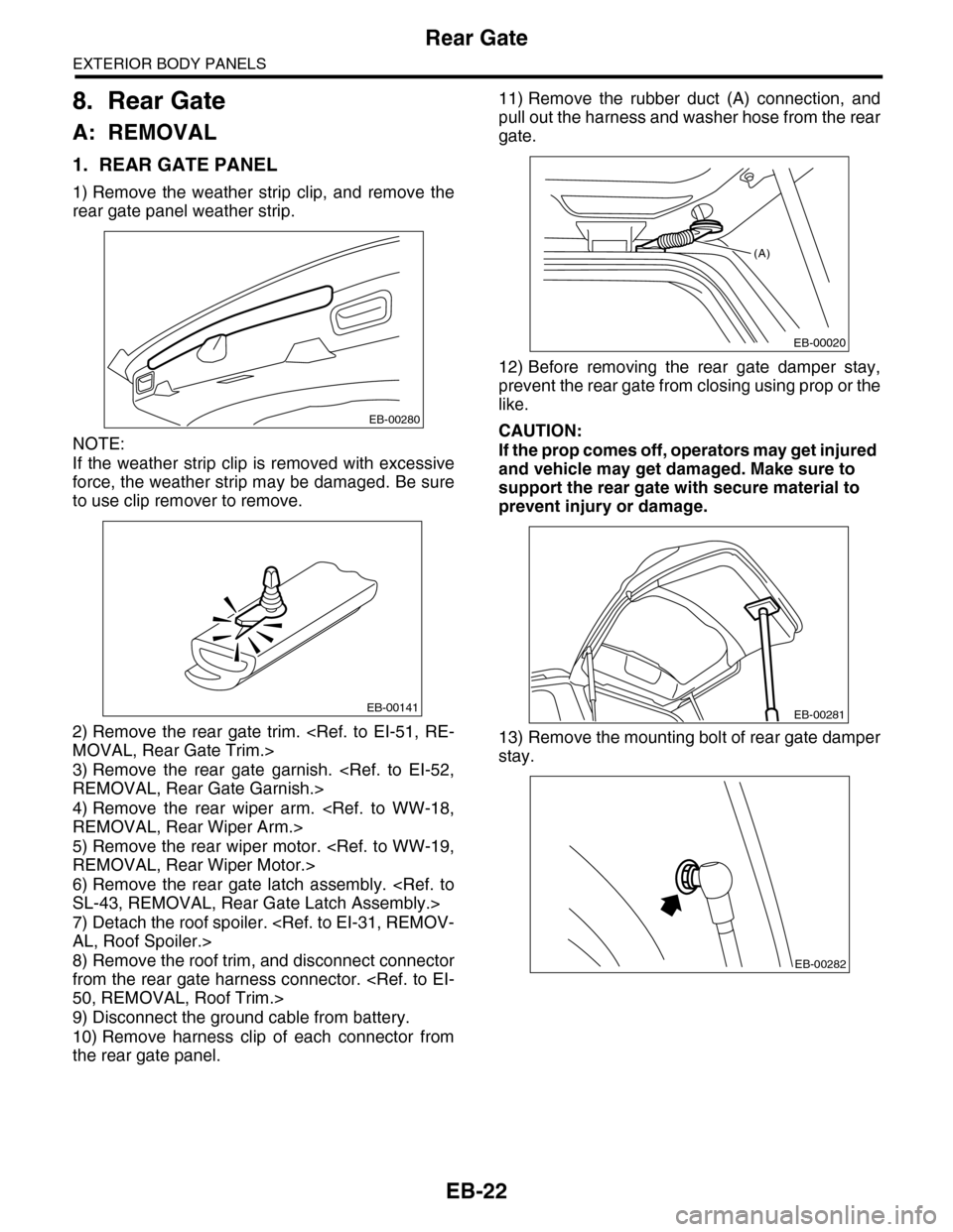
1) Remove the weather strip clip, and remove the
rear gate panel weather strip.
NOTE:
If the weather strip clip is removed with excessive
force, the weather strip may be damaged. Be sure
to use clip remover to remove.
2) Remove the rear gate trim.
MOVAL, Rear Gate Trim.>
3) Remove the rear gate garnish.
REMOVAL, Rear Gate Garnish.>
4) Remove the rear wiper arm.
REMOVAL, Rear Wiper Arm.>
5) Remove the rear wiper motor.
REMOVAL, Rear Wiper Motor.>
6) Remove the rear gate latch assembly.
SL-43, REMOVAL, Rear Gate Latch Assembly.>
7) Detach the roof spoiler.
AL, Roof Spoiler.>
8) Remove the roof trim, and disconnect connector
from the rear gate harness connector.
50, REMOVAL, Roof Trim.>
9) Disconnect the ground cable from battery.
10) Remove harness clip of each connector from
the rear gate panel.
11) Remove the rubber duct (A) connection, and
pull out the harness and washer hose from the rear
gate.
12) Before removing the rear gate damper stay,
prevent the rear gate from closing using prop or the
like.
CAUTION:
If the prop comes off, operators may get injured
and vehicle may get damaged. Make sure to
support the rear gate with secure material to
prevent injury or damage.
13) Remove the mounting bolt of rear gate damper
stay.
EB-00280
EB-00141
(A)
EB-00020
EB-00281
EB-00282
Page 249 of 2453
EI-7
General Description
EXTERIOR/INTERIOR TRIM
7. ROOF SPOILER
(1) Roof spoiler (3) Washer nozzleTightening torque: N·m (kgf-m, ft-lb)
(2) High-mounted stop light T: 4.5 (0.46, 3.32)
EI-01254
T
T
T
(2)
(3)
(1)
Page 250 of 2453
EI-8
General Description
EXTERIOR/INTERIOR TRIM
8. ROOF MOLDING
(1) Roof molding (3) ClipTightening torque: N·m (kgf-m, ft-lb)
(2) Roof carrier attachment (4) RivetT:10 (1.0, 7.23)
EI-01255
T
T(2)
(3)
(4)
(3)
(3)
(1)
(2)