2009 SUBARU TRIBECA lock
[x] Cancel search: lockPage 817 of 2453

DI-33
Rear Differential Front Member
DIFFERENTIALS
7. Rear Differential Front Mem-
ber
A: REMOVAL
1) Disconnect the ground cable from the battery.
2) Jack-up the vehicle.
3) Support the rear differential using transmission
jack, and then remove the rear differential front
member.
B: INSTALLATION
Using new self-locking nuts, install the rear differ-
ential front member.
Tightening torque:
T1: 65 N·m (6.6 kgf-m, 48 ft-lb)
T2: 110 N·m (11.2 kgf-m, 81 ft-lb)
C: INSPECTION
1) Check the rear differential front member for
damage, bend and corrosion.
If damage, bend or corrosion is excessive, replace
the rear differential front member.
2) Check the bushings of rear differential member
for cracking, hardening and damage.
If cracking, hardening or damage is excessive, re-
place rear differential front member.
(A) Rear differential front member
DI-00293(A)
DI-00294
T2
T1
Page 824 of 2453

DS-7
General Description
DRIVE SHAFT SYSTEM
C: CAUTION
Please clearly understand and adhere to the follow-
ing general precautions. They must be strictly fol-
lowed to avoid any injury to the person doing the
work or people in the area.
1. OPERATION
•Wear work clothing, including a cap, protective
goggles and protective shoes during operation.
•Remove contamination including dirt and corro-
sion before removal, installation or disassembly.
•Keep the disassembled parts in order and pro-
tect them from dust and dirt.
•Before removal, installation or disassembly, be
sure to clarify the failure. Avoid unnecessary re-
moval, installation, disassembly and replacement.
•Be careful not to burn yourself, because each
part on the vehicle is hot after running.
•Use SUBARU genuine grease etc. or equivalent.
Do not mix grease etc. with that of another grade or
from other manufacturers.
•Be sure to tighten fasteners including bolts and
nuts to the specified torque.
•Place shop jacks or rigid racks at the specified
points.
• Apply grease onto sliding or revolution surfaces
before installation.
•Before installing snap rings, apply sufficient
amount of grease to avoid damage and deforma-
tion.
•Before securing a part on a vise, place cushion-
ing material such as wood blocks, aluminum plate,
or shop cloth between the part and the vise.
2. OIL
When handling oil, follow the rules below to prevent
unexpected accidents.
•Prepare container and waste cloths when per-
forming work which oil could possibly spill. If oil
spills, wipe it off immediately to prevent from pene-
trating into floor or flowing outside, for environmen-
tal protection.
•Follow all government and local regulations con-
cerning waste disposal.
Page 831 of 2453

DS-14
Front Axle
DRIVE SHAFT SYSTEM
11) Remove the front arm ball joint from the front
housing.
12) Remove the PTJ from transmission.
13) Remove the front drive shaft assembly from the
hub. If it is hard to remove, use the ST.
ST1 926470000 AXLE SHAFT PULLER
ST2 28099PA110 AXLE SHAFT PULLER
PLATE
14) After scribing an alignment mark on the camber
adjusting bolt head, remove the bolts which con-
nect the front housing and strut, and disconnect the
front housing from the strut.
15) Remove the front axle.
B: INSTALLATION
1) Align the alignment mark on the camber adjust-
ing bolt head, and affix the front housing and strut
together using a new selflocking nut.
Tightening torque:
175 N·m (17.9 kgf-m, 129 ft-lb)
2) Install the front drive shaft.
3) Install the front arm ball joint to the front housing.
Tightening torque:
50 N·m (5.1 kgf-m, 36.9 ft-lb)
4) Install the ABS wheel speed sensor on the front
housing.
Tightening torque:
7.5 N·m (0.8 kgf-m, 5.5 ft-lb)
5) Install the disc rotor to hub.
6) Install the disc brake caliper to the front housing.
Tightening torque:
120 N·m (12.2 kgf-m, 88.5 ft-lb)
7) Install the stabilizer link.
8) Connect the tie-rod end ball joint to the knuckle
arm with a castle nut.
Tightening torque:
27.0 N·m (2.75 kgf-m, 19.9 ft-lb)
CAUTION:
When connecting the tie–rod, do not hit the cap
at bottom of tie–rod end with a hammer.
9) Tighten the castle nut to specified torque and
tighten further within 60° until the pin hole is aligned
with the slot in nut. Bend the cotter pin to lock.
FS-00106
DS-00145
ST2
ST1
DS-00356
(A) Cotter pin
(B) Castle nut
(C) Tie–rod
DS-00042
(C)
(B)
(A)
Page 832 of 2453

DS-15
Front Axle
DRIVE SHAFT SYSTEM
10) While depressing the brake pedal, tighten a
new axle nut (olive color) to the specified torque
and lock it securely.
Tightening torque:
240 N·m (24.5 kgf-m, 177 ft-lb)
CAUTION:
•Install the wheel after installation of axle nut.
Failure to follow this rule may damage the
wheel bearing.
•Be sure to tighten the axle nut to specified
torque. Do not overtighten it as this may dam-
age the wheel bearing.
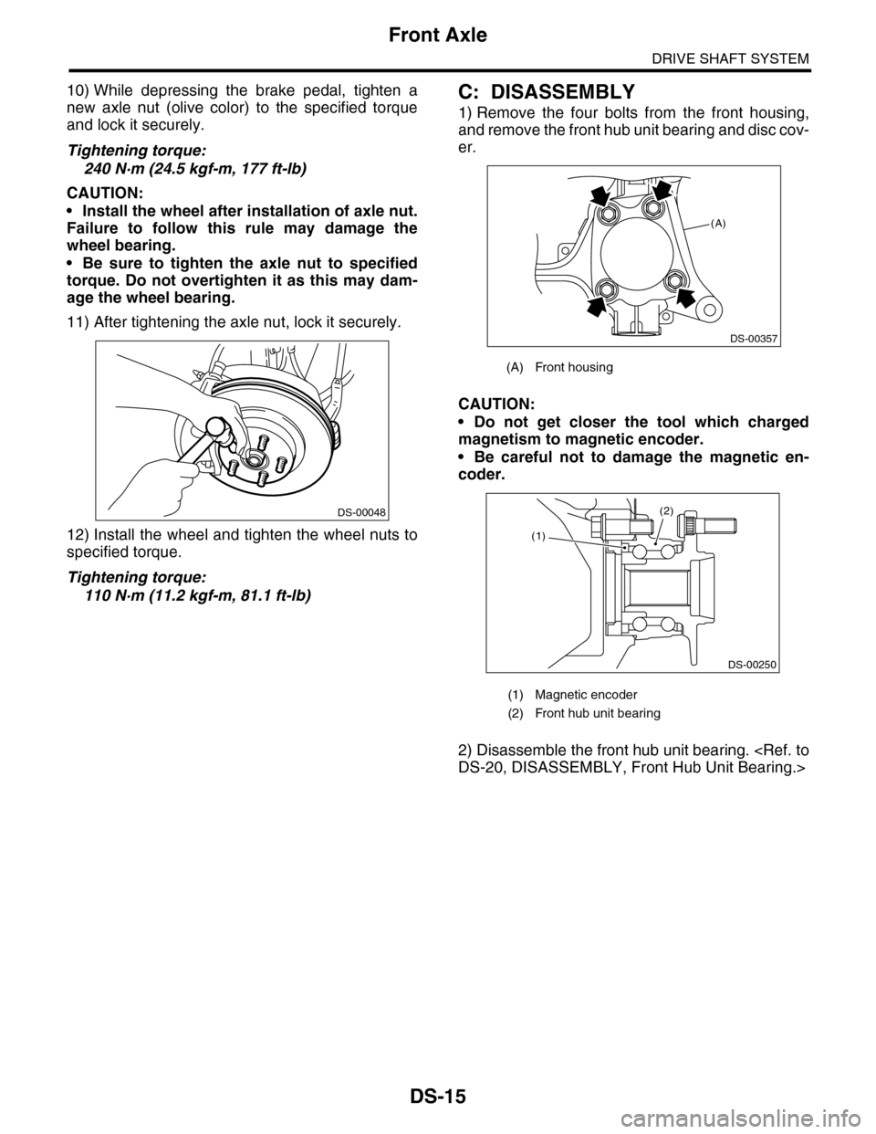
11) After tightening the axle nut, lock it securely.
12) Install the wheel and tighten the wheel nuts to
specified torque.
Tightening torque:
110 N·m (11.2 kgf-m, 81.1 ft-lb)
C: DISASSEMBLY
1) Remove the four bolts from the front housing,
and remove the front hub unit bearing and disc cov-
er.
CAUTION:
•Do not get closer the tool which charged
magnetism to magnetic encoder.
•Be careful not to damage the magnetic en-
coder.
2) Disassemble the front hub unit bearing.
DS-00048
(A) Front housing
(1) Magnetic encoder
(2) Front hub unit bearing
(A)
DS-00357
(2)
DS-00250
(1)
Page 835 of 2453

DS-18
Rear Axle
DRIVE SHAFT SYSTEM
B: INSTALLATION
NOTE:
•Be sure to use a new self-locking nut.
•Always tighten the stabilizer bushing in the state
where the vehicle is at curb weight and the wheels
are in full contact with the ground.
Install in the reverse order of removal.
Tightening torque:
Refer to COMPONENT of General Description
for tightening torque.
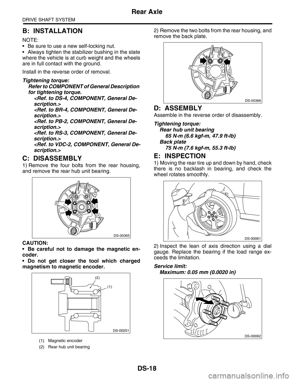
C: DISASSEMBLY
1) Remove the four bolts from the rear housing,
and remove the rear hub unit bearing.
CAUTION:
•Be careful not to damage the magnetic en-
coder.
•Do not get closer the tool which charged
magnetism to magnetic encoder.
2) Remove the two bolts from the rear housing, and
remove the back plate.
D: ASSEMBLY
Assemble in the reverse order of disassembly.
Tightening torque:
Rear hub unit bearing
65 N·m (6.6 kgf-m, 47.9 ft-lb)
Back plate
75 N·m (7.6 kgf-m, 55.3 ft-lb)
E: INSPECTION
1) Moving the rear tire up and down by hand, check
there is no backlash in bearing, and check the
wheel rotates smoothly.
2) Inspect the lean of axis direction using a dial
gauge. Replace the bearing if the load range ex-
ceeds the limitation.
Service limit:
Maximum: 0.05 mm (0.0020 in)
(1) Magnetic encoder
(2) Rear hub unit bearing
DS-00365
DS-00251
(2)
(1)
DS-00366
DS-00061
DS-00062
Page 837 of 2453

DS-20
Front Hub Unit Bearing
DRIVE SHAFT SYSTEM
B: INSTALLATION
1) Place the disc cover between front housing and
front hub unit, and tighten the four bolts.
Tightening torque:
65 N·m (6.6 kgf-m, 47.9 ft-lb)
2) Install the front drive shaft.
3) Tighten the axle nut temporarily.
4) Install the disc rotor to hub.
5) Install the disc brake caliper to the front housing.
Tightening torque:
120 N·m (12.2 kgf-m, 88.5 ft-lb)
6) While depressing the brake pedal, tighten a new
axle nut (olive color) to the specified torque and
lock it securely.
Tightening torque:
240 N·m (24.5 kgf-m, 177 ft-lb)
CAUTION:
•Install the wheel after installation of axle nut.
Failure to follow this rule may damage the
wheel bearing.
•Be sure to tighten the axle nut to specified
torque. Do not overtighten it as this may dam-
age the wheel bearing.
7) After tightening the axle nut, lock it securely.
8) Install the wheel and tighten the wheel nuts to
specified torque.
Tightening torque:
110 N·m (11.2 kgf-m, 81.1 ft-lb)
C: DISASSEMBLY
Using the ST and a hydraulic press, push out the
hub bolts.
ST 28399AG000 HUB STAND
CAUTION:
•Be careful not to hammer the hub bolts. This
may deform the hub.
•Do not reuse the hub bolt.
NOTE:
Since the hub unit bearing can not be disassem-
bled, only hub bolts can be removed.
D: ASSEMBLY
1) Attach the hub to the ST securely.
ST28099PA080 HUB STAND
2) Using a press, press the new hub bolts until their
seating surfaces contact the hub.
NOTE:
Use the 12 mm (0.47 in) dia. holes in the HUB
STAND to prevent bolts from tilting.
E: INSPECTION
Refer to Front Axle for inspection procedures.
CAUTION:
If there is any fault in the bearing, replace hub
unit bearing.
(A) Front housing
(A)
DS-00357
DS-00048
(1) Front hub unit bearing
(1) Front hub unit bearing
ST
DS-00252
(1)
DS-00253
ST
(1)
Page 839 of 2453

DS-22
Rear Hub Unit Bearing
DRIVE SHAFT SYSTEM
NOTE:
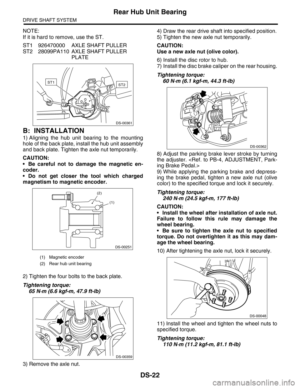
If it is hard to remove, use the ST.
ST1 926470000 AXLE SHAFT PULLER
ST2 28099PA110 AXLE SHAFT PULLER
PLATE
B: INSTALLATION
1) Aligning the hub unit bearing to the mounting
hole of the back plate, install the hub unit assembly
and back plate. Tighten the axle nut temporarily.
CAUTION:
•Be careful not to damage the magnetic en-
coder.
•Do not get closer the tool which charged
magnetism to magnetic encoder.
2) Tighten the four bolts to the back plate.
Tightening torque:
65 N·m (6.6 kgf-m, 47.9 ft-lb)
3) Remove the axle nut.
4) Draw the rear drive shaft into specified position.
5) Tighten the new axle nut temporarily.
CAUTION:
Use a new axle nut (olive color).
6) Install the disc rotor to hub.
7) Install the disc brake caliper on the rear housing.
Tightening torque:
60 N·m (6.1 kgf-m, 44.3 ft-lb)
8) Adjust the parking brake lever stroke by turning
the adjuster.
9) While applying the parking brake and depress-
ing the brake pedal, tighten a new axle nut (olive
color) to the specified torque and lock it securely.
Tightening torque:
240 N·m (24.5 kgf-m, 177 ft-lb)
CAUTION:
•Install the wheel after installation of axle nut.
Failure to follow this rule may damage the
wheel bearing.
•Be sure to tighten the axle nut to specified
torque. Do not overtighten it as this may dam-
age the wheel bearing.
10) After tightening the axle nut, lock it securely.
11) Install the wheel and tighten the wheel nuts to
specified torque.
Tightening torque:
110 N·m (11.2 kgf-m, 81.1 ft-lb)
(1) Magnetic encoder
(2) Rear hub unit bearing
ST2ST1
DS-00361
DS-00251
(2)
(1)
DS-00359
DS-00362
DS-00048
Page 841 of 2453

DS-24
Front Drive Shaft
DRIVE SHAFT SYSTEM
7. Front Drive Shaft
A: REMOVAL
1) Disconnect the ground cable from the battery.
2) Lift-up the vehicle, and remove the front wheels.
3) Lift the crimped section of axle nut.
4) Remove the axle nut using a socket wrench
while depressing the brake pedal.
CAUTION:
Remove the wheel before loosening the axle
nut. Failure to follow this rule may damage the
wheel bearings.
5) Remove the stabilizer link from front arm.
6) Disconnect the front arm ball joint from the front
housing.
7) Remove the front drive shaft assembly. If it is
hard to remove, use ST1 and ST2.
ST1 926470000 AXLE SHAFT PULLER
ST2 28099PA110 AXLE SHAFT PULLER
PLATE
8) Using a bar, remove the front drive shaft from
transmission.
CAUTION:
Be careful not to allow the bar to damage holder
area.
B: INSTALLATION
1) Using the ST, replace the differential side retain-
er oil seal with a new seal.
ST 18675AA000 DIFFERENTIAL SIDE OIL
SEAL INSTALLER
NOTE:
After pulling out the drive shaft, be sure to replace
with a new oil seal.
2) Insert the EBJ into hub splines.
3) Draw the drive shaft into specified position.
CAUTION:
Do not hammer drive shaft when installing it.
4) Tighten the axle nut temporarily.
5) Using the ST, install the front drive shaft to trans-
mission.
ST 28399SA010 OIL SEAL PROTECTOR
6) Connect the front arm ball joint to the front hous-
ing.
Tightening torque:
50 N·m (5.1 kgf-m, 36.9 ft-lb)
7) Install the stabilizer link.
Tightening torque:
60 N·m (6.1 kgf-m, 44.3 ft-lb)
CAUTION:
Be sure to use a new self-locking nut.
DS-00038
FS-00106
DS-00145
ST2
ST1
MT-00103
ST
AT-00110ST