2007 TOYOTA SIENNA length
[x] Cancel search: lengthPage 1642 of 3000
AX–198U151E AUTOMATIC TRANSAXLE – AUTOMATIC TRANSAXLE UNIT
AX
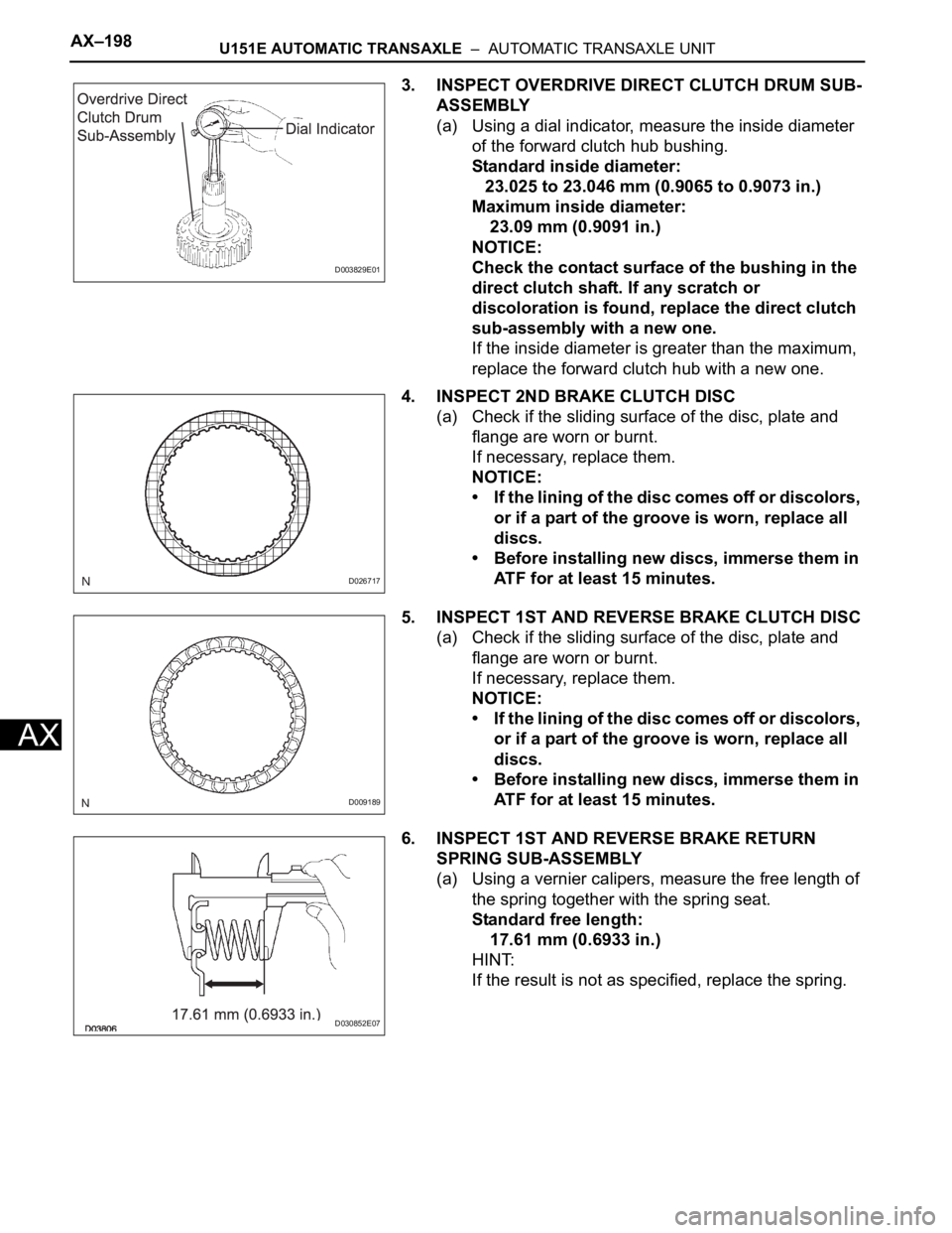
3. INSPECT OVERDRIVE DIRECT CLUTCH DRUM SUB-
ASSEMBLY
(a) Using a dial indicator, measure the inside diameter
of the forward clutch hub bushing.
Standard inside diameter:
23.025 to 23.046 mm (0.9065 to 0.9073 in.)
Maximum inside diameter:
23.09 mm (0.9091 in.)
NOTICE:
Check the contact surface of the bushing in the
direct clutch shaft. If any scratch or
discoloration is found, replace the direct clutch
sub-assembly with a new one.
If the inside diameter is greater than the maximum,
replace the forward clutch hub with a new one.
4. INSPECT 2ND BRAKE CLUTCH DISC
(a) Check if the sliding surface of the disc, plate and
flange are worn or burnt.
If necessary, replace them.
NOTICE:
• If the lining of the disc comes off or discolors,
or if a part of the groove is worn, replace all
discs.
• Before installing new discs, immerse them in
ATF for at least 15 minutes.
5. INSPECT 1ST AND REVERSE BRAKE CLUTCH DISC
(a) Check if the sliding surface of the disc, plate and
flange are worn or burnt.
If necessary, replace them.
NOTICE:
• If the lining of the disc comes off or discolors,
or if a part of the groove is worn, replace all
discs.
• Before installing new discs, immerse them in
ATF for at least 15 minutes.
6. INSPECT 1ST AND REVERSE BRAKE RETURN
SPRING SUB-ASSEMBLY
(a) Using a vernier calipers, measure the free length of
the spring together with the spring seat.
Standard free length:
17.61 mm (0.6933 in.)
HINT:
If the result is not as specified, replace the spring.
D003829E01
D026717
D009189
D030852E07
Page 1643 of 3000
U151E AUTOMATIC TRANSAXLE – AUTOMATIC TRANSAXLE UNITAX–199
AX
7. INSPECT UNDERDRIVE BRAKE RETURN SPRING
SUB-ASSEMBLY
(a) Using a vernier calipers, measure the free length of
the spring together with the spring seat.
Standard free length:
13.24 mm (0.5213 in.)
HINT:
If the result is not as specified, replace the spring.
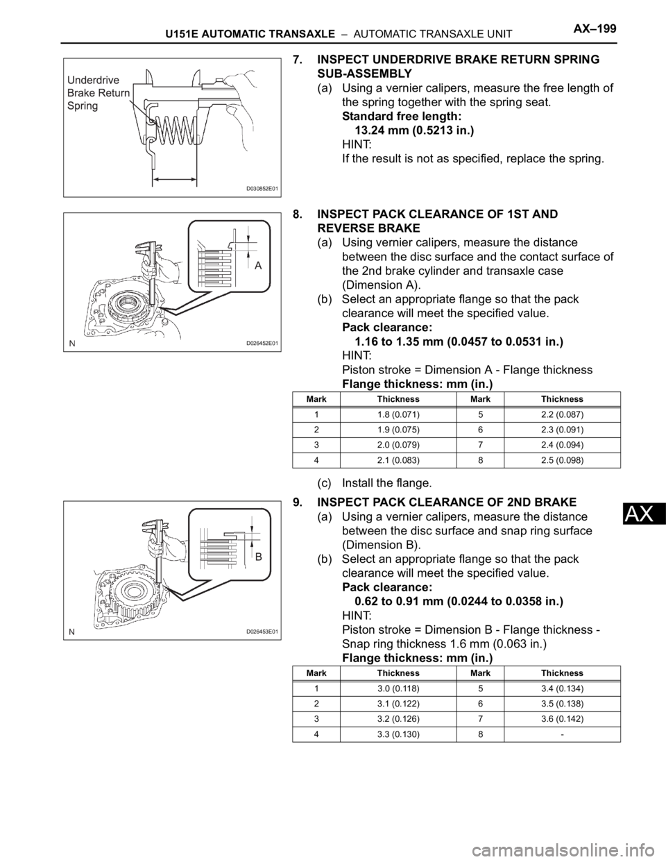
8. INSPECT PACK CLEARANCE OF 1ST AND
REVERSE BRAKE
(a) Using vernier calipers, measure the distance
between the disc surface and the contact surface of
the 2nd brake cylinder and transaxle case
(Dimension A).
(b) Select an appropriate flange so that the pack
clearance will meet the specified value.
Pack clearance:
1.16 to 1.35 mm (0.0457 to 0.0531 in.)
HINT:
Piston stroke = Dimension A - Flange thickness
Flange thickness: mm (in.)
(c) Install the flange.
9. INSPECT PACK CLEARANCE OF 2ND BRAKE
(a) Using a vernier calipers, measure the distance
between the disc surface and snap ring surface
(Dimension B).
(b) Select an appropriate flange so that the pack
clearance will meet the specified value.
Pack clearance:
0.62 to 0.91 mm (0.0244 to 0.0358 in.)
HINT:
Piston stroke = Dimension B - Flange thickness -
Snap ring thickness 1.6 mm (0.063 in.)
Flange thickness: mm (in.)
D030852E01
D026452E01
Mark Thickness Mark Thickness
1 1.8 (0.071) 5 2.2 (0.087)
2 1.9 (0.075) 6 2.3 (0.091)
3 2.0 (0.079) 7 2.4 (0.094)
4 2.1 (0.083) 8 2.5 (0.098)
D026453E01
Mark Thickness Mark Thickness
1 3.0 (0.118) 5 3.4 (0.134)
2 3.1 (0.122) 6 3.5 (0.138)
3 3.2 (0.126) 7 3.6 (0.142)
4 3.3 (0.130) 8 -
Page 1646 of 3000
U151E AUTOMATIC TRANSAXLE – FORWARD CLUTCHAX–243
AX
2. INSPECT FORWARD MULTIPLE DISC CLUTCH DISC
(a) Check if the sliding surface of the disc, plate and
flange are worn or burnt.
If necessary, replace them.
HINT:
• If the lining of the disc comes off or discolors, or if
a part of the groove is worn, replace all discs.
• Before installing new discs, immerse them in ATF
for at least 15 minutes.
3. INSPECT FORWARD CLUTCH RETURN SPRING
SUB-ASSEMBLY
(a) Using vernier calipers, measure the free length of
the spring together with the spring seat.
Standard free length:
26.74 mm (1.0528 in.)
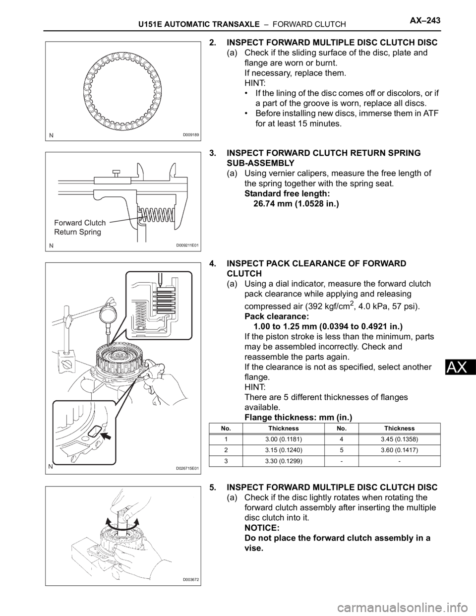
4. INSPECT PACK CLEARANCE OF FORWARD
CLUTCH
(a) Using a dial indicator, measure the forward clutch
pack clearance while applying and releasing
compressed air (392 kgf/cm
2, 4.0 kPa, 57 psi).
Pack clearance:
1.00 to 1.25 mm (0.0394 to 0.4921 in.)
If the piston stroke is less than the minimum, parts
may be assembled incorrectly. Check and
reassemble the parts again.
If the clearance is not as specified, select another
flange.
HINT:
There are 5 different thicknesses of flanges
available.
Flange thickness: mm (in.)
5. INSPECT FORWARD MULTIPLE DISC CLUTCH DISC
(a) Check if the disc lightly rotates when rotating the
forward clutch assembly after inserting the multiple
disc clutch into it.
NOTICE:
Do not place the forward clutch assembly in a
vise.
D009189
D009211E01
D026715E01
No. Thickness No. Thickness
1 3.00 (0.1181) 4 3.45 (0.1358)
2 3.15 (0.1240) 5 3.60 (0.1417)
3 3.30 (0.1299) - -
D003672
Page 1655 of 3000
U151E AUTOMATIC TRANSAXLE – FORWARD CLUTCHAX–243
AX
2. INSPECT FORWARD MULTIPLE DISC CLUTCH DISC
(a) Check if the sliding surface of the disc, plate and
flange are worn or burnt.
If necessary, replace them.
HINT:
• If the lining of the disc comes off or discolors, or if
a part of the groove is worn, replace all discs.
• Before installing new discs, immerse them in ATF
for at least 15 minutes.
3. INSPECT FORWARD CLUTCH RETURN SPRING
SUB-ASSEMBLY
(a) Using vernier calipers, measure the free length of
the spring together with the spring seat.
Standard free length:
26.74 mm (1.0528 in.)
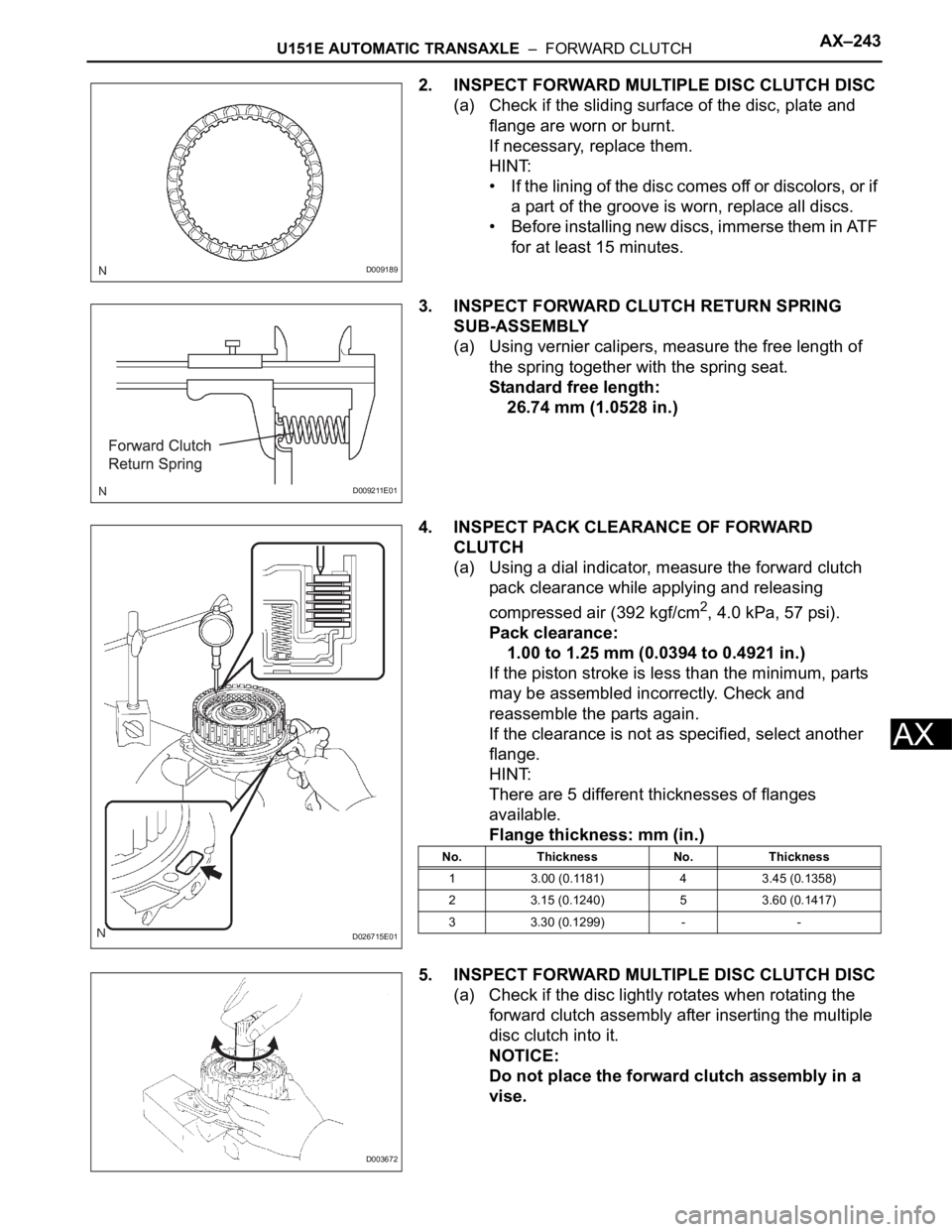
4. INSPECT PACK CLEARANCE OF FORWARD
CLUTCH
(a) Using a dial indicator, measure the forward clutch
pack clearance while applying and releasing
compressed air (392 kgf/cm
2, 4.0 kPa, 57 psi).
Pack clearance:
1.00 to 1.25 mm (0.0394 to 0.4921 in.)
If the piston stroke is less than the minimum, parts
may be assembled incorrectly. Check and
reassemble the parts again.
If the clearance is not as specified, select another
flange.
HINT:
There are 5 different thicknesses of flanges
available.
Flange thickness: mm (in.)
5. INSPECT FORWARD MULTIPLE DISC CLUTCH DISC
(a) Check if the disc lightly rotates when rotating the
forward clutch assembly after inserting the multiple
disc clutch into it.
NOTICE:
Do not place the forward clutch assembly in a
vise.
D009189
D009211E01
D026715E01
No. Thickness No. Thickness
1 3.00 (0.1181) 4 3.45 (0.1358)
2 3.15 (0.1240) 5 3.60 (0.1417)
3 3.30 (0.1299) - -
D003672
Page 1660 of 3000
AX–250U151E AUTOMATIC TRANSAXLE – DIRECT CLUTCH
AX
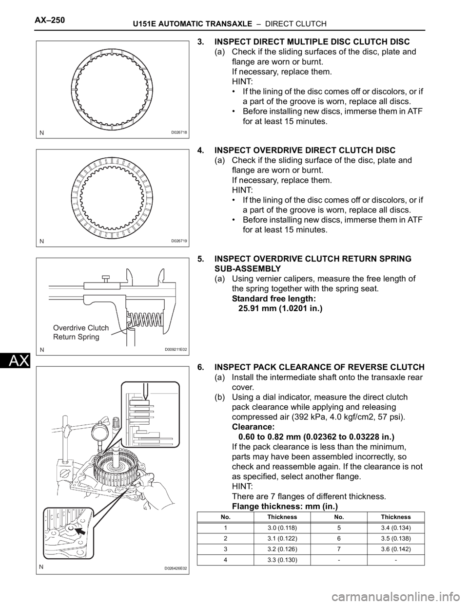
3. INSPECT DIRECT MULTIPLE DISC CLUTCH DISC
(a) Check if the sliding surfaces of the disc, plate and
flange are worn or burnt.
If necessary, replace them.
HINT:
• If the lining of the disc comes off or discolors, or if
a part of the groove is worn, replace all discs.
• Before installing new discs, immerse them in ATF
for at least 15 minutes.
4. INSPECT OVERDRIVE DIRECT CLUTCH DISC
(a) Check if the sliding surface of the disc, plate and
flange are worn or burnt.
If necessary, replace them.
HINT:
• If the lining of the disc comes off or discolors, or if
a part of the groove is worn, replace all discs.
• Before installing new discs, immerse them in ATF
for at least 15 minutes.
5. INSPECT OVERDRIVE CLUTCH RETURN SPRING
SUB-ASSEMBLY
(a) Using vernier calipers, measure the free length of
the spring together with the spring seat.
Standard free length:
25.91 mm (1.0201 in.)
6. INSPECT PACK CLEARANCE OF REVERSE CLUTCH
(a) Install the intermediate shaft onto the transaxle rear
cover.
(b) Using a dial indicator, measure the direct clutch
pack clearance while applying and releasing
compressed air (392 kPa, 4.0 kgf/cm2, 57 psi).
Clearance:
0.60 to 0.82 mm (0.02362 to 0.03228 in.)
If the pack clearance is less than the minimum,
parts may have been assembled incorrectly, so
check and reassemble again. If the clearance is not
as specified, select another flange.
HINT:
There are 7 flanges of different thickness.
Flange thickness: mm (in.)
D026718
D026719
D009211E02
D026426E02
No. Thickness No. Thickness
1 3.0 (0.118) 5 3.4 (0.134)
2 3.1 (0.122) 6 3.5 (0.138)
3 3.2 (0.126) 7 3.6 (0.142)
4 3.3 (0.130) - -
Page 1667 of 3000
U151E AUTOMATIC TRANSAXLE – UNDERDRIVE PLANETARY GEARAX–257
AX
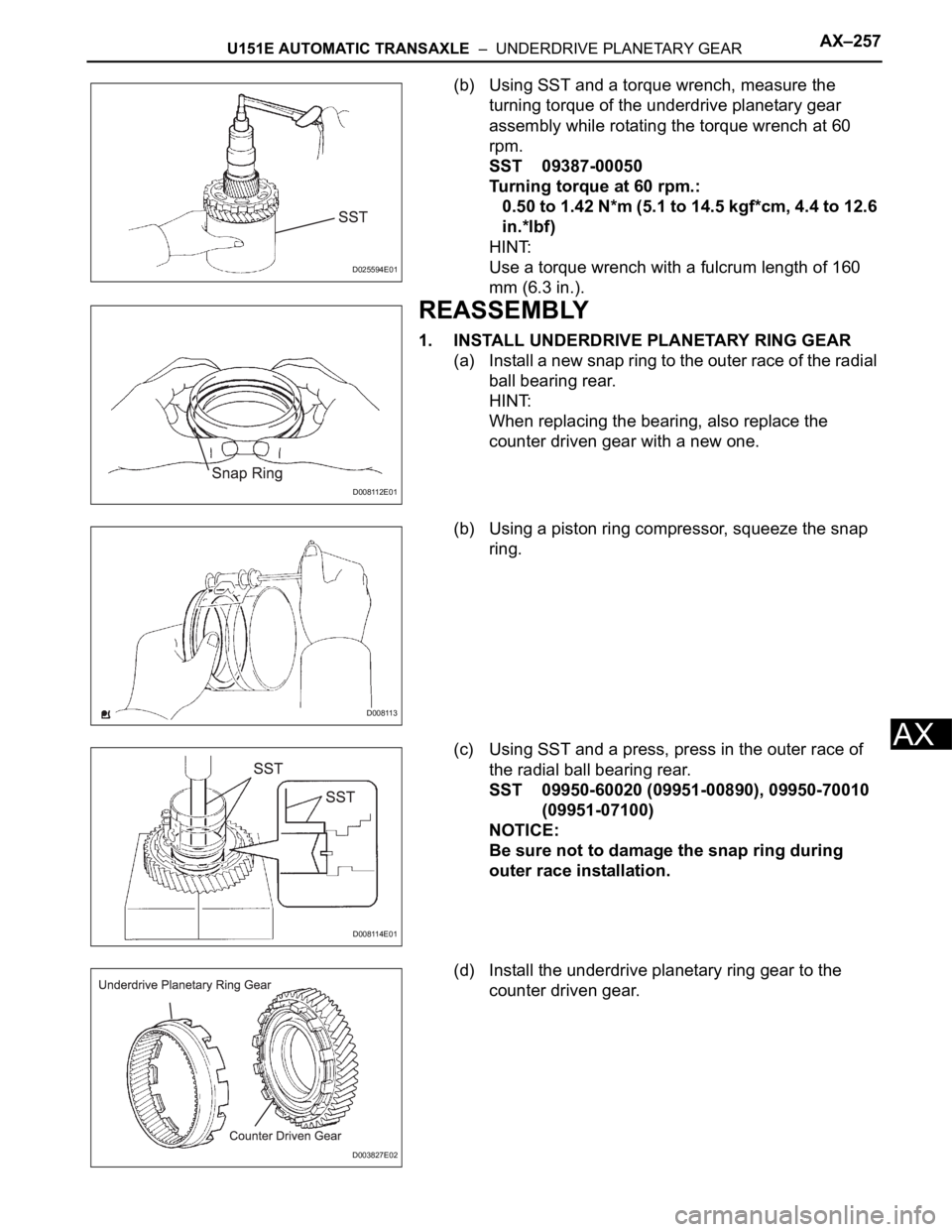
(b) Using SST and a torque wrench, measure the
turning torque of the underdrive planetary gear
assembly while rotating the torque wrench at 60
rpm.
SST 09387-00050
Turning torque at 60 rpm.:
0.50 to 1.42 N*m (5.1 to 14.5 kgf*cm, 4.4 to 12.6
in.*lbf)
HINT:
Use a torque wrench with a fulcrum length of 160
mm (6.3 in.).
REASSEMBLY
1. INSTALL UNDERDRIVE PLANETARY RING GEAR
(a) Install a new snap ring to the outer race of the radial
ball bearing rear.
HINT:
When replacing the bearing, also replace the
counter driven gear with a new one.
(b) Using a piston ring compressor, squeeze the snap
ring.
(c) Using SST and a press, press in the outer race of
the radial ball bearing rear.
SST 09950-60020 (09951-00890), 09950-70010
(09951-07100)
NOTICE:
Be sure not to damage the snap ring during
outer race installation.
(d) Install the underdrive planetary ring gear to the
counter driven gear.
D025594E01
D008112E01
D008113
D008114E01
D003827E02
Page 1669 of 3000
U151E AUTOMATIC TRANSAXLE – UNDERDRIVE PLANETARY GEARAX–259
AX
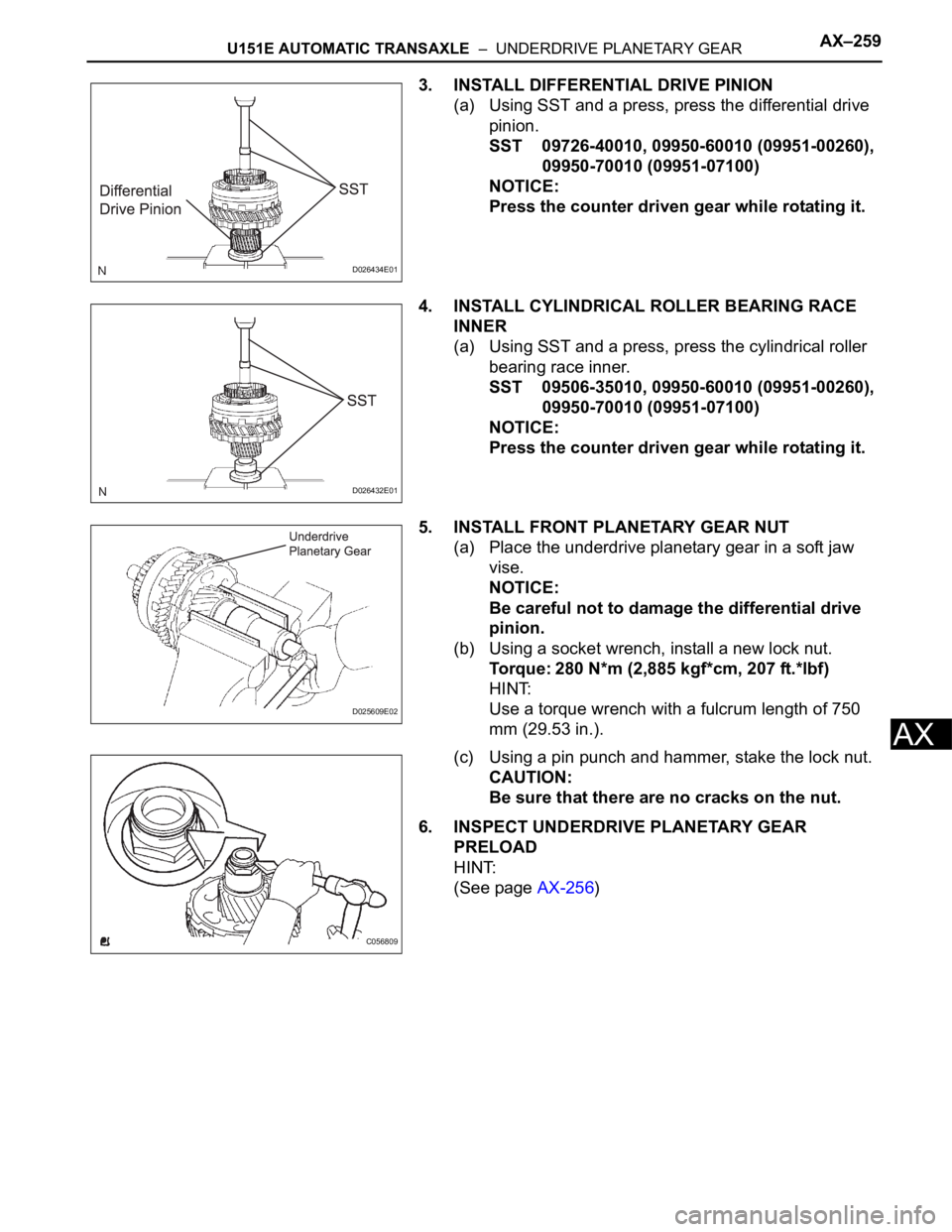
3. INSTALL DIFFERENTIAL DRIVE PINION
(a) Using SST and a press, press the differential drive
pinion.
SST 09726-40010, 09950-60010 (09951-00260),
09950-70010 (09951-07100)
NOTICE:
Press the counter driven gear while rotating it.
4. INSTALL CYLINDRICAL ROLLER BEARING RACE
INNER
(a) Using SST and a press, press the cylindrical roller
bearing race inner.
SST 09506-35010, 09950-60010 (09951-00260),
09950-70010 (09951-07100)
NOTICE:
Press the counter driven gear while rotating it.
5. INSTALL FRONT PLANETARY GEAR NUT
(a) Place the underdrive planetary gear in a soft jaw
vise.
NOTICE:
Be careful not to damage the differential drive
pinion.
(b) Using a socket wrench, install a new lock nut.
Torque: 280 N*m (2,885 kgf*cm, 207 ft.*lbf)
HINT:
Use a torque wrench with a fulcrum length of 750
mm (29.53 in.).
(c) Using a pin punch and hammer, stake the lock nut.
CAUTION:
Be sure that there are no cracks on the nut.
6. INSPECT UNDERDRIVE PLANETARY GEAR
PRELOAD
HINT:
(See page AX-256)
D026434E01
D026432E01
D025609E02
C056809
Page 1673 of 3000
U151E AUTOMATIC TRANSAXLE – UNDERDRIVE CLUTCHAX–263
AX
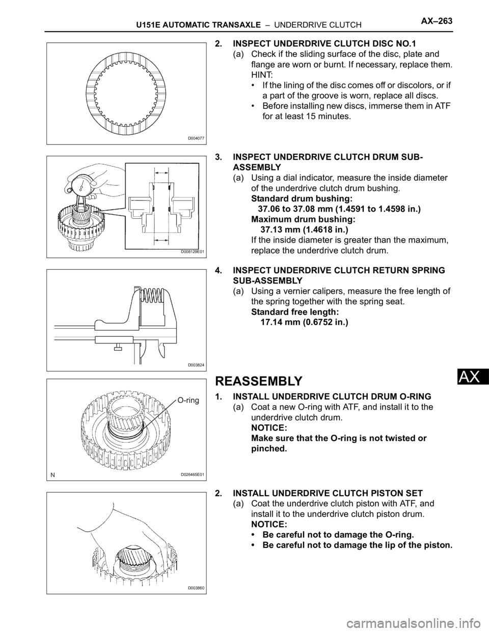
2. INSPECT UNDERDRIVE CLUTCH DISC NO.1
(a) Check if the sliding surface of the disc, plate and
flange are worn or burnt. If necessary, replace them.
HINT:
• If the lining of the disc comes off or discolors, or if
a part of the groove is worn, replace all discs.
• Before installing new discs, immerse them in ATF
for at least 15 minutes.
3. INSPECT UNDERDRIVE CLUTCH DRUM SUB-
ASSEMBLY
(a) Using a dial indicator, measure the inside diameter
of the underdrive clutch drum bushing.
Standard drum bushing:
37.06 to 37.08 mm (1.4591 to 1.4598 in.)
Maximum drum bushing:
37.13 mm (1.4618 in.)
If the inside diameter is greater than the maximum,
replace the underdrive clutch drum.
4. INSPECT UNDERDRIVE CLUTCH RETURN SPRING
SUB-ASSEMBLY
(a) Using a vernier calipers, measure the free length of
the spring together with the spring seat.
Standard free length:
17.14 mm (0.6752 in.)
REASSEMBLY
1. INSTALL UNDERDRIVE CLUTCH DRUM O-RING
(a) Coat a new O-ring with ATF, and install it to the
underdrive clutch drum.
NOTICE:
Make sure that the O-ring is not twisted or
pinched.
2. INSTALL UNDERDRIVE CLUTCH PISTON SET
(a) Coat the underdrive clutch piston with ATF, and
install it to the underdrive clutch piston drum.
NOTICE:
• Be careful not to damage the O-ring.
• Be careful not to damage the lip of the piston.
D004077
D008129E01
D003824
D026465E01
D003860