Page 1209 of 3000
2GR-FE EMISSION CONTROL – HEATED OXYGEN SENSOR (for 4WD)EC–41
EC
3. INSTALL HEATED OXYGEN SENSOR (for Bank 1
Sensor 2)
(a) Using SST, install the heated oxygen sensor.
SST 09224-00010
Torque: 40 N*m (408 kgf*cm, 30 ft.*lbf) for use
with SST
44 N*m (449 kgf*cm, 32 ft.*lbf) for use
without SST
(b) Connect the heated oxygen sensor (for Bank 1
Sensor 2) connector.
HINT:
• Use a torque wrench with a fulcrum length of 30
cm (11.81 in.).
• Make sure that SST and a wrench are connected
in a straight line.
4. CONNECT CABLE TO NEGATIVE BATTERY
TERMINAL
5. INSPECT FOR EXHAUST GAS LEAK
A163385E01
Page 1224 of 3000
2GR-FE EXHAUST – EXHAUST PIPE (for 2WD)EX–5
EX
INSTALLATION
1. INSTALL HEATED OXYGEN SENSOR (for Bank 2
Sensor 2) (See page EC-34)
2. INSTALL FRONT EXHAUST PIPE ASSEMBLY
(a) Install 2 new gaskets to the front exhaust pipe
assembly.
(b) Install the front exhaust pipe assembly with the 4
nuts.
Torque: 62 N*m (632 kgf*cm, 46 ft.*lbf)
3. INSTALL CENTER EXHAUST PIPE ASSEMBLY
(a) Using a vernier caliper, measure the free length of
the compression spring.
Minimum length:
38.86 mm (1.5299 in.)
If the length is less than the minimum, replace the
compression spring.
(b) Install a new gasket by hand so that its surface is
flush with the front exhaust pipe assembly.
NOTICE:
• Make sure the gasket is facing the correct
direction.
• Do not reuse the old gasket.
• Do not push in the gasket while installing the
center exhaust pipe assembly.
(c) Connect the 2 exhaust pipe supports, and install the
center exhaust pipe assembly.
A162908
A160224
A133205E01
Page 1293 of 3000
LU–142GR-FE LUBRICATION – OIL PUMP
LU
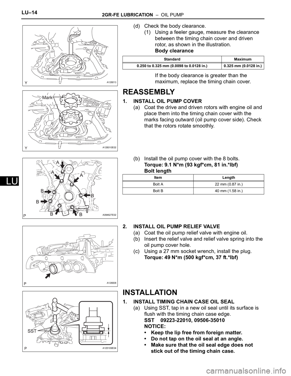
(d) Check the body clearance.
(1) Using a feeler gauge, measure the clearance
between the timing chain cover and driven
rotor, as shown in the illustration.
Body clearance
If the body clearance is greater than the
maximum, replace the timing chain cover.
REASSEMBLY
1. INSTALL OIL PUMP COVER
(a) Coat the drive and driven rotors with engine oil and
place them into the timing chain cover with the
marks facing outward (oil pump cover side). Check
that the rotors rotate smoothly.
(b) Install the oil pump cover with the 8 bolts.
Torque: 9.1 N*m (93 kgf*cm, 81 in.*lbf)
Bolt length
2. INSTALL OIL PUMP RELIEF VALVE
(a) Coat the oil pump relief valve with engine oil.
(b) Insert the relief valve and relief valve spring into the
oil pump cover hole.
(c) Using a 27 mm socket wrench, install the plug.
Torque: 49 N*m (500 kgf*cm, 37 ft.*lbf)
INSTALLATION
1. INSTALL TIMING CHAIN CASE OIL SEAL
(a) Using SST, tap in a new oil seal until its surface is
flush with the timing chain case edge.
SST 09223-22010, 09506-35010
NOTICE:
• Keep the lip free from foreign matter.
• Do not tap on the oil seal at an angle.
• Make sure that the oil seal edge does not
stick out of the timing chain case.
A128013
Standard Maximum
0.250 to 0.325 mm (0.0098 to 0.0128 in.) 0.325 mm (0.0128 in.)
A128010E02
A094627E02
Item Length
Bolt A 22 mm (0.87 in.)
Bolt B 40 mm (1.58 in.)
A128008
A125109E04
Page 1297 of 3000
LU–182GR-FE LUBRICATION – OIL PUMP
LU
Bolt length
NOTICE:
Make sure that there is no oil on the bolt
threads.
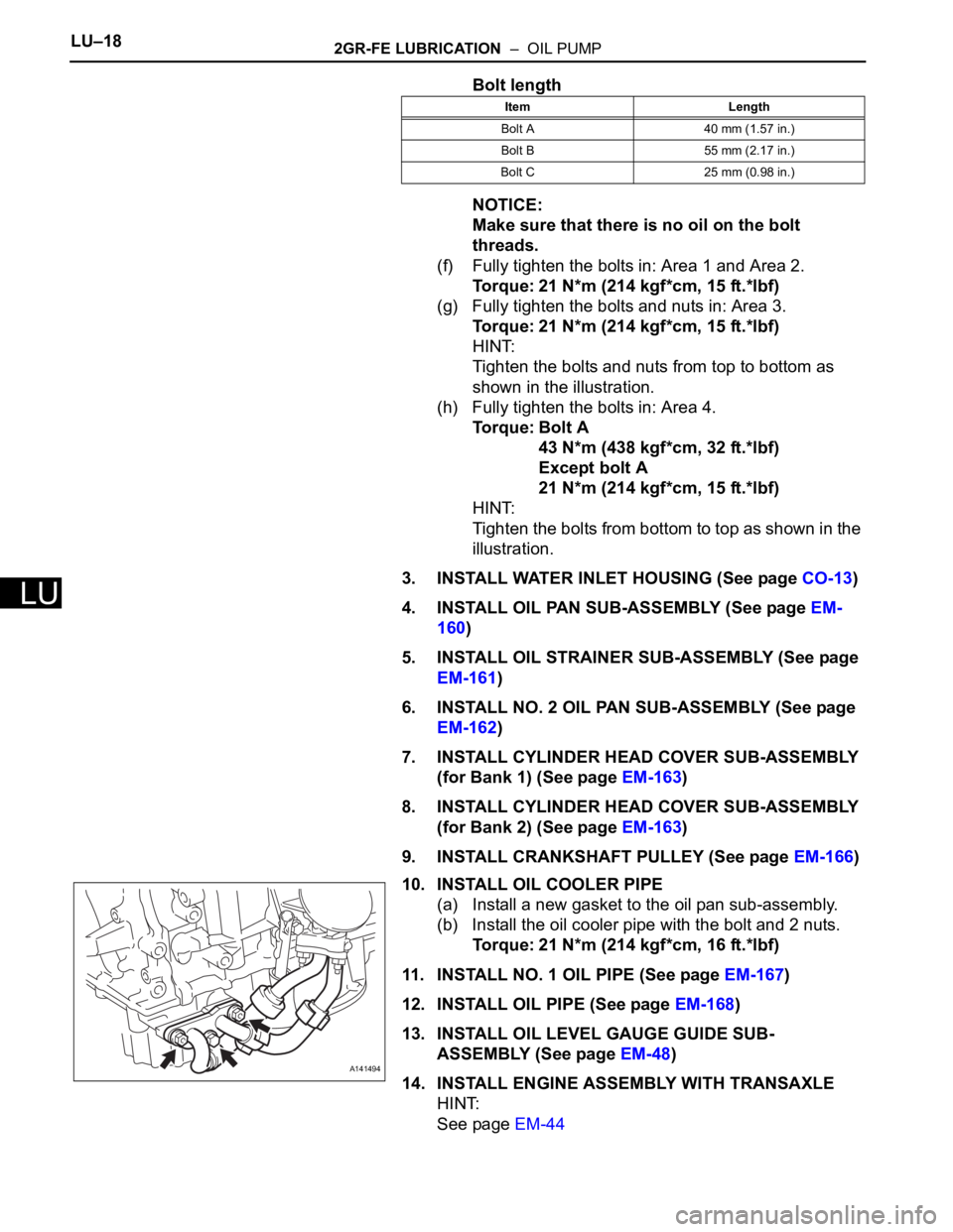
(f) Fully tighten the bolts in: Area 1 and Area 2.
Torque: 21 N*m (214 kgf*cm, 15 ft.*lbf)
(g) Fully tighten the bolts and nuts in: Area 3.
Torque: 21 N*m (214 kgf*cm, 15 ft.*lbf)
HINT:
Tighten the bolts and nuts from top to bottom as
shown in the illustration.
(h) Fully tighten the bolts in: Area 4.
Torque: Bolt A
43 N*m (438 kgf*cm, 32 ft.*lbf)
Except bolt A
21 N*m (214 kgf*cm, 15 ft.*lbf)
HINT:
Tighten the bolts from bottom to top as shown in the
illustration.
3. INSTALL WATER INLET HOUSING (See page CO-13)
4. INSTALL OIL PAN SUB-ASSEMBLY (See page EM-
160)
5. INSTALL OIL STRAINER SUB-ASSEMBLY (See page
EM-161)
6. INSTALL NO. 2 OIL PAN SUB-ASSEMBLY (See page
EM-162)
7. INSTALL CYLINDER HEAD COVER SUB-ASSEMBLY
(for Bank 1) (See page EM-163)
8. INSTALL CYLINDER HEAD COVER SUB-ASSEMBLY
(for Bank 2) (See page EM-163)
9. INSTALL CRANKSHAFT PULLEY (See page EM-166)
10. INSTALL OIL COOLER PIPE
(a) Install a new gasket to the oil pan sub-assembly.
(b) Install the oil cooler pipe with the bolt and 2 nuts.
Torque: 21 N*m (214 kgf*cm, 16 ft.*lbf)
11. INSTALL NO. 1 OIL PIPE (See page EM-167)
12. INSTALL OIL PIPE (See page EM-168)
13. INSTALL OIL LEVEL GAUGE GUIDE SUB-
ASSEMBLY (See page EM-48)
14. INSTALL ENGINE ASSEMBLY WITH TRANSAXLE
HINT:
See page EM-44
Item Length
Bolt A 40 mm (1.57 in.)
Bolt B 55 mm (2.17 in.)
Bolt C 25 mm (0.98 in.)
A141494
Page 1306 of 3000
LU–142GR-FE LUBRICATION – OIL PUMP
LU
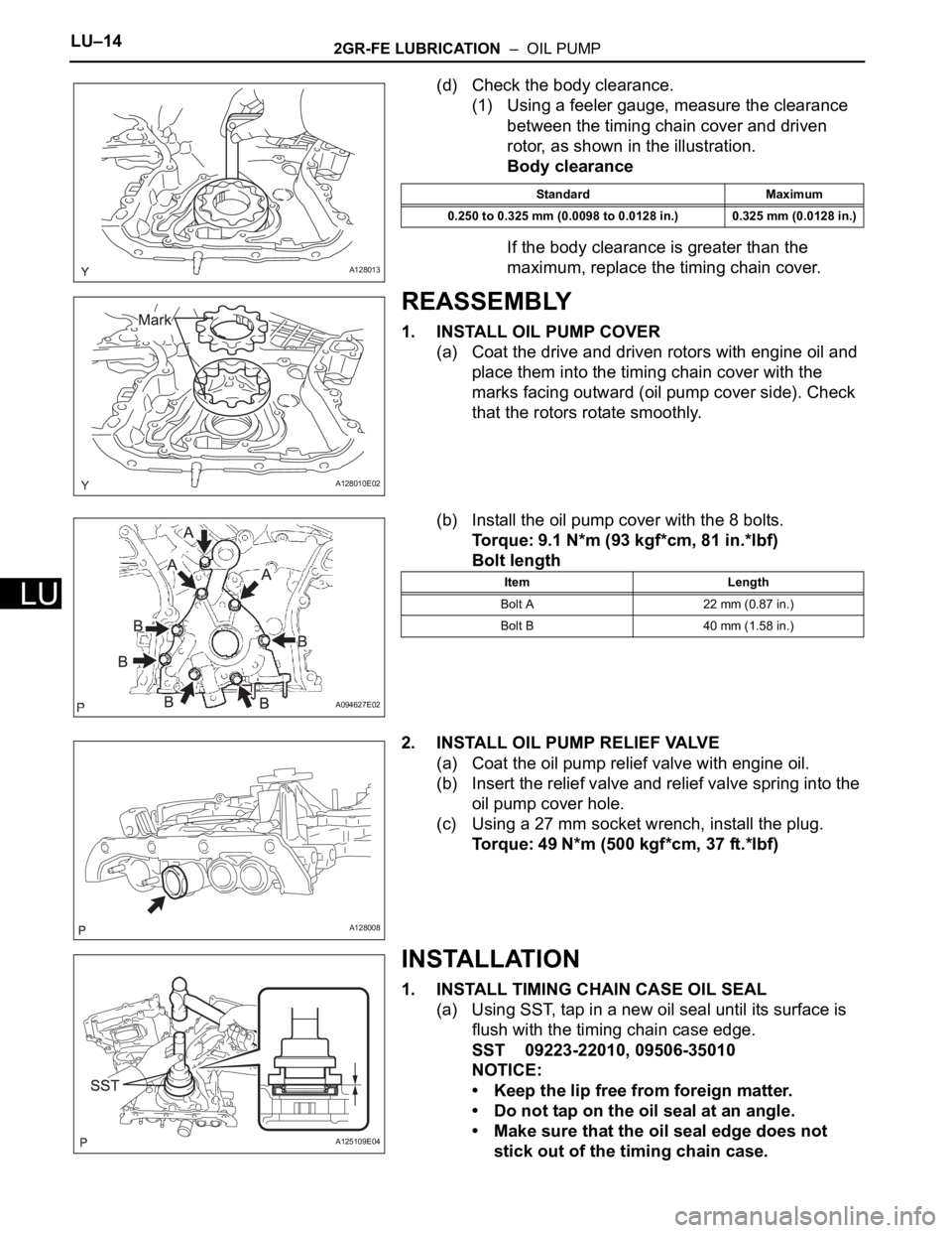
(d) Check the body clearance.
(1) Using a feeler gauge, measure the clearance
between the timing chain cover and driven
rotor, as shown in the illustration.
Body clearance
If the body clearance is greater than the
maximum, replace the timing chain cover.
REASSEMBLY
1. INSTALL OIL PUMP COVER
(a) Coat the drive and driven rotors with engine oil and
place them into the timing chain cover with the
marks facing outward (oil pump cover side). Check
that the rotors rotate smoothly.
(b) Install the oil pump cover with the 8 bolts.
Torque: 9.1 N*m (93 kgf*cm, 81 in.*lbf)
Bolt length
2. INSTALL OIL PUMP RELIEF VALVE
(a) Coat the oil pump relief valve with engine oil.
(b) Insert the relief valve and relief valve spring into the
oil pump cover hole.
(c) Using a 27 mm socket wrench, install the plug.
Torque: 49 N*m (500 kgf*cm, 37 ft.*lbf)
INSTALLATION
1. INSTALL TIMING CHAIN CASE OIL SEAL
(a) Using SST, tap in a new oil seal until its surface is
flush with the timing chain case edge.
SST 09223-22010, 09506-35010
NOTICE:
• Keep the lip free from foreign matter.
• Do not tap on the oil seal at an angle.
• Make sure that the oil seal edge does not
stick out of the timing chain case.
A128013
Standard Maximum
0.250 to 0.325 mm (0.0098 to 0.0128 in.) 0.325 mm (0.0128 in.)
A128010E02
A094627E02
Item Length
Bolt A 22 mm (0.87 in.)
Bolt B 40 mm (1.58 in.)
A128008
A125109E04
Page 1310 of 3000
LU–182GR-FE LUBRICATION – OIL PUMP
LU
Bolt length
NOTICE:
Make sure that there is no oil on the bolt
threads.
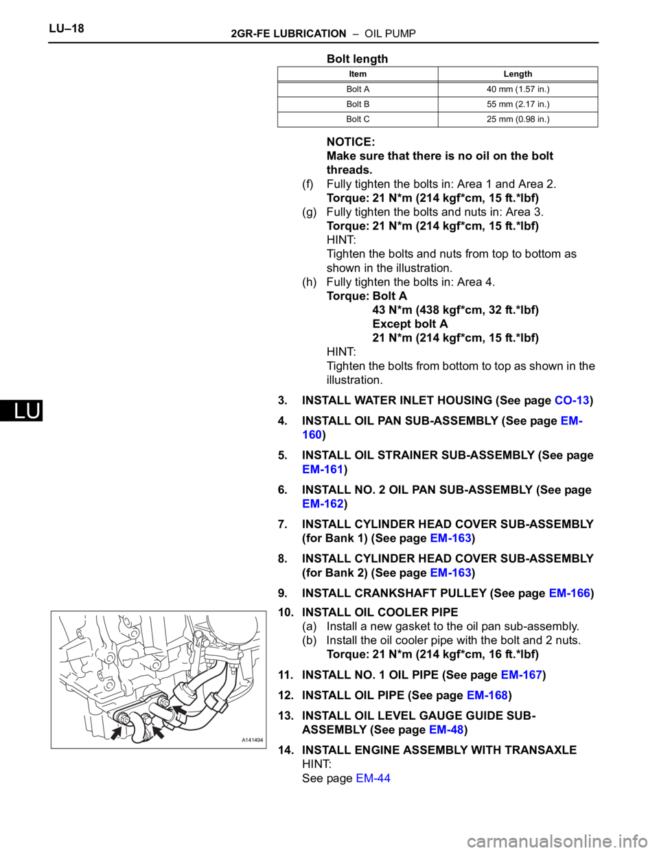
(f) Fully tighten the bolts in: Area 1 and Area 2.
Torque: 21 N*m (214 kgf*cm, 15 ft.*lbf)
(g) Fully tighten the bolts and nuts in: Area 3.
Torque: 21 N*m (214 kgf*cm, 15 ft.*lbf)
HINT:
Tighten the bolts and nuts from top to bottom as
shown in the illustration.
(h) Fully tighten the bolts in: Area 4.
Torque: Bolt A
43 N*m (438 kgf*cm, 32 ft.*lbf)
Except bolt A
21 N*m (214 kgf*cm, 15 ft.*lbf)
HINT:
Tighten the bolts from bottom to top as shown in the
illustration.
3. INSTALL WATER INLET HOUSING (See page CO-13)
4. INSTALL OIL PAN SUB-ASSEMBLY (See page EM-
160)
5. INSTALL OIL STRAINER SUB-ASSEMBLY (See page
EM-161)
6. INSTALL NO. 2 OIL PAN SUB-ASSEMBLY (See page
EM-162)
7. INSTALL CYLINDER HEAD COVER SUB-ASSEMBLY
(for Bank 1) (See page EM-163)
8. INSTALL CYLINDER HEAD COVER SUB-ASSEMBLY
(for Bank 2) (See page EM-163)
9. INSTALL CRANKSHAFT PULLEY (See page EM-166)
10. INSTALL OIL COOLER PIPE
(a) Install a new gasket to the oil pan sub-assembly.
(b) Install the oil cooler pipe with the bolt and 2 nuts.
Torque: 21 N*m (214 kgf*cm, 16 ft.*lbf)
11. INSTALL NO. 1 OIL PIPE (See page EM-167)
12. INSTALL OIL PIPE (See page EM-168)
13. INSTALL OIL LEVEL GAUGE GUIDE SUB-
ASSEMBLY (See page EM-48)
14. INSTALL ENGINE ASSEMBLY WITH TRANSAXLE
HINT:
See page EM-44
Item Length
Bolt A 40 mm (1.57 in.)
Bolt B 55 mm (2.17 in.)
Bolt C 25 mm (0.98 in.)
A141494
Page 1324 of 3000
ST–102GR-FE STARTING – STARTER
ST
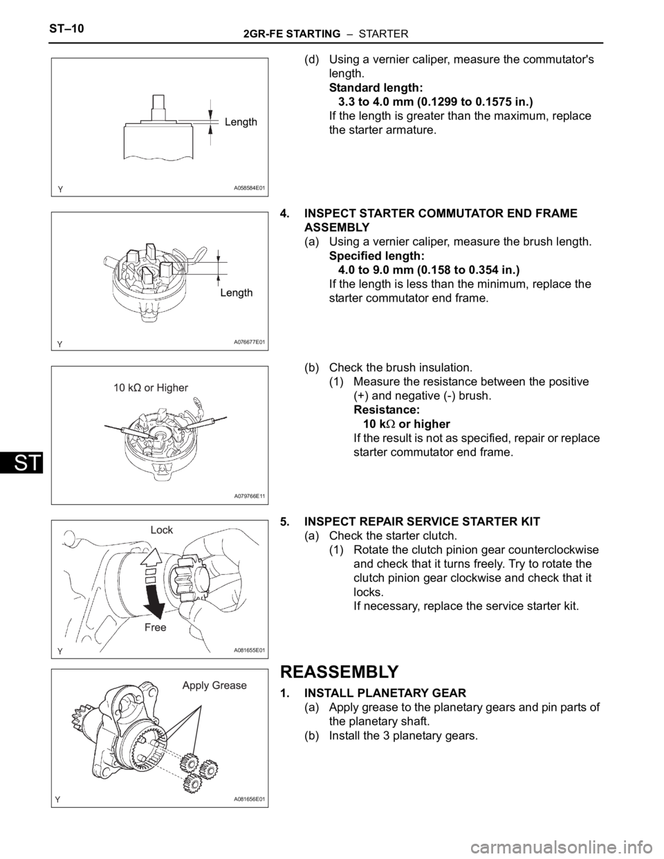
(d) Using a vernier caliper, measure the commutator's
length.
Standard length:
3.3 to 4.0 mm (0.1299 to 0.1575 in.)
If the length is greater than the maximum, replace
the starter armature.
4. INSPECT STARTER COMMUTATOR END FRAME
ASSEMBLY
(a) Using a vernier caliper, measure the brush length.
Specified length:
4.0 to 9.0 mm (0.158 to 0.354 in.)
If the length is less than the minimum, replace the
starter commutator end frame.
(b) Check the brush insulation.
(1) Measure the resistance between the positive
(+) and negative (-) brush.
Resistance:
10 k
or higher
If the result is not as specified, repair or replace
starter commutator end frame.
5. INSPECT REPAIR SERVICE STARTER KIT
(a) Check the starter clutch.
(1) Rotate the clutch pinion gear counterclockwise
and check that it turns freely. Try to rotate the
clutch pinion gear clockwise and check that it
locks.
If necessary, replace the service starter kit.
REASSEMBLY
1. INSTALL PLANETARY GEAR
(a) Apply grease to the planetary gears and pin parts of
the planetary shaft.
(b) Install the 3 planetary gears.
A058584E01
A076677E01
A079766E11
A081655E01
A081656E01
Page 1325 of 3000
2GR-FE STARTING – STARTERST–11
ST
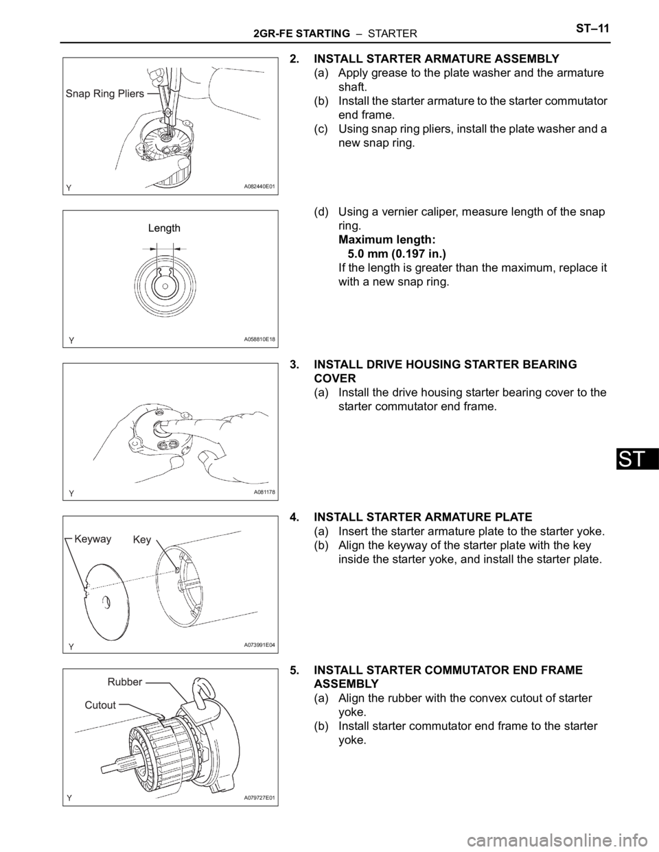
2. INSTALL STARTER ARMATURE ASSEMBLY
(a) Apply grease to the plate washer and the armature
shaft.
(b) Install the starter armature to the starter commutator
end frame.
(c) Using snap ring pliers, install the plate washer and a
new snap ring.
(d) Using a vernier caliper, measure length of the snap
ring.
Maximum length:
5.0 mm (0.197 in.)
If the length is greater than the maximum, replace it
with a new snap ring.
3. INSTALL DRIVE HOUSING STARTER BEARING
COVER
(a) Install the drive housing starter bearing cover to the
starter commutator end frame.
4. INSTALL STARTER ARMATURE PLATE
(a) Insert the starter armature plate to the starter yoke.
(b) Align the keyway of the starter plate with the key
inside the starter yoke, and install the starter plate.
5. INSTALL STARTER COMMUTATOR END FRAME
ASSEMBLY
(a) Align the rubber with the convex cutout of starter
yoke.
(b) Install starter commutator end frame to the starter
yoke.
A082440E01
A058810E18
A081178
A073991E04
A079727E01