Page 2707 of 3000

POWER STEERING – RACK AND PINION POWER STEERING GEARPS–39
PS
HINT:
Perform the same procedure on the other side.
17. INSTALL STEERING RACK BOOT CLIP
(a) Using pliers, install the 2 rack boot clips.
18. INSTALL TIE ROD ASSEMBLY LH
(a) Screw the lock nut and tie rod assembly onto the
rack end sub-assembly until the matchmarks are
aligned.
HINT:
After adjusting toe-in, torque the lock nut.
19. INSTALL TIE ROD ASSEMBLY RH
HINT:
Perform the same procedure on the other side.
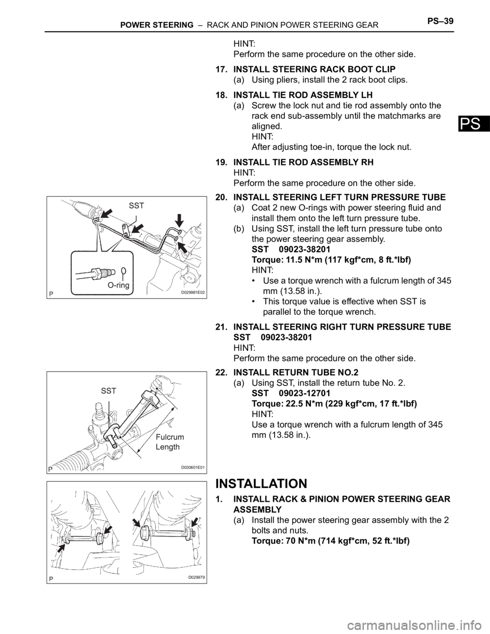
20. INSTALL STEERING LEFT TURN PRESSURE TUBE
(a) Coat 2 new O-rings with power steering fluid and
install them onto the left turn pressure tube.
(b) Using SST, install the left turn pressure tube onto
the power steering gear assembly.
SST 09023-38201
Torque: 11.5 N*m (117 kgf*cm, 8 ft.*lbf)
HINT:
• Use a torque wrench with a fulcrum length of 345
mm (13.58 in.).
• This torque value is effective when SST is
parallel to the torque wrench.
21. INSTALL STEERING RIGHT TURN PRESSURE TUBE
SST 09023-38201
HINT:
Perform the same procedure on the other side.
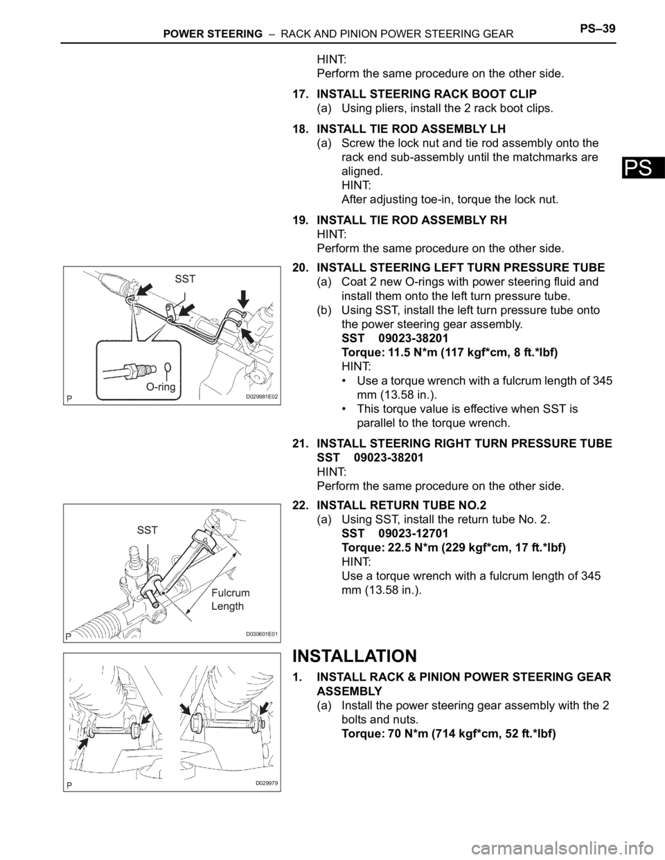
22. INSTALL RETURN TUBE NO.2
(a) Using SST, install the return tube No. 2.
SST 09023-12701
Torque: 22.5 N*m (229 kgf*cm, 17 ft.*lbf)
HINT:
Use a torque wrench with a fulcrum length of 345
mm (13.58 in.).
INSTALLATION
1. INSTALL RACK & PINION POWER STEERING GEAR
ASSEMBLY
(a) Install the power steering gear assembly with the 2
bolts and nuts.
Torque: 70 N*m (714 kgf*cm, 52 ft.*lbf)
D029981E02
D030601E01
D029979
Page 2708 of 3000
PS–40POWER STEERING – RACK AND PINION POWER STEERING GEAR
PS
2. CONNECT PRESSURE FEED TUBE ASSEMBLY
(a) Connect the pressure feed tube assembly to the
power steering gear assembly.
(b) Install the clip.
(c) Using SST, connect the return tube assembly to the
power steering gear assembly.
SST 09023-12701
Torque: 22.5 N*m (229 kgf*cm, 17 ft.*lbf)
HINT:
• Use a torque wrench with a fulcrum length of 300
mm (11.81 in.).
• This torque value is effective when SST is
parallel to the torque wrench.
(d) Install the tube clamp with the bolt.
Torque: 9.8 N*m (100 kgf*cm, 87 in.*lbf)
(e) Install the tube clamp with the nut.
Torque: 9.8 N*m (100 kgf*cm, 87 in.*lbf)
D029970
D029977E01
D029974
D029975
Page 2725 of 3000

PS–14POWER STEERING – VANE PUMP
PS
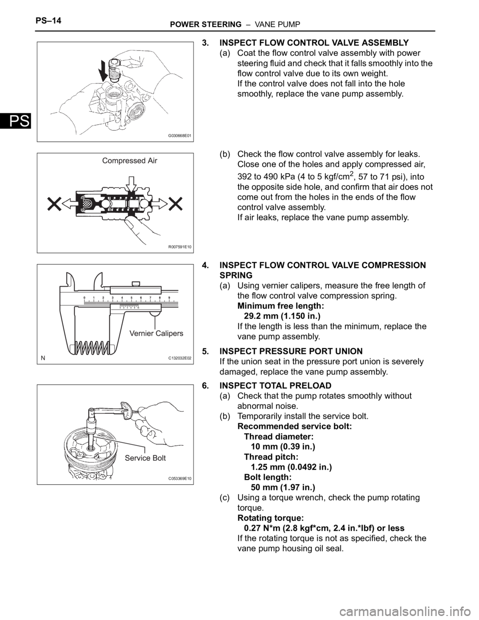
3. INSPECT FLOW CONTROL VALVE ASSEMBLY
(a) Coat the flow control valve assembly with power
steering fluid and check that it falls smoothly into the
flow control valve due to its own weight.
If the control valve does not fall into the hole
smoothly, replace the vane pump assembly.
(b) Check the flow control valve assembly for leaks.
Close one of the holes and apply compressed air,
392 to 490 kPa (4 to 5 kgf/cm
2, 57 to 71 psi), into
the opposite side hole, and confirm that air does not
come out from the holes in the ends of the flow
control valve assembly.
If air leaks, replace the vane pump assembly.
4. INSPECT FLOW CONTROL VALVE COMPRESSION
SPRING
(a) Using vernier calipers, measure the free length of
the flow control valve compression spring.
Minimum free length:
29.2 mm (1.150 in.)
If the length is less than the minimum, replace the
vane pump assembly.
5. INSPECT PRESSURE PORT UNION
If the union seat in the pressure port union is severely
damaged, replace the vane pump assembly.
6. INSPECT TOTAL PRELOAD
(a) Check that the pump rotates smoothly without
abnormal noise.
(b) Temporarily install the service bolt.
Recommended service bolt:
Thread diameter:
10 mm (0.39 in.)
Thread pitch:
1.25 mm (0.0492 in.)
Bolt length:
50 mm (1.97 in.)
(c) Using a torque wrench, check the pump rotating
torque.
Rotating torque:
0.27 N*m (2.8 kgf*cm, 2.4 in.*lbf) or less
If the rotating torque is not as specified, check the
vane pump housing oil seal.
G030668E01
R007591E10
C132032E02
C053369E10
Page 2730 of 3000
POWER STEERING – VANE PUMPPS–19
PS
INSTALLATION
1. INSTALL VANE PUMP ASSEMBLY
(a) Temporarily install the bolt to the vane pump
assembly.
(b) Install the vane pump assembly.
(c) Temporarily install the bolt (B).
(d) Using SST, tighten the 2 bolts.
SST 09249-63010
Torque: Without SST
43 N*m (439 kgf*cm, 32 ft.*lbf)
With SST
29 N*m (294 kgf*cm, 21 ft.*lbf)
NOTICE:
• Use a torque wrench with a fulcrum length of
300 mm (11.81 in.).
• This torque value is accurate when SST is
parallel to the torque wrench.
2. CONNECT POWER STEERING FLUID PRESSURE
SWITCH CONNECTOR
(a) Connect the connector to the power steering fluid
pressure switch.
3. CONNECT PRESSURE FEED TUBE ASSEMBLY
(a) Install a new gasket to the pressure feed tube
assembly.
C135238
C159000E01
C161547
Page 2748 of 3000
POWER STEERING – RACK AND PINION POWER STEERING GEARPS–37
PS
(i) Using SST, hold the rack guide spring cap and using
another SST, torque the rack guide spring cap nut.
SST 09616-00011, 09922-10010
Torque: 48 N*m (489 kgf*cm, 35 ft.*lbf)
NOTICE:
Use SST 09922-10010 in the direction shown in
the illustration.
HINT:
Use a torque wrench with a fulcrum length of 345
mm (13.58 in.).
(j) Precheck the total preload.
Torque: Preload (turning)
1.2 to 1.5 N*m (12.2 to 15.3 kgf*cm, 10.6
to 13.3 in.*lbf)
(k) Remove the RH and LH steering rack ends sub-
assembly.
(l) Apply MP grease to the control valve, as shown in
the illustration.
(m) Wind vinyl tape around the serrated part of the
control valve.
(n) Install the dust cover onto the control valve housing.
F041518E01
F040555E08
F040538E10
Page 2749 of 3000

PS–38POWER STEERING – RACK AND PINION POWER STEERING GEAR
PS
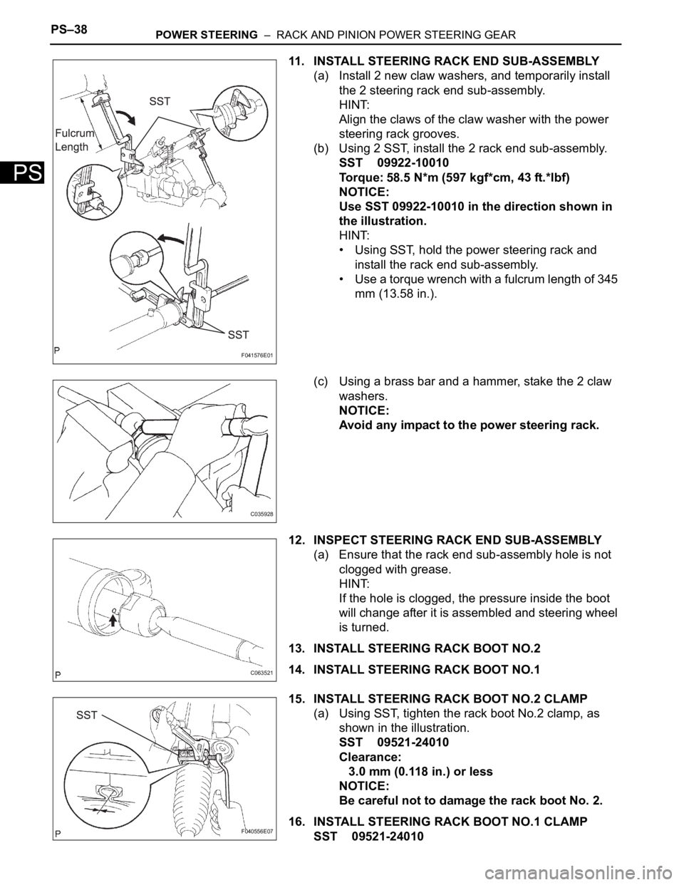
11. INSTALL STEERING RACK END SUB-ASSEMBLY
(a) Install 2 new claw washers, and temporarily install
the 2 steering rack end sub-assembly.
HINT:
Align the claws of the claw washer with the power
steering rack grooves.
(b) Using 2 SST, install the 2 rack end sub-assembly.
SST 09922-10010
Torque: 58.5 N*m (597 kgf*cm, 43 ft.*lbf)
NOTICE:
Use SST 09922-10010 in the direction shown in
the illustration.
HINT:
• Using SST, hold the power steering rack and
install the rack end sub-assembly.
• Use a torque wrench with a fulcrum length of 345
mm (13.58 in.).
(c) Using a brass bar and a hammer, stake the 2 claw
washers.
NOTICE:
Avoid any impact to the power steering rack.
12. INSPECT STEERING RACK END SUB-ASSEMBLY
(a) Ensure that the rack end sub-assembly hole is not
clogged with grease.
HINT:
If the hole is clogged, the pressure inside the boot
will change after it is assembled and steering wheel
is turned.
13. INSTALL STEERING RACK BOOT NO.2
14. INSTALL STEERING RACK BOOT NO.1
15. INSTALL STEERING RACK BOOT NO.2 CLAMP
(a) Using SST, tighten the rack boot No.2 clamp, as
shown in the illustration.
SST 09521-24010
Clearance:
3.0 mm (0.118 in.) or less
NOTICE:
Be careful not to damage the rack boot No. 2.
16. INSTALL STEERING RACK BOOT NO.1 CLAMP
SST 09521-24010
F041576E01
C035928
C063521
F040556E07
Page 2750 of 3000

POWER STEERING – RACK AND PINION POWER STEERING GEARPS–39
PS
HINT:
Perform the same procedure on the other side.
17. INSTALL STEERING RACK BOOT CLIP
(a) Using pliers, install the 2 rack boot clips.
18. INSTALL TIE ROD ASSEMBLY LH
(a) Screw the lock nut and tie rod assembly onto the
rack end sub-assembly until the matchmarks are
aligned.
HINT:
After adjusting toe-in, torque the lock nut.
19. INSTALL TIE ROD ASSEMBLY RH
HINT:
Perform the same procedure on the other side.
20. INSTALL STEERING LEFT TURN PRESSURE TUBE
(a) Coat 2 new O-rings with power steering fluid and
install them onto the left turn pressure tube.
(b) Using SST, install the left turn pressure tube onto
the power steering gear assembly.
SST 09023-38201
Torque: 11.5 N*m (117 kgf*cm, 8 ft.*lbf)
HINT:
• Use a torque wrench with a fulcrum length of 345
mm (13.58 in.).
• This torque value is effective when SST is
parallel to the torque wrench.
21. INSTALL STEERING RIGHT TURN PRESSURE TUBE
SST 09023-38201
HINT:
Perform the same procedure on the other side.
22. INSTALL RETURN TUBE NO.2
(a) Using SST, install the return tube No. 2.
SST 09023-12701
Torque: 22.5 N*m (229 kgf*cm, 17 ft.*lbf)
HINT:
Use a torque wrench with a fulcrum length of 345
mm (13.58 in.).
INSTALLATION
1. INSTALL RACK & PINION POWER STEERING GEAR
ASSEMBLY
(a) Install the power steering gear assembly with the 2
bolts and nuts.
Torque: 70 N*m (714 kgf*cm, 52 ft.*lbf)
D029981E02
D030601E01
D029979
Page 2751 of 3000
PS–40POWER STEERING – RACK AND PINION POWER STEERING GEAR
PS
2. CONNECT PRESSURE FEED TUBE ASSEMBLY
(a) Connect the pressure feed tube assembly to the
power steering gear assembly.
(b) Install the clip.
(c) Using SST, connect the return tube assembly to the
power steering gear assembly.
SST 09023-12701
Torque: 22.5 N*m (229 kgf*cm, 17 ft.*lbf)
HINT:
• Use a torque wrench with a fulcrum length of 300
mm (11.81 in.).
• This torque value is effective when SST is
parallel to the torque wrench.
(d) Install the tube clamp with the bolt.
Torque: 9.8 N*m (100 kgf*cm, 87 in.*lbf)
(e) Install the tube clamp with the nut.
Torque: 9.8 N*m (100 kgf*cm, 87 in.*lbf)
D029970
D029977E01
D029974
D029975