Page 2099 of 3000
DS–24DRIVE SHAFT – REAR DRIVE SHAFT (for 4WD)
DS
4. REMOVE REAR DRIVE SHAFT OUTBOARD JOINT
BOOT CLAMP
(a) Using pliers, remove the 2 rear drive shaft outboard
joint boot clamps as shown in the illustration.
5. REMOVE REAR DRIVE SHAFT OUTBOARD JOINT
BOOT
(a) Remove the outboard joint boot from the outboard
joint shaft.
(b) Remove the old grease from the outboard joint.
NOTICE:
Do not disassemble the outboard joint.
INSPECTION
1. INSPECT REAR DRIVE SHAFT ASSEMBLY LH
(a) Check that there is no remarkable play in the radial
direction of the outboard joint.
(b) Check that the inboard joint slides smoothly in the
thrust direction.
(c) Check that there is no remarkable play in the radial
direction of the inboard joint.
(d) Check the boots for damage.
(e) Make sure that the 2 boots are not stretched or
contracted when the drive shaft is at standard
length.
Standard length:
704.8 +- 5.0 mm (27.748 +- 0.20 in.)
G020982
Z012871
Z013445E01
Page 2187 of 3000

SUSPENSION – FRONT WHEEL ALIGNMENTSP–5
SP
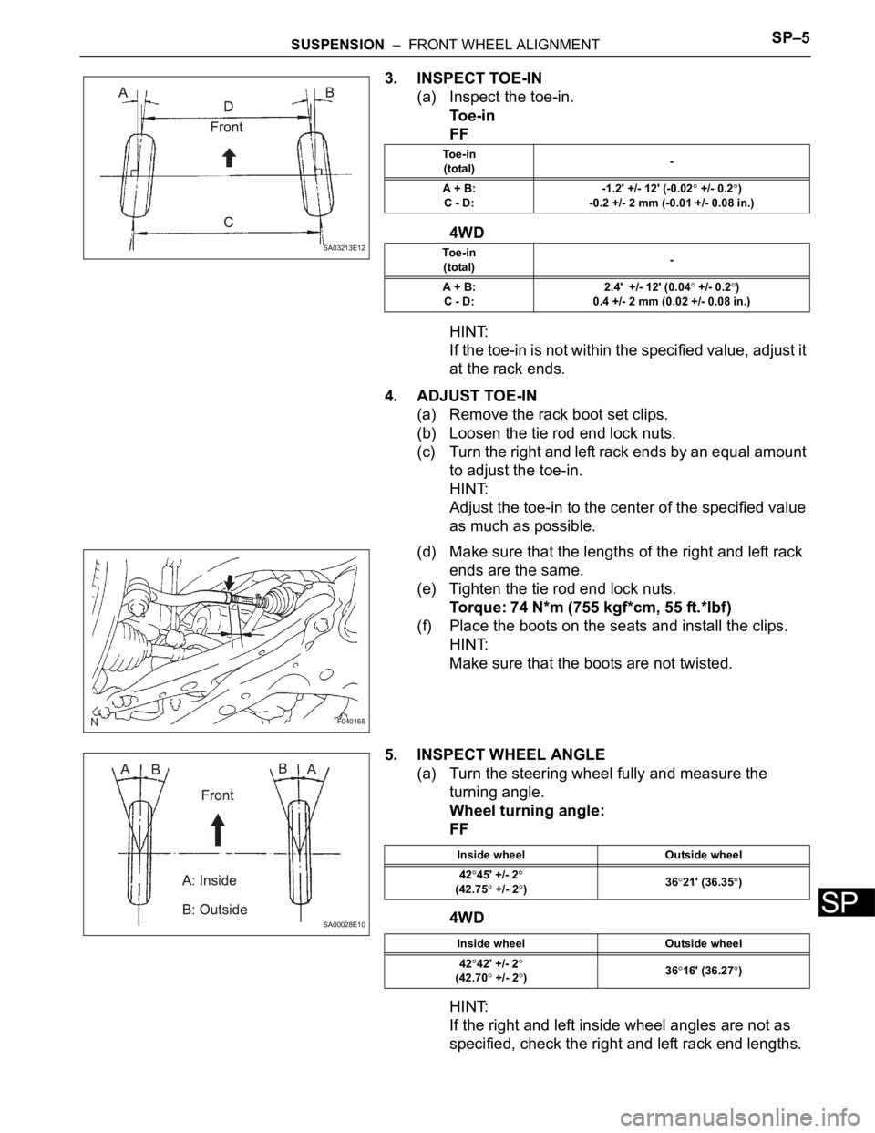
3. INSPECT TOE-IN
(a) Inspect the toe-in.
To e - i n
FF
4WD
HINT:
If the toe-in is not within the specified value, adjust it
at the rack ends.
4. ADJUST TOE-IN
(a) Remove the rack boot set clips.
(b) Loosen the tie rod end lock nuts.
(c) Turn the right and left rack ends by an equal amount
to adjust the toe-in.
HINT:
Adjust the toe-in to the center of the specified value
as much as possible.
(d) Make sure that the lengths of the right and left rack
ends are the same.
(e) Tighten the tie rod end lock nuts.
Torque: 74 N*m (755 kgf*cm, 55 ft.*lbf)
(f) Place the boots on the seats and install the clips.
HINT:
Make sure that the boots are not twisted.
5. INSPECT WHEEL ANGLE
(a) Turn the steering wheel fully and measure the
turning angle.
Wheel turning angle:
FF
4WD
HINT:
If the right and left inside wheel angles are not as
specified, check the right and left rack end lengths.
SA03213E12
To e - i n
(total)-
A + B:
C - D:-1.2' +/- 12' (-0.02
+/- 0.2)
-0.2 +/- 2 mm (-0.01 +/- 0.08 in.)
To e - i n
(total)-
A + B:
C - D:2.4' +/- 12' (0.04
+/- 0.2)
0.4 +/- 2 mm (0.02 +/- 0.08 in.)
F040165
SA00028E10
Inside wheel Outside wheel
42
45' +/- 2(42.75 +/- 2)3621' (36.35)
Inside wheel Outside wheel
42
42' +/- 2
(42.70 +/- 2)3616' (36.27)
Page 2230 of 3000

SUSPENSION – REAR COIL SPRINGSP–47
SP
13. INSTALL SPEED SENSOR REAR LH (for 4WD)
(a) Install the speed sensor rear LH and bolt.
Torque: 8.0 N*m (82 kgf*cm, 71 in.*lbf)
14. INSTALL SPEED SENSOR REAR RH (for 4WD)
HINT:
Install the RH side by same procedures as the LH side.
15. CONNECT SKID CONTROL SENSOR WIRE (for 2WD)
(a) Connect the skid control sensor connector.
(b) Install the bolt and bracket to the rear axle beam
assembly.
Torque: 8.0 N*m (82 kgf*cm, 71 in.*lbf)
HINT:
Connect the RH side by same procedures with the
LH side.
16. INSTALL EXHAUST PIPE ASSEMBLY TAIL
HINT:
• 2WD DRIVE TYPE (See page EX-2)
• 4WD DRIVE TYPE (See page EX-12)
17. BLEED BRAKE LINE
18. INSPECT BRAKE FLUID LEVEL IN RESERVOIR
19. STABILIZE SUSPENSION
(a) Install the rear wheel and jack down the vehicle.
Torque: 103 N*m (1,050 kgf*cm, 76 ft.*lbf)
(b) Bounce the vehicle up and down several times to
stabilize the suspension.
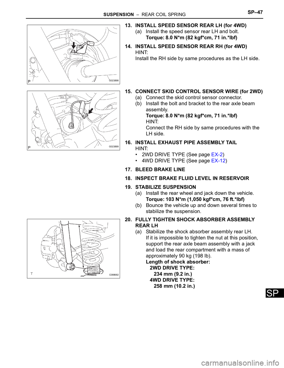
20. FULLY TIGHTEN SHOCK ABSORBER ASSEMBLY
REAR LH
(a) Stabilize the shock absorber assembly rear LH.
If it is impossible to tighten the nut at this position,
support the rear axle beam assembly with a jack
and load the rear compartment with a mass of
approximately 90 kg (198 lb).
Length of shock absorber:
2WD DRIVE TYPE:
234 mm (9.2 in.)
4WD DRIVE TYPE:
258 mm (10.2 in.)
G023898
G023899
C088682
Page 2242 of 3000
SP–54SUSPENSION – REAR SHOCK ABSORBER
SP
4. FULLY TIGHTEN SHOCK ABSORBER ASSEMBLY
REAR LH
(a) Stabilize the shock absorber assembly rear LH.
If it is impossible to tighten the nut at this position,
support the rear axle beam with a jack and load the
rear compartment with a mass of approximately 90
kg (198 lb).
Length of shock absorber:
2WD DRIVE TYPE:
234 mm (9.22 in.)
4WD DRIVE TYPE:
258 mm (10.16 in.)
(b) Fully tighten the nut.
Torque: 115 N*m (1,173 kgf*cm, 85 ft.*lbf)
5. INSPECT REAR WHEEL ALIGNMENT
HINT:
(See page SP-9)
DISPOSAL
1. DISPOSE OF SHOCK ABSORBER ASSEMBLY REAR
LH
(a) Fully extend the shock absorber rod.
(b) Using a drill, make a hole in the cylinder as shown in
the illustration to discharge the gas inside the
cylinder.
CAUTION:
• When drilling, since the fragments may fly
out, work carefully.
• The discharged gas is colorless, odorless
and non-poisonous.
C088682
C088671
C066544E01
Page 2604 of 3000

BRAKE – BRAKE PEDALBR–9
BR
ON-VEHICLE INSPECTION
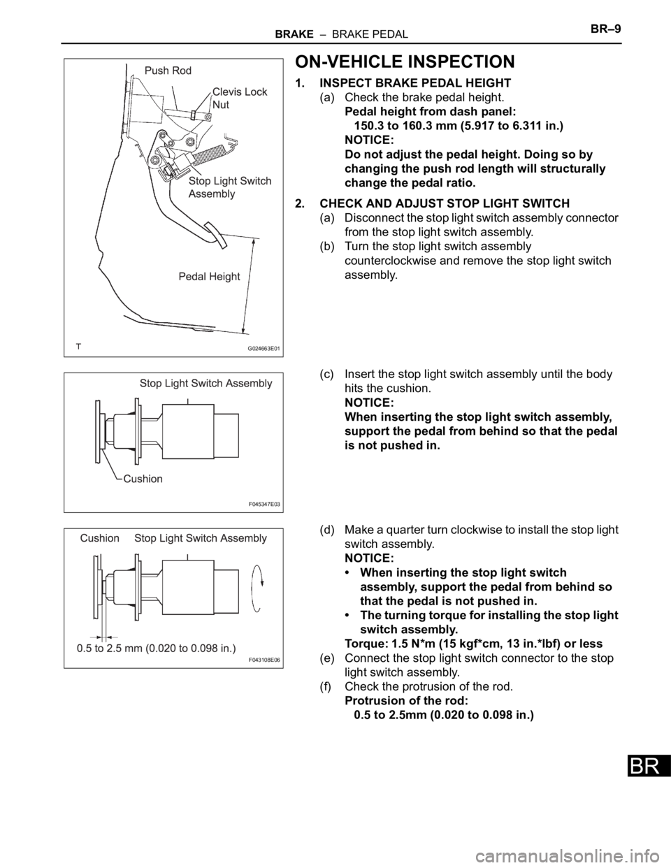
1. INSPECT BRAKE PEDAL HEIGHT
(a) Check the brake pedal height.
Pedal height from dash panel:
150.3 to 160.3 mm (5.917 to 6.311 in.)
NOTICE:
Do not adjust the pedal height. Doing so by
changing the push rod length will structurally
change the pedal ratio.
2. CHECK AND ADJUST STOP LIGHT SWITCH
(a) Disconnect the stop light switch assembly connector
from the stop light switch assembly.
(b) Turn the stop light switch assembly
counterclockwise and remove the stop light switch
assembly.
(c) Insert the stop light switch assembly until the body
hits the cushion.
NOTICE:
When inserting the stop light switch assembly,
support the pedal from behind so that the pedal
is not pushed in.
(d) Make a quarter turn clockwise to install the stop light
switch assembly.
NOTICE:
• When inserting the stop light switch
assembly, support the pedal from behind so
that the pedal is not pushed in.
• The turning torque for installing the stop light
switch assembly.
Torque: 1.5 N*m (15 kgf*cm, 13 in.*lbf) or less
(e) Connect the stop light switch connector to the stop
light switch assembly.
(f) Check the protrusion of the rod.
Protrusion of the rod:
0.5 to 2.5mm (0.020 to 0.098 in.)
G024663E01
F045347E03
F043108E06
Page 2690 of 3000
POWER STEERING – VANE PUMPPS–19
PS
INSTALLATION
1. INSTALL VANE PUMP ASSEMBLY
(a) Temporarily install the bolt to the vane pump
assembly.
(b) Install the vane pump assembly.
(c) Temporarily install the bolt (B).
(d) Using SST, tighten the 2 bolts.
SST 09249-63010
Torque: Without SST
43 N*m (439 kgf*cm, 32 ft.*lbf)
With SST
29 N*m (294 kgf*cm, 21 ft.*lbf)
NOTICE:
• Use a torque wrench with a fulcrum length of
300 mm (11.81 in.).
• This torque value is accurate when SST is
parallel to the torque wrench.
2. CONNECT POWER STEERING FLUID PRESSURE
SWITCH CONNECTOR
(a) Connect the connector to the power steering fluid
pressure switch.
3. CONNECT PRESSURE FEED TUBE ASSEMBLY
(a) Install a new gasket to the pressure feed tube
assembly.
C135238
C159000E01
C161547
Page 2705 of 3000
POWER STEERING – RACK AND PINION POWER STEERING GEARPS–37
PS
(i) Using SST, hold the rack guide spring cap and using
another SST, torque the rack guide spring cap nut.
SST 09616-00011, 09922-10010
Torque: 48 N*m (489 kgf*cm, 35 ft.*lbf)
NOTICE:
Use SST 09922-10010 in the direction shown in
the illustration.
HINT:
Use a torque wrench with a fulcrum length of 345
mm (13.58 in.).
(j) Precheck the total preload.
Torque: Preload (turning)
1.2 to 1.5 N*m (12.2 to 15.3 kgf*cm, 10.6
to 13.3 in.*lbf)
(k) Remove the RH and LH steering rack ends sub-
assembly.
(l) Apply MP grease to the control valve, as shown in
the illustration.
(m) Wind vinyl tape around the serrated part of the
control valve.
(n) Install the dust cover onto the control valve housing.
F041518E01
F040555E08
F040538E10
Page 2706 of 3000

PS–38POWER STEERING – RACK AND PINION POWER STEERING GEAR
PS
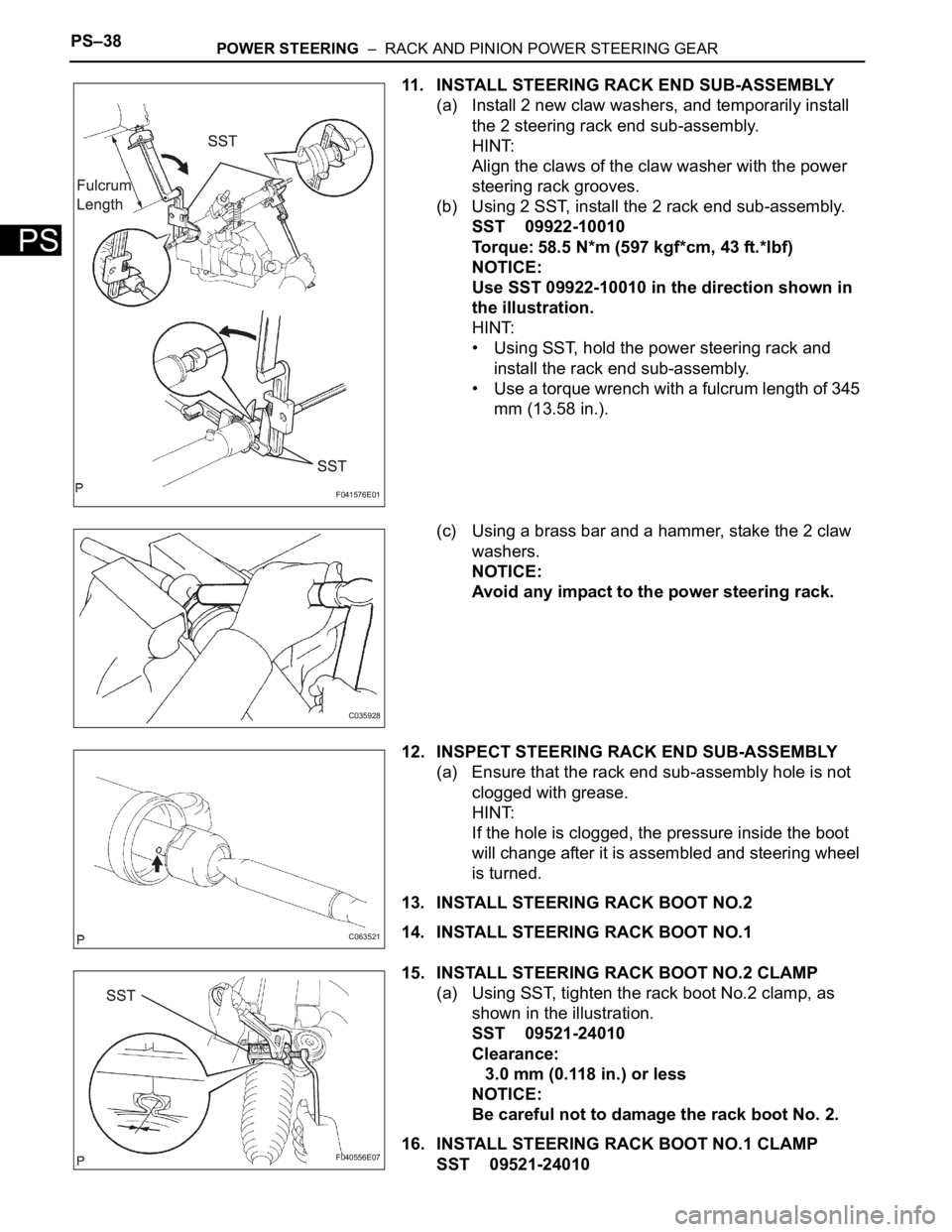
11. INSTALL STEERING RACK END SUB-ASSEMBLY
(a) Install 2 new claw washers, and temporarily install
the 2 steering rack end sub-assembly.
HINT:
Align the claws of the claw washer with the power
steering rack grooves.
(b) Using 2 SST, install the 2 rack end sub-assembly.
SST 09922-10010
Torque: 58.5 N*m (597 kgf*cm, 43 ft.*lbf)
NOTICE:
Use SST 09922-10010 in the direction shown in
the illustration.
HINT:
• Using SST, hold the power steering rack and
install the rack end sub-assembly.
• Use a torque wrench with a fulcrum length of 345
mm (13.58 in.).
(c) Using a brass bar and a hammer, stake the 2 claw
washers.
NOTICE:
Avoid any impact to the power steering rack.
12. INSPECT STEERING RACK END SUB-ASSEMBLY
(a) Ensure that the rack end sub-assembly hole is not
clogged with grease.
HINT:
If the hole is clogged, the pressure inside the boot
will change after it is assembled and steering wheel
is turned.
13. INSTALL STEERING RACK BOOT NO.2
14. INSTALL STEERING RACK BOOT NO.1
15. INSTALL STEERING RACK BOOT NO.2 CLAMP
(a) Using SST, tighten the rack boot No.2 clamp, as
shown in the illustration.
SST 09521-24010
Clearance:
3.0 mm (0.118 in.) or less
NOTICE:
Be careful not to damage the rack boot No. 2.
16. INSTALL STEERING RACK BOOT NO.1 CLAMP
SST 09521-24010
F041576E01
C035928
C063521
F040556E07