Page 1681 of 3000
U151E AUTOMATIC TRANSAXLE – DIFFERENTIAL CASEAX–271
AX
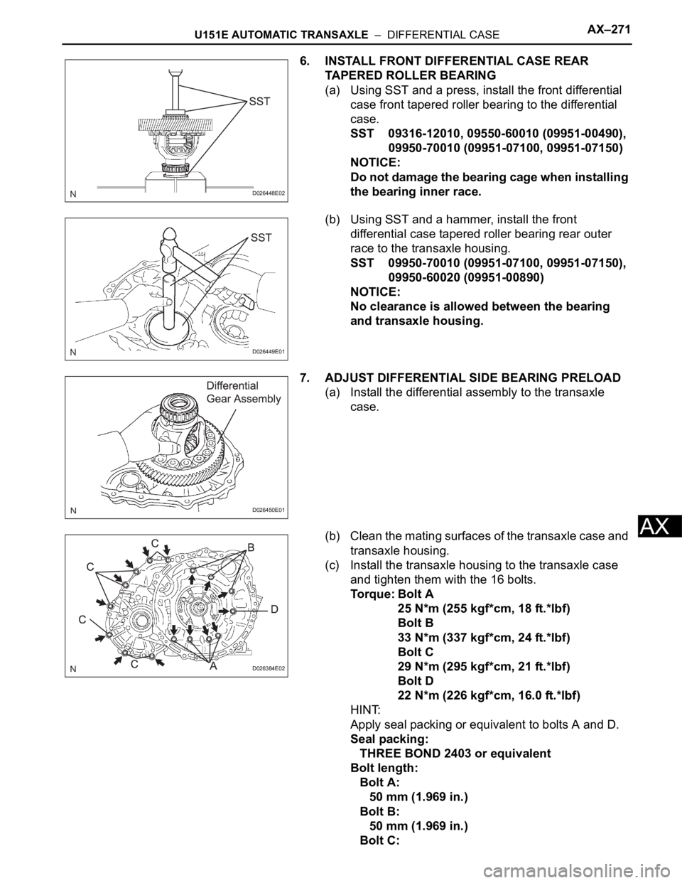
6. INSTALL FRONT DIFFERENTIAL CASE REAR
TAPERED ROLLER BEARING
(a) Using SST and a press, install the front differential
case front tapered roller bearing to the differential
case.
SST 09316-12010, 09550-60010 (09951-00490),
09950-70010 (09951-07100, 09951-07150)
NOTICE:
Do not damage the bearing cage when installing
the bearing inner race.
(b) Using SST and a hammer, install the front
differential case tapered roller bearing rear outer
race to the transaxle housing.
SST 09950-70010 (09951-07100, 09951-07150),
09950-60020 (09951-00890)
NOTICE:
No clearance is allowed between the bearing
and transaxle housing.
7. ADJUST DIFFERENTIAL SIDE BEARING PRELOAD
(a) Install the differential assembly to the transaxle
case.
(b) Clean the mating surfaces of the transaxle case and
transaxle housing.
(c) Install the transaxle housing to the transaxle case
and tighten them with the 16 bolts.
Torque: Bolt A
25 N*m (255 kgf*cm, 18 ft.*lbf)
Bolt B
33 N*m (337 kgf*cm, 24 ft.*lbf)
Bolt C
29 N*m (295 kgf*cm, 21 ft.*lbf)
Bolt D
22 N*m (226 kgf*cm, 16.0 ft.*lbf)
HINT:
Apply seal packing or equivalent to bolts A and D.
Seal packing:
THREE BOND 2403 or equivalent
Bolt length:
Bolt A:
50 mm (1.969 in.)
Bolt B:
50 mm (1.969 in.)
Bolt C:
D026448E02
D026449E01
D026450E01
D026384E02
Page 1826 of 3000
AX–140U151F AUTOMATIC TRANSAXLE – VALVE BODY ASSEMBLY
AX
(f) Install the shift solenoid valve SL3 and SLT to the
valve body assembly.
(g) Install the lock plate to the valve body assembly with
the bolt.
Torque: 6.6 N*m (67 kgf*cm, 58 in.*lbf)
(h) Install the spring and check ball body.
(i) Align the groove of the manual valve with the pin of
the lever.
(j) Install the 17 bolts.
Torque: 11 N*m (110 kgf*cm, 8 ft.*lbf)
NOTICE:
• Push the valve body against the accumulator
piston springs and check ball body to install
the valve body.
• First, temporarily tighten the bolts marked
with (1) in the illustration because they are
positioning bolts.
Bolt length:
Bolt A:
41 mm (1.614 in.)
Bolt B:
57 mm (2.244 in.)
Bolt C:
25 mm (0.984 in.)
2. INSTALL VALVE BODY OIL STRAINER ASSEMBLY
(a) Coat a new O-ring with ATF.
(b) Install the O-ring to the oil strainer.
C089112
C050017
C091933E05
C091932
Page 1877 of 3000
AX–202U151F AUTOMATIC TRANSAXLE – AUTOMATIC TRANSAXLE UNIT
AX
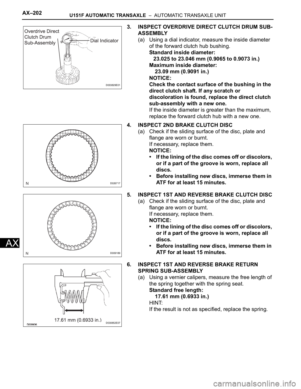
3. INSPECT OVERDRIVE DIRECT CLUTCH DRUM SUB-
ASSEMBLY
(a) Using a dial indicator, measure the inside diameter
of the forward clutch hub bushing.
Standard inside diameter:
23.025 to 23.046 mm (0.9065 to 0.9073 in.)
Maximum inside diameter:
23.09 mm (0.9091 in.)
NOTICE:
Check the contact surface of the bushing in the
direct clutch shaft. If any scratch or
discoloration is found, replace the direct clutch
sub-assembly with a new one.
If the inside diameter is greater than the maximum,
replace the forward clutch hub with a new one.
4. INSPECT 2ND BRAKE CLUTCH DISC
(a) Check if the sliding surface of the disc, plate and
flange are worn or burnt.
If necessary, replace them.
NOTICE:
• If the lining of the disc comes off or discolors,
or if a part of the groove is worn, replace all
discs.
• Before installing new discs, immerse them in
ATF for at least 15 minutes.
5. INSPECT 1ST AND REVERSE BRAKE CLUTCH DISC
(a) Check if the sliding surface of the disc, plate and
flange are worn or burnt.
If necessary, replace them.
NOTICE:
• If the lining of the disc comes off or discolors,
or if a part of the groove is worn, replace all
discs.
• Before installing new discs, immerse them in
ATF for at least 15 minutes.
6. INSPECT 1ST AND REVERSE BRAKE RETURN
SPRING SUB-ASSEMBLY
(a) Using a vernier calipers, measure the free length of
the spring together with the spring seat.
Standard free length:
17.61 mm (0.6933 in.)
HINT:
If the result is not as specified, replace the spring.
D003829E01
D026717
D009189
D030852E07
Page 1878 of 3000
U151F AUTOMATIC TRANSAXLE – AUTOMATIC TRANSAXLE UNITAX–203
AX
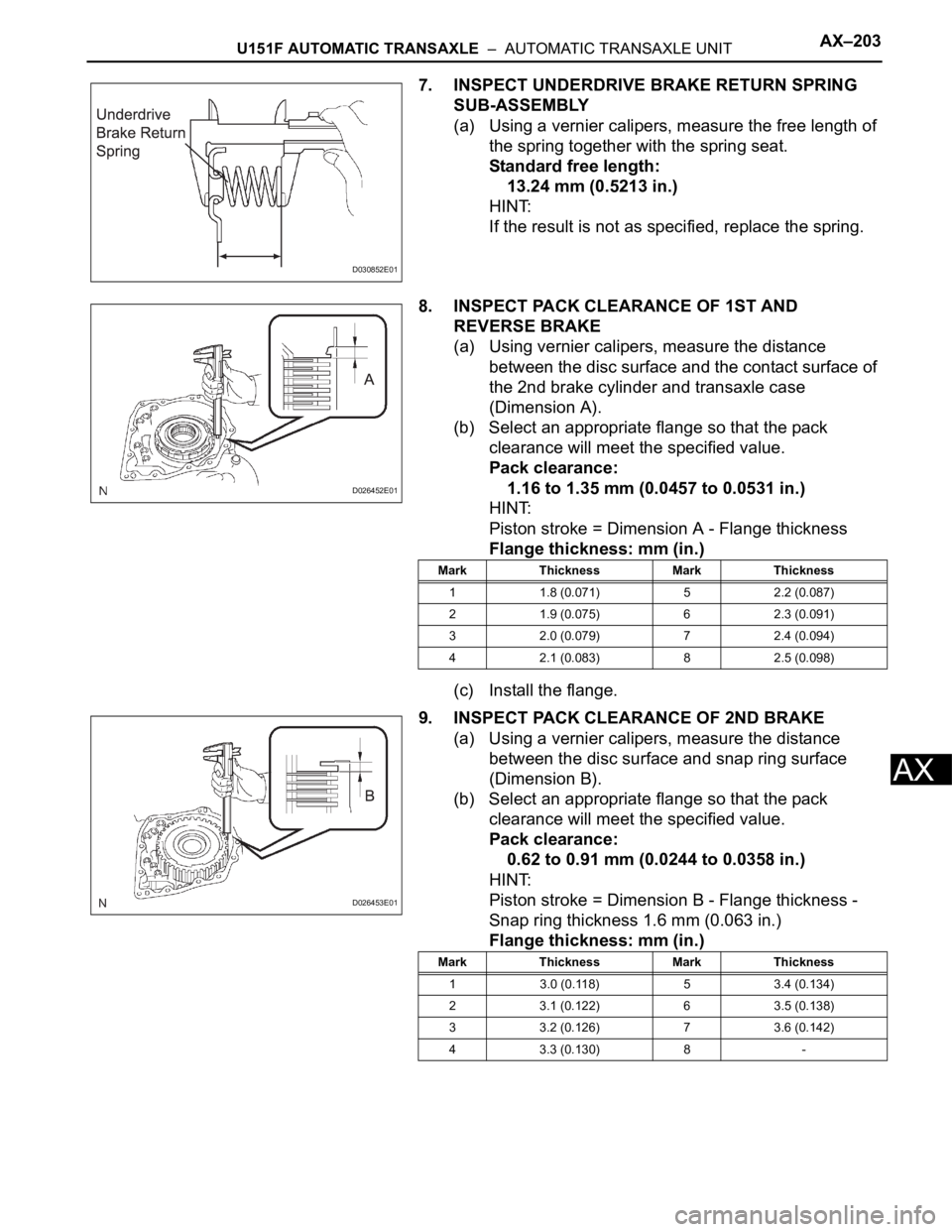
7. INSPECT UNDERDRIVE BRAKE RETURN SPRING
SUB-ASSEMBLY
(a) Using a vernier calipers, measure the free length of
the spring together with the spring seat.
Standard free length:
13.24 mm (0.5213 in.)
HINT:
If the result is not as specified, replace the spring.
8. INSPECT PACK CLEARANCE OF 1ST AND
REVERSE BRAKE
(a) Using vernier calipers, measure the distance
between the disc surface and the contact surface of
the 2nd brake cylinder and transaxle case
(Dimension A).
(b) Select an appropriate flange so that the pack
clearance will meet the specified value.
Pack clearance:
1.16 to 1.35 mm (0.0457 to 0.0531 in.)
HINT:
Piston stroke = Dimension A - Flange thickness
Flange thickness: mm (in.)
(c) Install the flange.
9. INSPECT PACK CLEARANCE OF 2ND BRAKE
(a) Using a vernier calipers, measure the distance
between the disc surface and snap ring surface
(Dimension B).
(b) Select an appropriate flange so that the pack
clearance will meet the specified value.
Pack clearance:
0.62 to 0.91 mm (0.0244 to 0.0358 in.)
HINT:
Piston stroke = Dimension B - Flange thickness -
Snap ring thickness 1.6 mm (0.063 in.)
Flange thickness: mm (in.)
D030852E01
D026452E01
Mark Thickness Mark Thickness
1 1.8 (0.071) 5 2.2 (0.087)
2 1.9 (0.075) 6 2.3 (0.091)
3 2.0 (0.079) 7 2.4 (0.094)
4 2.1 (0.083) 8 2.5 (0.098)
D026453E01
Mark Thickness Mark Thickness
1 3.0 (0.118) 5 3.4 (0.134)
2 3.1 (0.122) 6 3.5 (0.138)
3 3.2 (0.126) 7 3.6 (0.142)
4 3.3 (0.130) 8 -
Page 1895 of 3000
AX–212U151F AUTOMATIC TRANSAXLE – AUTOMATIC TRANSAXLE UNIT
AX
0.51 to 1.02 N*m (5.1 to 10.0 kgf*cm, 4.4 to 8.7
in.*lbf)
Used Bearing:
0.26 to 0.51 N*m (2.7 to 5.2 kgf*cm, 2.3 to 4.5
in.*lbf)
HINT:
Use a torque wrench with a fulcrum length of 160
mm (6.3 in.).
(f) Tighten the nut gradually until the specified turning
torque of tapered roller bearing is measured.
Torque: 350 N*m (3,569 kgf*cm, 258 ft.*lbf)
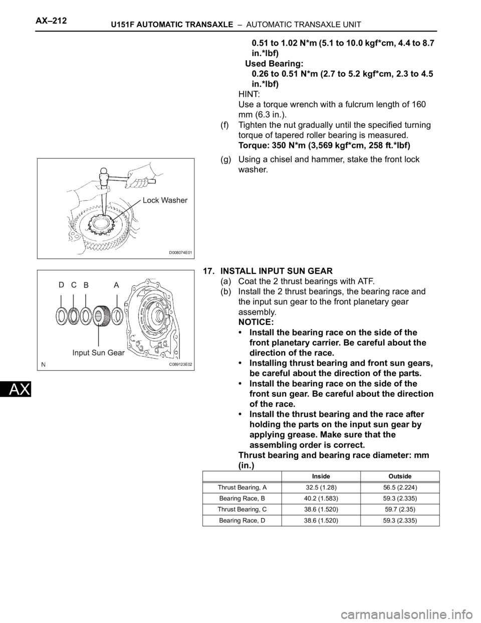
(g) Using a chisel and hammer, stake the front lock
washer.
17. INSTALL INPUT SUN GEAR
(a) Coat the 2 thrust bearings with ATF.
(b) Install the 2 thrust bearings, the bearing race and
the input sun gear to the front planetary gear
assembly.
NOTICE:
• Install the bearing race on the side of the
front planetary carrier. Be careful about the
direction of the race.
• Installing thrust bearing and front sun gears,
be careful about the direction of the parts.
• Install the bearing race on the side of the
front sun gear. Be careful about the direction
of the race.
• Install the thrust bearing and the race after
holding the parts on the input sun gear by
applying grease. Make sure that the
assembling order is correct.
Thrust bearing and bearing race diameter: mm
(in.)
D008074E01
C089123E02
Inside Outside
Thrust Bearing, A 32.5 (1.28) 56.5 (2.224)
Bearing Race, B 40.2 (1.583) 59.3 (2.335)
Thrust Bearing, C 38.6 (1.520) 59.7 (2.35)
Bearing Race, D 38.6 (1.520) 59.3 (2.335)
Page 1909 of 3000
AX–226U151F AUTOMATIC TRANSAXLE – AUTOMATIC TRANSAXLE UNIT
AX
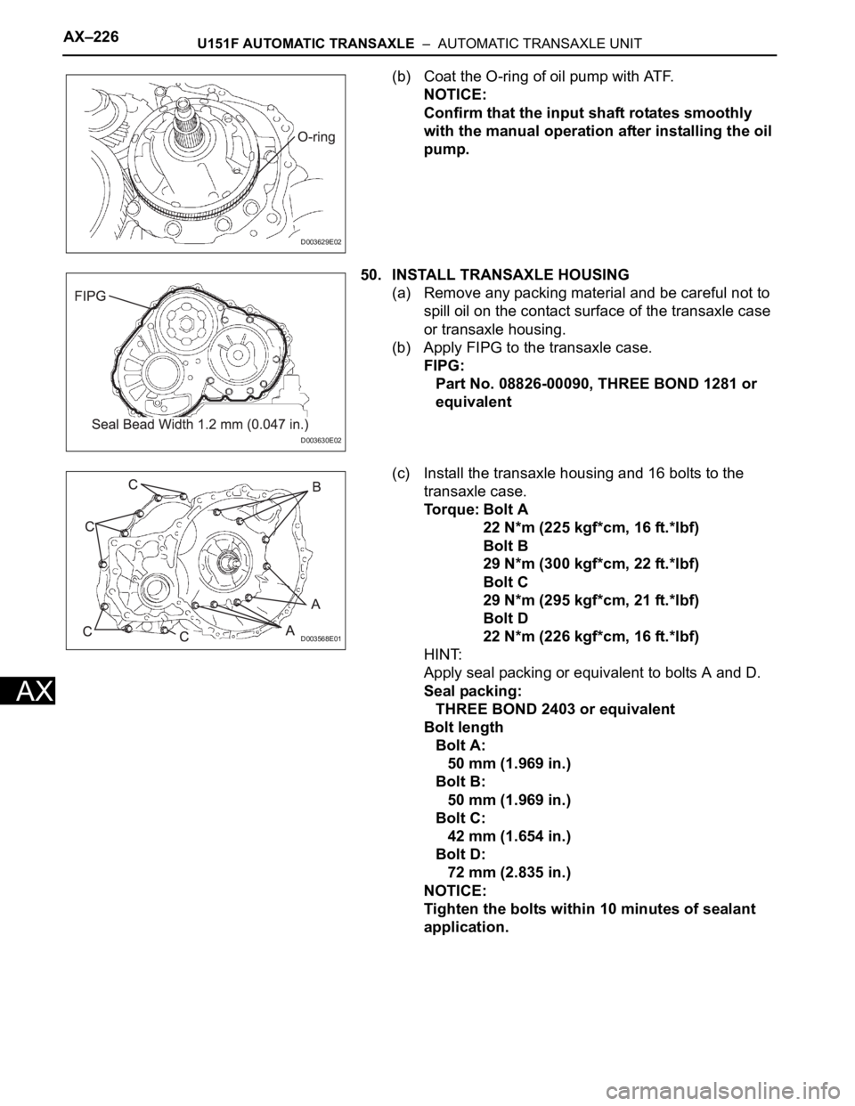
(b) Coat the O-ring of oil pump with ATF.
NOTICE:
Confirm that the input shaft rotates smoothly
with the manual operation after installing the oil
pump.
50. INSTALL TRANSAXLE HOUSING
(a) Remove any packing material and be careful not to
spill oil on the contact surface of the transaxle case
or transaxle housing.
(b) Apply FIPG to the transaxle case.
FIPG:
Part No. 08826-00090, THREE BOND 1281 or
equivalent
(c) Install the transaxle housing and 16 bolts to the
transaxle case.
To r q u e : B o l t A
22 N*m (225 kgf*cm, 16 ft.*lbf)
Bolt B
29 N*m (300 kgf*cm, 22 ft.*lbf)
Bolt C
29 N*m (295 kgf*cm, 21 ft.*lbf)
Bolt D
22 N*m (226 kgf*cm, 16 ft.*lbf)
HINT:
Apply seal packing or equivalent to bolts A and D.
Seal packing:
THREE BOND 2403 or equivalent
Bolt length
Bolt A:
50 mm (1.969 in.)
Bolt B:
50 mm (1.969 in.)
Bolt C:
42 mm (1.654 in.)
Bolt D:
72 mm (2.835 in.)
NOTICE:
Tighten the bolts within 10 minutes of sealant
application.
D003629E02
D003630E02
D003568E01
Page 1911 of 3000
AX–228U151F AUTOMATIC TRANSAXLE – AUTOMATIC TRANSAXLE UNIT
AX
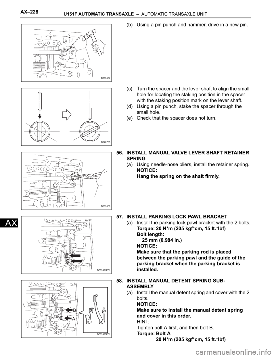
(b) Using a pin punch and hammer, drive in a new pin.
(c) Turn the spacer and the lever shaft to align the small
hole for locating the staking position in the spacer
with the staking position mark on the lever shaft.
(d) Using a pin punch, stake the spacer through the
small hole.
(e) Check that the spacer does not turn.
56. INSTALL MANUAL VALVE LEVER SHAFT RETAINER
SPRING
(a) Using needle-nose pliers, install the retainer spring.
NOTICE:
Hang the spring on the shaft firmly.
57. INSTALL PARKING LOCK PAWL BRACKET
(a) Install the parking lock pawl bracket with the 2 bolts.
Torque: 20 N*m (205 kgf*cm, 15 ft.*lbf)
Bolt length:
25 mm (0.984 in.)
NOTICE:
Make sure that the parking rod is placed
between the parking pawl and the guide of the
parking bracket when the parking bracket is
installed.
58. INSTALL MANUAL DETENT SPRING SUB-
ASSEMBLY
(a) Install the manual detent spring and cover with the 2
bolts.
NOTICE:
Make sure to install the manual detent spring
and cover in this order.
HINT:
Tighten bolt A first, and then bolt B.
To r q u e : B o l t A
20 N*m (205 kgf*cm, 15 ft.*lbf)
D003564
D026765
D003559
D003561E01
D003560E01
Page 1912 of 3000
U151F AUTOMATIC TRANSAXLE – AUTOMATIC TRANSAXLE UNITAX–229
AX
Bolt B
12 N*m (120 kgf*cm, 9 ft.*lbf)
Bolt length:
Bolt A:
27 mm (1.063 in.)
Bolt B:
16 mm (0.630 in.)
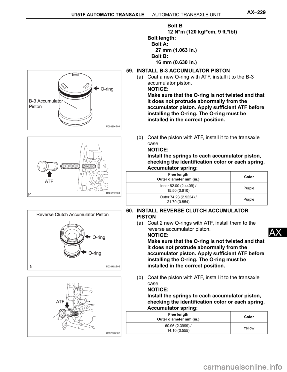
59. INSTALL B-3 ACCUMULATOR PISTON
(a) Coat a new O-ring with ATF, install it to the B-3
accumulator piston.
NOTICE:
Make sure that the O-ring is not twisted and that
it does not protrude abnormally from the
accumulator piston. Apply sufficient ATF before
installing the O-ring. The O-ring must be
installed in the correct position.
(b) Coat the piston with ATF, install it to the transaxle
case.
NOTICE:
Install the springs to each accumulator piston,
checking the identification color or each spring.
Accumulator spring:
60. INSTALL REVERSE CLUTCH ACCUMULATOR
PISTON
(a) Coat 2 new O-rings with ATF, install them to the
reverse accumulator piston.
NOTICE:
Make sure that the O-ring is not twisted and that
it does not protrude abnormally from the
accumulator piston. Apply sufficient ATF before
installing the O-ring. The O-ring must be
installed in the correct position.
(b) Coat the piston with ATF, install it to the transaxle
case.
NOTICE:
Install the springs to each accumulator piston,
checking the identification color or each spring.
Accumulator spring:
D003904E01
D025512E01
Free length
Outer diameter mm (in.)Color
Inner 62.00 (2.4409) /
15.50 (0.610)Purple
Outer 74.23 (2.9224) /
21.70 (0.854)Purple
D026402E05
C092978E02
Free length
Outer diameter mm (in.)Color
60.96 (2.3999) /
14.10 (0.555)Ye l l o w