2007 TOYOTA SIENNA length
[x] Cancel search: lengthPage 1913 of 3000
AX–230U151F AUTOMATIC TRANSAXLE – AUTOMATIC TRANSAXLE UNIT
AX
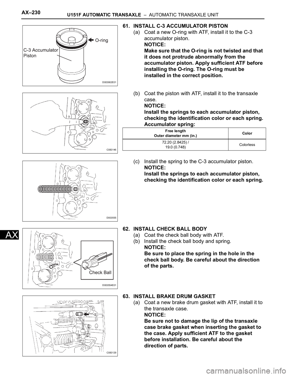
61. INSTALL C-3 ACCUMULATOR PISTON
(a) Coat a new O-ring with ATF, install it to the C-3
accumulator piston.
NOTICE:
Make sure that the O-ring is not twisted and that
it does not protrude abnormally from the
accumulator piston. Apply sufficient ATF before
installing the O-ring. The O-ring must be
installed in the correct position.
(b) Coat the piston with ATF, install it to the transaxle
case.
NOTICE:
Install the springs to each accumulator piston,
checking the identification color or each spring.
Accumulator spring:
(c) Install the spring to the C-3 accumulator piston.
NOTICE:
Install the springs to each accumulator piston,
checking the identification color or each spring.
62. INSTALL CHECK BALL BODY
(a) Coat the check ball body with ATF.
(b) Install the check ball body and spring.
NOTICE:
Be sure to place the spring in the hole in the
check ball body. Be careful about the direction
of the parts.
63. INSTALL BRAKE DRUM GASKET
(a) Coat a new brake drum gasket with ATF, install it to
the transaxle case.
NOTICE:
Be sure not to damage the lip of the transaxle
case brake gasket when inserting the gasket to
the case. Apply sufficient ATF to the gasket
before installation. Be careful about the
direction of parts.
D003902E01
C083146
Free length
Outer diameter mm (in.)Color
72.20 (2.8425) /
19.0 (0.748)Colorless
D003555
D003554E01
C083129
Page 1915 of 3000
AX–232U151F AUTOMATIC TRANSAXLE – AUTOMATIC TRANSAXLE UNIT
AX
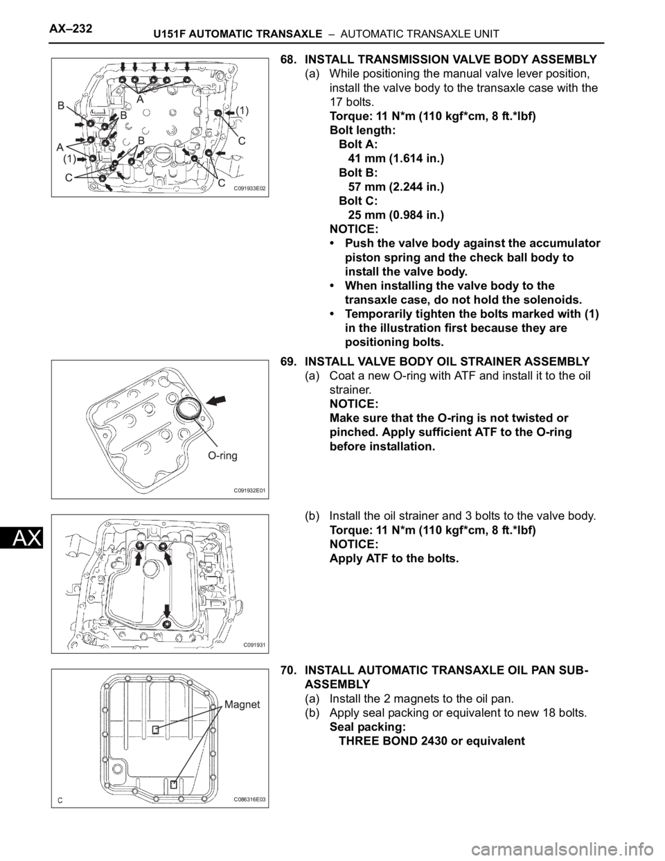
68. INSTALL TRANSMISSION VALVE BODY ASSEMBLY
(a) While positioning the manual valve lever position,
install the valve body to the transaxle case with the
17 bolts.
Torque: 11 N*m (110 kgf*cm, 8 ft.*lbf)
Bolt length:
Bolt A:
41 mm (1.614 in.)
Bolt B:
57 mm (2.244 in.)
Bolt C:
25 mm (0.984 in.)
NOTICE:
• Push the valve body against the accumulator
piston spring and the check ball body to
install the valve body.
• When installing the valve body to the
transaxle case, do not hold the solenoids.
• Temporarily tighten the bolts marked with (1)
in the illustration first because they are
positioning bolts.
69. INSTALL VALVE BODY OIL STRAINER ASSEMBLY
(a) Coat a new O-ring with ATF and install it to the oil
strainer.
NOTICE:
Make sure that the O-ring is not twisted or
pinched. Apply sufficient ATF to the O-ring
before installation.
(b) Install the oil strainer and 3 bolts to the valve body.
Torque: 11 N*m (110 kgf*cm, 8 ft.*lbf)
NOTICE:
Apply ATF to the bolts.
70. INSTALL AUTOMATIC TRANSAXLE OIL PAN SUB-
ASSEMBLY
(a) Install the 2 magnets to the oil pan.
(b) Apply seal packing or equivalent to new 18 bolts.
Seal packing:
THREE BOND 2430 or equivalent
C091933E02
C091932E01
C091931
C086316E03
Page 1920 of 3000
U151F AUTOMATIC TRANSAXLE – TORQUE CONVERTER CLUTCH AND DRIVE PLATEAX–173
AX
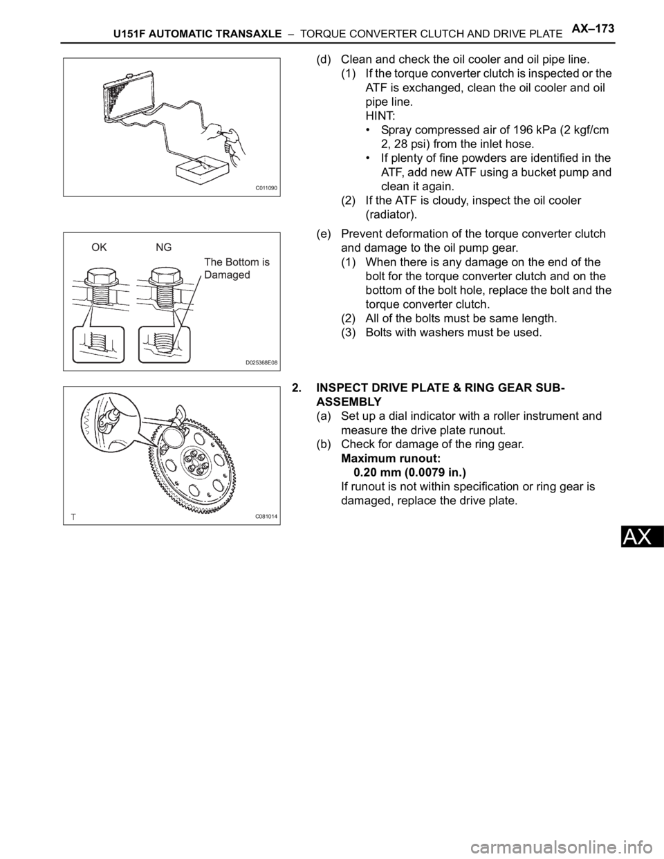
(d) Clean and check the oil cooler and oil pipe line.
(1) If the torque converter clutch is inspected or the
ATF is exchanged, clean the oil cooler and oil
pipe line.
HINT:
• Spray compressed air of 196 kPa (2 kgf/cm
2, 28 psi) from the inlet hose.
• If plenty of fine powders are identified in the
ATF, add new ATF using a bucket pump and
clean it again.
(2) If the ATF is cloudy, inspect the oil cooler
(radiator).
(e) Prevent deformation of the torque converter clutch
and damage to the oil pump gear.
(1) When there is any damage on the end of the
bolt for the torque converter clutch and on the
bottom of the bolt hole, replace the bolt and the
torque converter clutch.
(2) All of the bolts must be same length.
(3) Bolts with washers must be used.
2. INSPECT DRIVE PLATE & RING GEAR SUB-
ASSEMBLY
(a) Set up a dial indicator with a roller instrument and
measure the drive plate runout.
(b) Check for damage of the ring gear.
Maximum runout:
0.20 mm (0.0079 in.)
If runout is not within specification or ring gear is
damaged, replace the drive plate.
C011090
D025368E08
C081014
Page 1943 of 3000
AX–202U151F AUTOMATIC TRANSAXLE – AUTOMATIC TRANSAXLE UNIT
AX
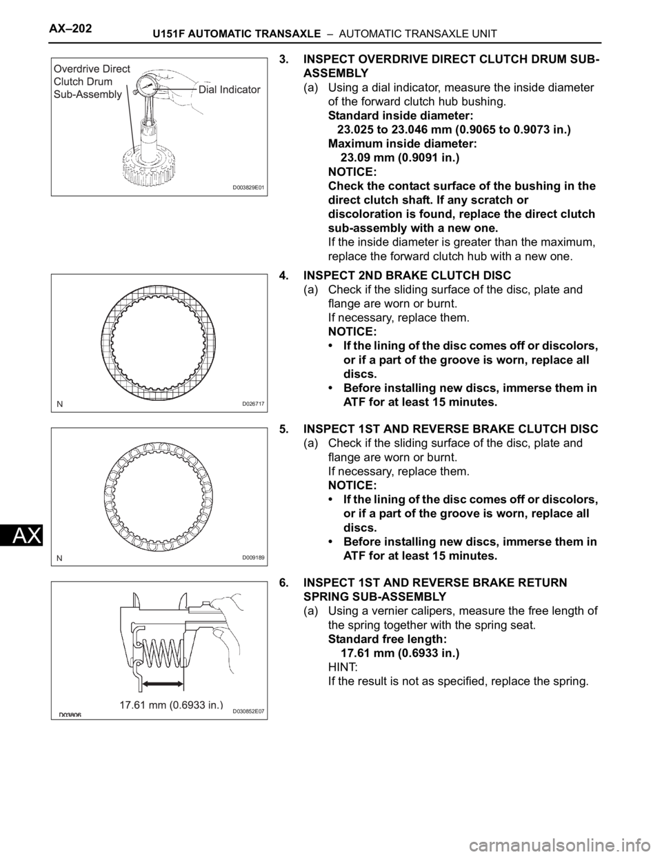
3. INSPECT OVERDRIVE DIRECT CLUTCH DRUM SUB-
ASSEMBLY
(a) Using a dial indicator, measure the inside diameter
of the forward clutch hub bushing.
Standard inside diameter:
23.025 to 23.046 mm (0.9065 to 0.9073 in.)
Maximum inside diameter:
23.09 mm (0.9091 in.)
NOTICE:
Check the contact surface of the bushing in the
direct clutch shaft. If any scratch or
discoloration is found, replace the direct clutch
sub-assembly with a new one.
If the inside diameter is greater than the maximum,
replace the forward clutch hub with a new one.
4. INSPECT 2ND BRAKE CLUTCH DISC
(a) Check if the sliding surface of the disc, plate and
flange are worn or burnt.
If necessary, replace them.
NOTICE:
• If the lining of the disc comes off or discolors,
or if a part of the groove is worn, replace all
discs.
• Before installing new discs, immerse them in
ATF for at least 15 minutes.
5. INSPECT 1ST AND REVERSE BRAKE CLUTCH DISC
(a) Check if the sliding surface of the disc, plate and
flange are worn or burnt.
If necessary, replace them.
NOTICE:
• If the lining of the disc comes off or discolors,
or if a part of the groove is worn, replace all
discs.
• Before installing new discs, immerse them in
ATF for at least 15 minutes.
6. INSPECT 1ST AND REVERSE BRAKE RETURN
SPRING SUB-ASSEMBLY
(a) Using a vernier calipers, measure the free length of
the spring together with the spring seat.
Standard free length:
17.61 mm (0.6933 in.)
HINT:
If the result is not as specified, replace the spring.
D003829E01
D026717
D009189
D030852E07
Page 1944 of 3000
U151F AUTOMATIC TRANSAXLE – AUTOMATIC TRANSAXLE UNITAX–203
AX
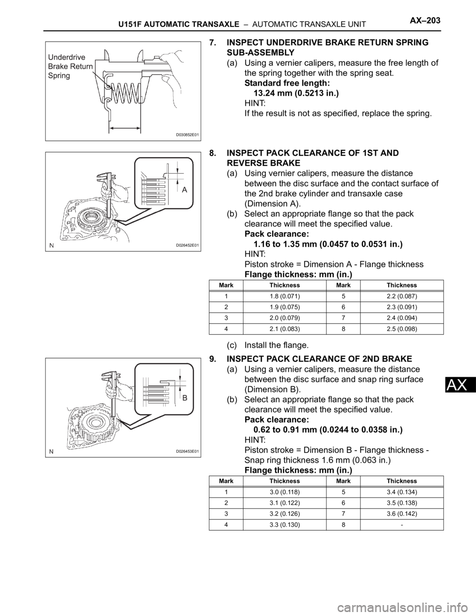
7. INSPECT UNDERDRIVE BRAKE RETURN SPRING
SUB-ASSEMBLY
(a) Using a vernier calipers, measure the free length of
the spring together with the spring seat.
Standard free length:
13.24 mm (0.5213 in.)
HINT:
If the result is not as specified, replace the spring.
8. INSPECT PACK CLEARANCE OF 1ST AND
REVERSE BRAKE
(a) Using vernier calipers, measure the distance
between the disc surface and the contact surface of
the 2nd brake cylinder and transaxle case
(Dimension A).
(b) Select an appropriate flange so that the pack
clearance will meet the specified value.
Pack clearance:
1.16 to 1.35 mm (0.0457 to 0.0531 in.)
HINT:
Piston stroke = Dimension A - Flange thickness
Flange thickness: mm (in.)
(c) Install the flange.
9. INSPECT PACK CLEARANCE OF 2ND BRAKE
(a) Using a vernier calipers, measure the distance
between the disc surface and snap ring surface
(Dimension B).
(b) Select an appropriate flange so that the pack
clearance will meet the specified value.
Pack clearance:
0.62 to 0.91 mm (0.0244 to 0.0358 in.)
HINT:
Piston stroke = Dimension B - Flange thickness -
Snap ring thickness 1.6 mm (0.063 in.)
Flange thickness: mm (in.)
D030852E01
D026452E01
Mark Thickness Mark Thickness
1 1.8 (0.071) 5 2.2 (0.087)
2 1.9 (0.075) 6 2.3 (0.091)
3 2.0 (0.079) 7 2.4 (0.094)
4 2.1 (0.083) 8 2.5 (0.098)
D026453E01
Mark Thickness Mark Thickness
1 3.0 (0.118) 5 3.4 (0.134)
2 3.1 (0.122) 6 3.5 (0.138)
3 3.2 (0.126) 7 3.6 (0.142)
4 3.3 (0.130) 8 -
Page 1947 of 3000
U151F AUTOMATIC TRANSAXLE – FORWARD CLUTCHAX–247
AX
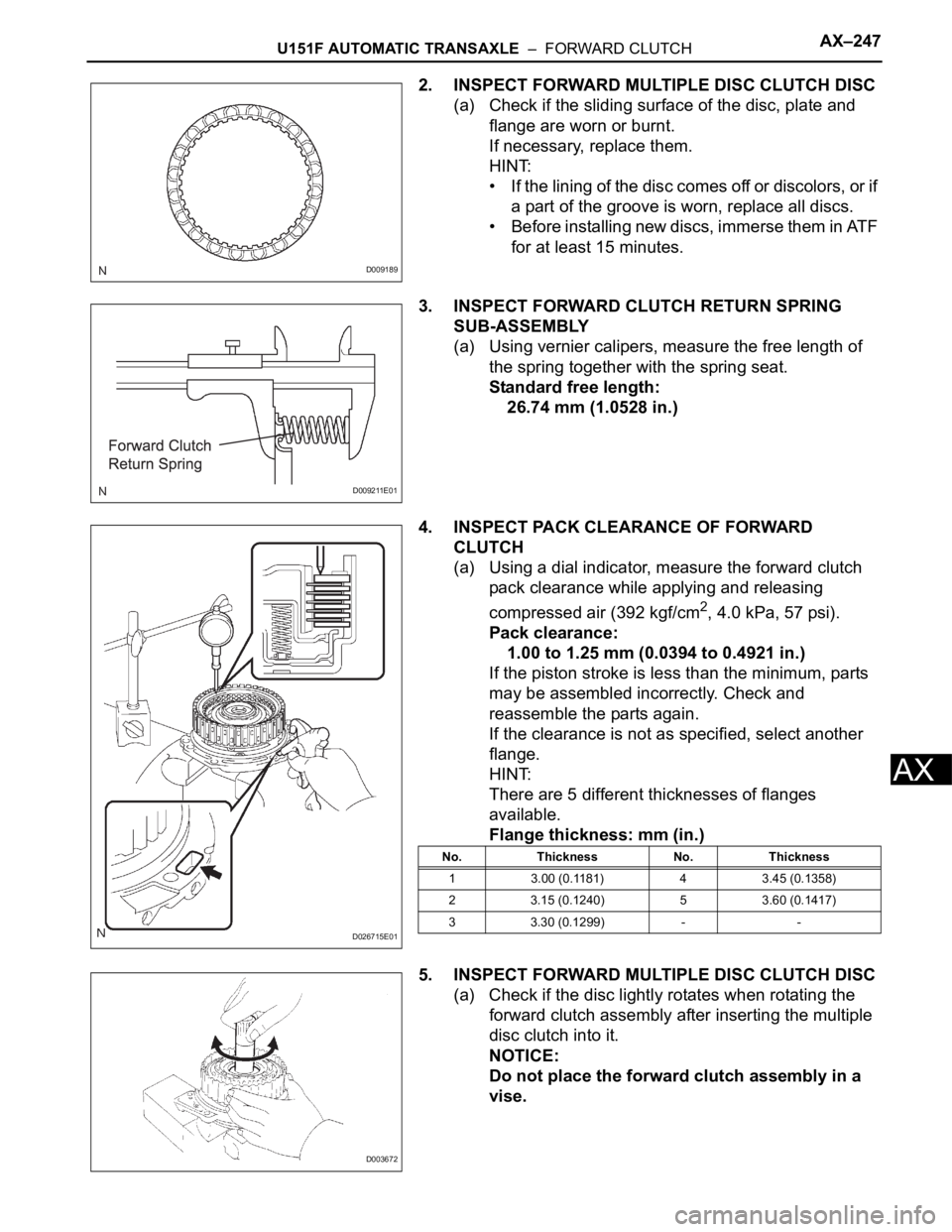
2. INSPECT FORWARD MULTIPLE DISC CLUTCH DISC
(a) Check if the sliding surface of the disc, plate and
flange are worn or burnt.
If necessary, replace them.
HINT:
• If the lining of the disc comes off or discolors, or if
a part of the groove is worn, replace all discs.
• Before installing new discs, immerse them in ATF
for at least 15 minutes.
3. INSPECT FORWARD CLUTCH RETURN SPRING
SUB-ASSEMBLY
(a) Using vernier calipers, measure the free length of
the spring together with the spring seat.
Standard free length:
26.74 mm (1.0528 in.)
4. INSPECT PACK CLEARANCE OF FORWARD
CLUTCH
(a) Using a dial indicator, measure the forward clutch
pack clearance while applying and releasing
compressed air (392 kgf/cm
2, 4.0 kPa, 57 psi).
Pack clearance:
1.00 to 1.25 mm (0.0394 to 0.4921 in.)
If the piston stroke is less than the minimum, parts
may be assembled incorrectly. Check and
reassemble the parts again.
If the clearance is not as specified, select another
flange.
HINT:
There are 5 different thicknesses of flanges
available.
Flange thickness: mm (in.)
5. INSPECT FORWARD MULTIPLE DISC CLUTCH DISC
(a) Check if the disc lightly rotates when rotating the
forward clutch assembly after inserting the multiple
disc clutch into it.
NOTICE:
Do not place the forward clutch assembly in a
vise.
D009189
D009211E01
D026715E01
No. Thickness No. Thickness
1 3.00 (0.1181) 4 3.45 (0.1358)
2 3.15 (0.1240) 5 3.60 (0.1417)
3 3.30 (0.1299) - -
D003672
Page 1960 of 3000
U151F AUTOMATIC TRANSAXLE – FORWARD CLUTCHAX–247
AX
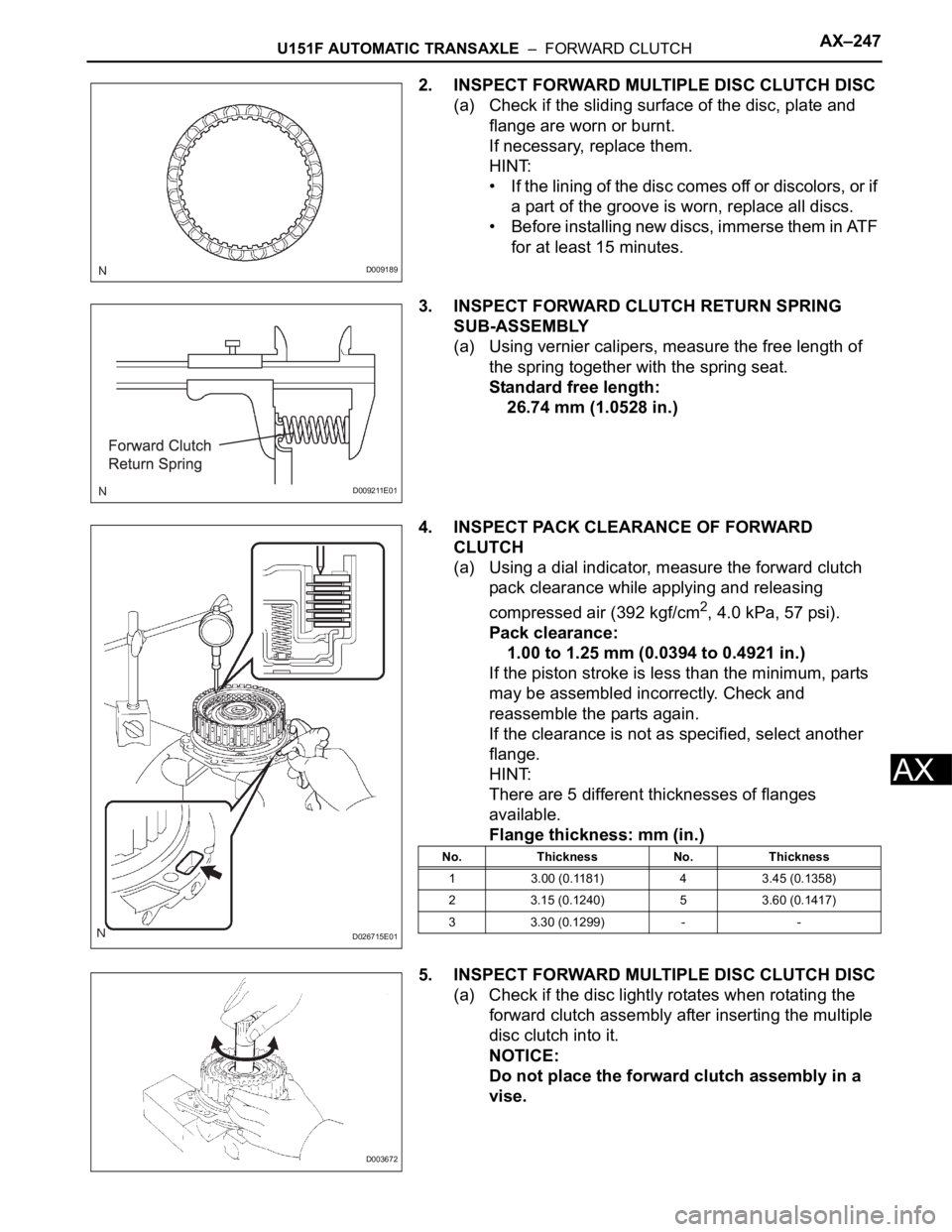
2. INSPECT FORWARD MULTIPLE DISC CLUTCH DISC
(a) Check if the sliding surface of the disc, plate and
flange are worn or burnt.
If necessary, replace them.
HINT:
• If the lining of the disc comes off or discolors, or if
a part of the groove is worn, replace all discs.
• Before installing new discs, immerse them in ATF
for at least 15 minutes.
3. INSPECT FORWARD CLUTCH RETURN SPRING
SUB-ASSEMBLY
(a) Using vernier calipers, measure the free length of
the spring together with the spring seat.
Standard free length:
26.74 mm (1.0528 in.)
4. INSPECT PACK CLEARANCE OF FORWARD
CLUTCH
(a) Using a dial indicator, measure the forward clutch
pack clearance while applying and releasing
compressed air (392 kgf/cm
2, 4.0 kPa, 57 psi).
Pack clearance:
1.00 to 1.25 mm (0.0394 to 0.4921 in.)
If the piston stroke is less than the minimum, parts
may be assembled incorrectly. Check and
reassemble the parts again.
If the clearance is not as specified, select another
flange.
HINT:
There are 5 different thicknesses of flanges
available.
Flange thickness: mm (in.)
5. INSPECT FORWARD MULTIPLE DISC CLUTCH DISC
(a) Check if the disc lightly rotates when rotating the
forward clutch assembly after inserting the multiple
disc clutch into it.
NOTICE:
Do not place the forward clutch assembly in a
vise.
D009189
D009211E01
D026715E01
No. Thickness No. Thickness
1 3.00 (0.1181) 4 3.45 (0.1358)
2 3.15 (0.1240) 5 3.60 (0.1417)
3 3.30 (0.1299) - -
D003672
Page 1964 of 3000
U151F AUTOMATIC TRANSAXLE – DIFFERENTIAL CASEAX–279
AX
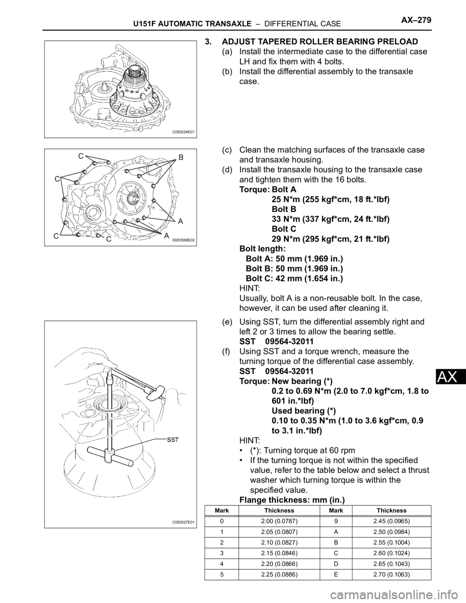
3. ADJUST TAPERED ROLLER BEARING PRELOAD
(a) Install the intermediate case to the differential case
LH and fix them with 4 bolts.
(b) Install the differential assembly to the transaxle
case.
(c) Clean the matching surfaces of the transaxle case
and transaxle housing.
(d) Install the transaxle housing to the transaxle case
and tighten them with the 16 bolts.
Torque: Bolt A
25 N*m (255 kgf*cm, 18 ft.*lbf)
Bolt B
33 N*m (337 kgf*cm, 24 ft.*lbf)
Bolt C
29 N*m (295 kgf*cm, 21 ft.*lbf)
Bolt length:
Bolt A: 50 mm (1.969 in.)
Bolt B: 50 mm (1.969 in.)
Bolt C: 42 mm (1.654 in.)
HINT:
Usually, bolt A is a non-reusable bolt. In the case,
however, it can be used after cleaning it.
(e) Using SST, turn the differential assembly right and
left 2 or 3 times to allow the bearing settle.
SST 09564-32011
(f) Using SST and a torque wrench, measure the
turning torque of the differential case assembly.
SST 09564-32011
Torque: New bearing (*)
0.2 to 0.69 N*m (2.0 to 7.0 kgf*cm, 1.8 to
601 in.*lbf)
Used bearing (*)
0.10 to 0.35 N*m (1.0 to 3.6 kgf*cm, 0.9
to 3.1 in.*lbf)
HINT:
• (*): Turning torque at 60 rpm
• If the turning torque is not within the specified
value, refer to the table below and select a thrust
washer which turning torque is within the
specified value.
Flange thickness: mm (in.)
C050224E01
D003568E02
C050227E01
Mark Thickness Mark Thickness
0 2.00 (0.0787) 9 2.45 (0.0965)
1 2.05 (0.0807) A 2.50 (0.0984)
2 2.10 (0.0827) B 2.55 (0.1004)
3 2.15 (0.0846) C 2.60 (0.1024)
4 2.20 (0.0866) D 2.65 (0.1043)
5 2.25 (0.0886) E 2.70 (0.1063)