Page 1976 of 3000
AX–254U151F AUTOMATIC TRANSAXLE – DIRECT CLUTCH
AX
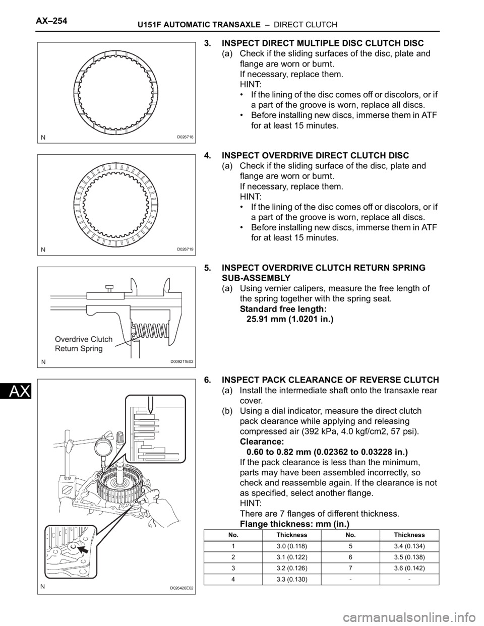
3. INSPECT DIRECT MULTIPLE DISC CLUTCH DISC
(a) Check if the sliding surfaces of the disc, plate and
flange are worn or burnt.
If necessary, replace them.
HINT:
• If the lining of the disc comes off or discolors, or if
a part of the groove is worn, replace all discs.
• Before installing new discs, immerse them in ATF
for at least 15 minutes.
4. INSPECT OVERDRIVE DIRECT CLUTCH DISC
(a) Check if the sliding surface of the disc, plate and
flange are worn or burnt.
If necessary, replace them.
HINT:
• If the lining of the disc comes off or discolors, or if
a part of the groove is worn, replace all discs.
• Before installing new discs, immerse them in ATF
for at least 15 minutes.
5. INSPECT OVERDRIVE CLUTCH RETURN SPRING
SUB-ASSEMBLY
(a) Using vernier calipers, measure the free length of
the spring together with the spring seat.
Standard free length:
25.91 mm (1.0201 in.)
6. INSPECT PACK CLEARANCE OF REVERSE CLUTCH
(a) Install the intermediate shaft onto the transaxle rear
cover.
(b) Using a dial indicator, measure the direct clutch
pack clearance while applying and releasing
compressed air (392 kPa, 4.0 kgf/cm2, 57 psi).
Clearance:
0.60 to 0.82 mm (0.02362 to 0.03228 in.)
If the pack clearance is less than the minimum,
parts may have been assembled incorrectly, so
check and reassemble again. If the clearance is not
as specified, select another flange.
HINT:
There are 7 flanges of different thickness.
Flange thickness: mm (in.)
D026718
D026719
D009211E02
D026426E02
No. Thickness No. Thickness
1 3.0 (0.118) 5 3.4 (0.134)
2 3.1 (0.122) 6 3.5 (0.138)
3 3.2 (0.126) 7 3.6 (0.142)
4 3.3 (0.130) - -
Page 1983 of 3000
U151F AUTOMATIC TRANSAXLE – UNDERDRIVE PLANETARY GEARAX–261
AX
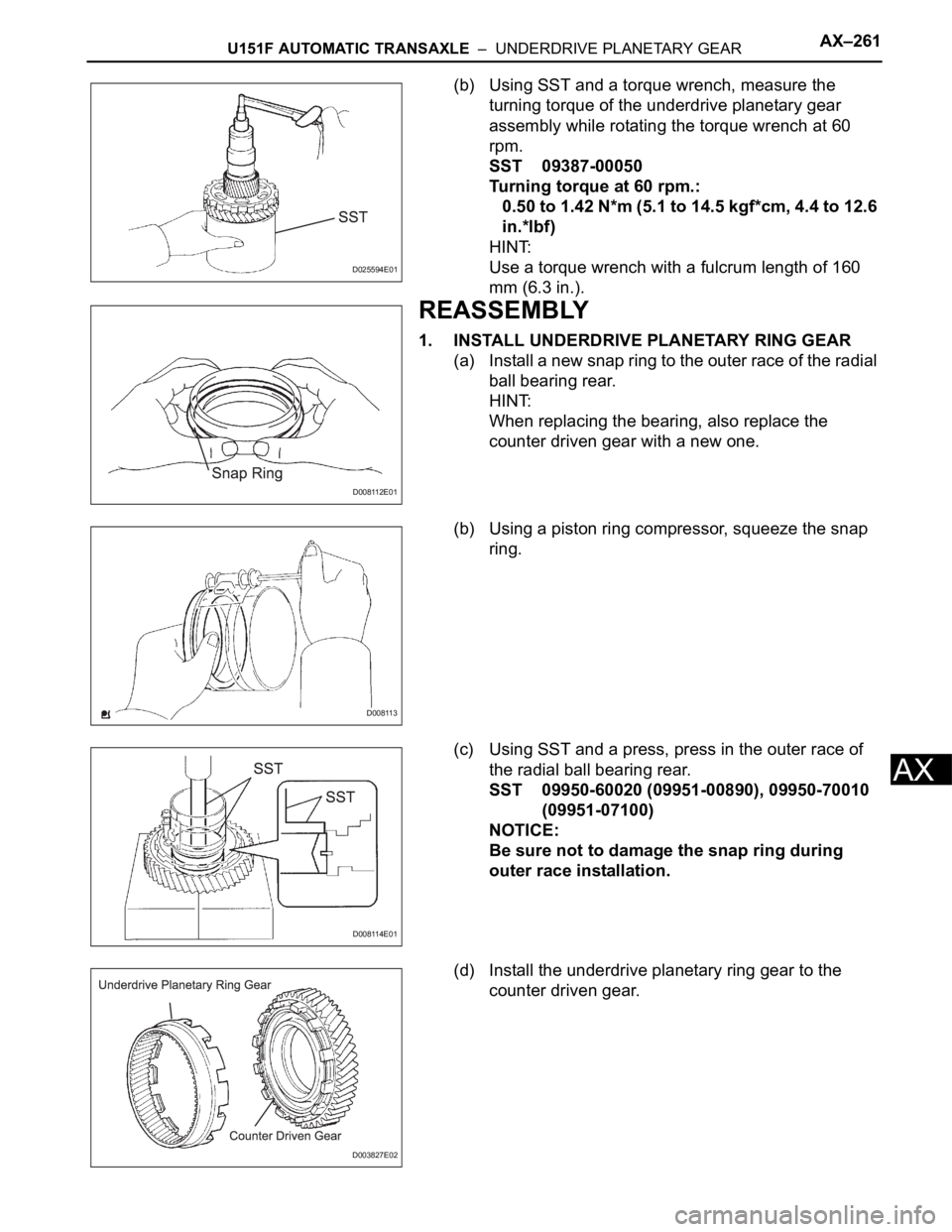
(b) Using SST and a torque wrench, measure the
turning torque of the underdrive planetary gear
assembly while rotating the torque wrench at 60
rpm.
SST 09387-00050
Turning torque at 60 rpm.:
0.50 to 1.42 N*m (5.1 to 14.5 kgf*cm, 4.4 to 12.6
in.*lbf)
HINT:
Use a torque wrench with a fulcrum length of 160
mm (6.3 in.).
REASSEMBLY
1. INSTALL UNDERDRIVE PLANETARY RING GEAR
(a) Install a new snap ring to the outer race of the radial
ball bearing rear.
HINT:
When replacing the bearing, also replace the
counter driven gear with a new one.
(b) Using a piston ring compressor, squeeze the snap
ring.
(c) Using SST and a press, press in the outer race of
the radial ball bearing rear.
SST 09950-60020 (09951-00890), 09950-70010
(09951-07100)
NOTICE:
Be sure not to damage the snap ring during
outer race installation.
(d) Install the underdrive planetary ring gear to the
counter driven gear.
D025594E01
D008112E01
D008113
D008114E01
D003827E02
Page 1985 of 3000
U151F AUTOMATIC TRANSAXLE – UNDERDRIVE PLANETARY GEARAX–263
AX
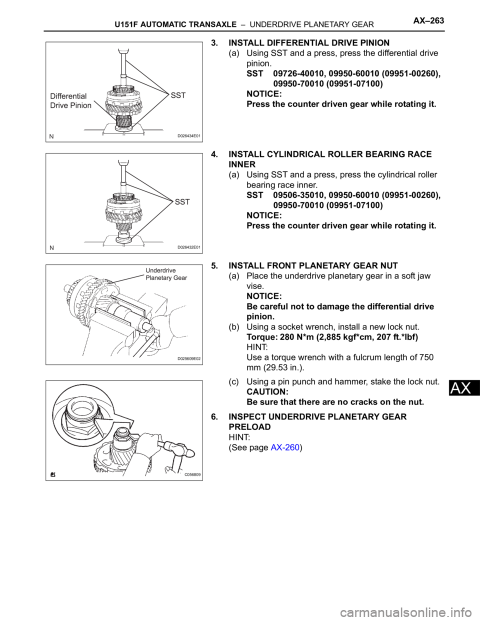
3. INSTALL DIFFERENTIAL DRIVE PINION
(a) Using SST and a press, press the differential drive
pinion.
SST 09726-40010, 09950-60010 (09951-00260),
09950-70010 (09951-07100)
NOTICE:
Press the counter driven gear while rotating it.
4. INSTALL CYLINDRICAL ROLLER BEARING RACE
INNER
(a) Using SST and a press, press the cylindrical roller
bearing race inner.
SST 09506-35010, 09950-60010 (09951-00260),
09950-70010 (09951-07100)
NOTICE:
Press the counter driven gear while rotating it.
5. INSTALL FRONT PLANETARY GEAR NUT
(a) Place the underdrive planetary gear in a soft jaw
vise.
NOTICE:
Be careful not to damage the differential drive
pinion.
(b) Using a socket wrench, install a new lock nut.
Torque: 280 N*m (2,885 kgf*cm, 207 ft.*lbf)
HINT:
Use a torque wrench with a fulcrum length of 750
mm (29.53 in.).
(c) Using a pin punch and hammer, stake the lock nut.
CAUTION:
Be sure that there are no cracks on the nut.
6. INSPECT UNDERDRIVE PLANETARY GEAR
PRELOAD
HINT:
(See page AX-260)
D026434E01
D026432E01
D025609E02
C056809
Page 1989 of 3000
U151F AUTOMATIC TRANSAXLE – UNDERDRIVE CLUTCHAX–267
AX
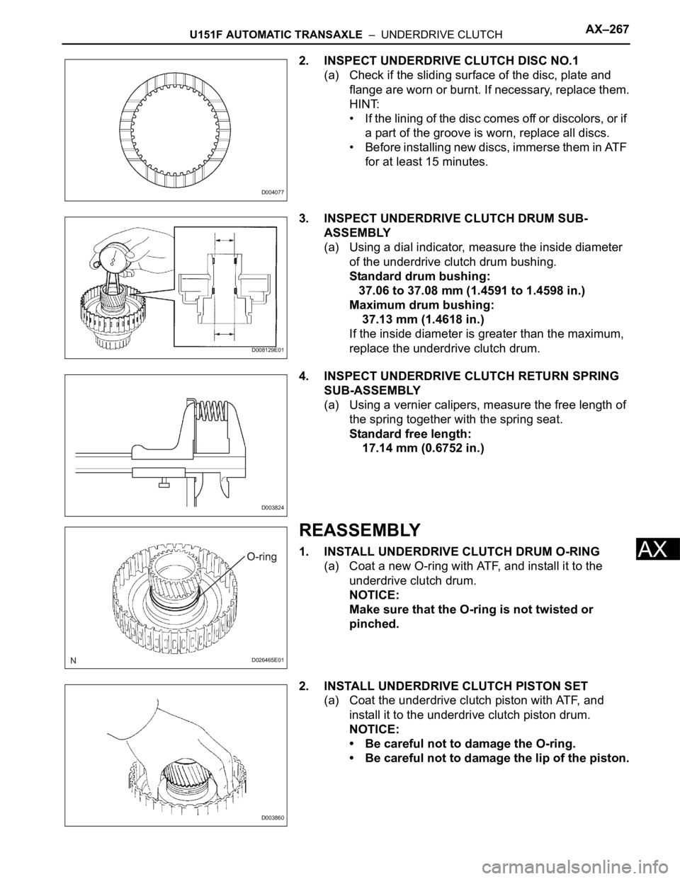
2. INSPECT UNDERDRIVE CLUTCH DISC NO.1
(a) Check if the sliding surface of the disc, plate and
flange are worn or burnt. If necessary, replace them.
HINT:
• If the lining of the disc comes off or discolors, or if
a part of the groove is worn, replace all discs.
• Before installing new discs, immerse them in ATF
for at least 15 minutes.
3. INSPECT UNDERDRIVE CLUTCH DRUM SUB-
ASSEMBLY
(a) Using a dial indicator, measure the inside diameter
of the underdrive clutch drum bushing.
Standard drum bushing:
37.06 to 37.08 mm (1.4591 to 1.4598 in.)
Maximum drum bushing:
37.13 mm (1.4618 in.)
If the inside diameter is greater than the maximum,
replace the underdrive clutch drum.
4. INSPECT UNDERDRIVE CLUTCH RETURN SPRING
SUB-ASSEMBLY
(a) Using a vernier calipers, measure the free length of
the spring together with the spring seat.
Standard free length:
17.14 mm (0.6752 in.)
REASSEMBLY
1. INSTALL UNDERDRIVE CLUTCH DRUM O-RING
(a) Coat a new O-ring with ATF, and install it to the
underdrive clutch drum.
NOTICE:
Make sure that the O-ring is not twisted or
pinched.
2. INSTALL UNDERDRIVE CLUTCH PISTON SET
(a) Coat the underdrive clutch piston with ATF, and
install it to the underdrive clutch piston drum.
NOTICE:
• Be careful not to damage the O-ring.
• Be careful not to damage the lip of the piston.
D004077
D008129E01
D003824
D026465E01
D003860
Page 1995 of 3000
U151F AUTOMATIC TRANSAXLE – DIFFERENTIAL CASEAX–279
AX
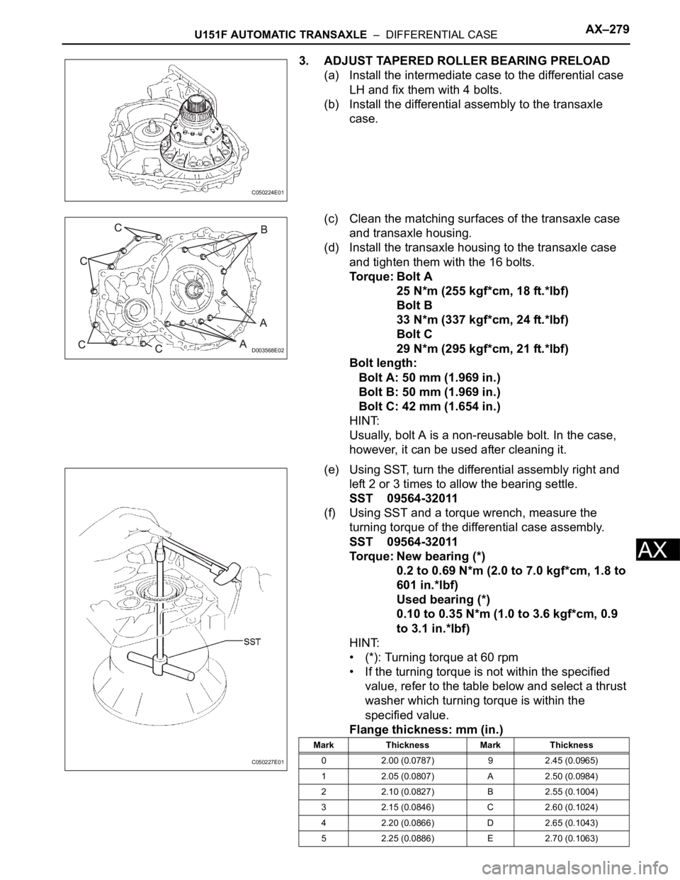
3. ADJUST TAPERED ROLLER BEARING PRELOAD
(a) Install the intermediate case to the differential case
LH and fix them with 4 bolts.
(b) Install the differential assembly to the transaxle
case.
(c) Clean the matching surfaces of the transaxle case
and transaxle housing.
(d) Install the transaxle housing to the transaxle case
and tighten them with the 16 bolts.
Torque: Bolt A
25 N*m (255 kgf*cm, 18 ft.*lbf)
Bolt B
33 N*m (337 kgf*cm, 24 ft.*lbf)
Bolt C
29 N*m (295 kgf*cm, 21 ft.*lbf)
Bolt length:
Bolt A: 50 mm (1.969 in.)
Bolt B: 50 mm (1.969 in.)
Bolt C: 42 mm (1.654 in.)
HINT:
Usually, bolt A is a non-reusable bolt. In the case,
however, it can be used after cleaning it.
(e) Using SST, turn the differential assembly right and
left 2 or 3 times to allow the bearing settle.
SST 09564-32011
(f) Using SST and a torque wrench, measure the
turning torque of the differential case assembly.
SST 09564-32011
Torque: New bearing (*)
0.2 to 0.69 N*m (2.0 to 7.0 kgf*cm, 1.8 to
601 in.*lbf)
Used bearing (*)
0.10 to 0.35 N*m (1.0 to 3.6 kgf*cm, 0.9
to 3.1 in.*lbf)
HINT:
• (*): Turning torque at 60 rpm
• If the turning torque is not within the specified
value, refer to the table below and select a thrust
washer which turning torque is within the
specified value.
Flange thickness: mm (in.)
C050224E01
D003568E02
C050227E01
Mark Thickness Mark Thickness
0 2.00 (0.0787) 9 2.45 (0.0965)
1 2.05 (0.0807) A 2.50 (0.0984)
2 2.10 (0.0827) B 2.55 (0.1004)
3 2.15 (0.0846) C 2.60 (0.1024)
4 2.20 (0.0866) D 2.65 (0.1043)
5 2.25 (0.0886) E 2.70 (0.1063)
Page 2005 of 3000
TRANSFER – TRANSFER UNITTF–15
TF
(b) Using a plastic hammer, remove the transfer
extension housing sub- assembly from the transfer
case.
12. INSPECT PRELOAD
(a) Using SST(s) and a torque wrench, check the initial
torque with the backlash range.
SST 09326-20011
Torque: 0.9 to 1.4 N*m (9 to 14 kgf*cm, 8.0 to
12.4 in.*lbf)
HINT:
Use a torque wrench with a fulcrum length of 160
mm (6.30 in.)
(b) Using SST(s) and a torque wrench, check the initial
torque while the driven pinion is in contact with the
ring gear face.
SST 09326-20011
Torque: Preload
+ 0.15 to 0.30 N*m (+ 1.6 to 3.1 kgf*cm, +
1.3 to 2.7 in.*lbf)
HINT:
Use a torque wrench with a fulcrum length of 160
mm (6.30 in.)
13. REMOVE CTR DIFFERENTIAL LOCK SLEEVE
(a) Using snap ring pliers, remove the shaft snap ring.
(b) Using SST(s), remove the CTR differential lock
sleeve.
SST 09308-00010
C082791
C083635E01
C083637
C083638E01
Page 2011 of 3000
TRANSFER – TRANSFER UNITTF–21
TF
INSPECTION
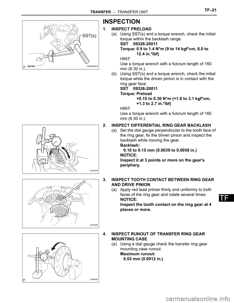
1. INSPECT PRELOAD
(a) Using SST(s) and a torque wrench, check the initial
torque within the backlash range.
SST 09326-20011
Torque: 0.9 to 1.4 N*m (9 to 14 kgf*cm, 8.0 to
12.4 in.*lbf)
HINT:
Use a torque wrench with a fulcrum length of 160
mm (6.30 in.).
(b) Using SST(s) and a torque wrench, check the initial
torque while the driven pinion is in contact with the
ring gear face.
SST 09326-20011
Torque: Preload
+0.15 to 0.30 N*m (+1.6 to 3.1 kgf*cm,
+1.3 to 2.7 in.*lbf)
HINT:
Use a torque wrench with a fulcrum length of 160
mm (6.30 in.).
2. INSPECT DIFFERENTIAL RING GEAR BACKLASH
(a) Set the dial gauge perpendicular to the tooth face of
the ring gear, fix the driven pinion and inspect the
backlash while moving the gear.
Backlash:
0.10 to 0.15 mm (0.0039 to 0.0059 in.)
NOTICE:
Inspect it at 3 points or more on the gear's
periphery.
3. INSPECT TOOTH CONTACT BETWEEN RING GEAR
AND DRIVE PINION
(a) Apply red lead primer thinly and uniformly to both
faces of the ring gear and rotate several times.
NOTICE:
Inspect the tooth contact on the ring gear at 4
places or more.
4. INSPECT RUNOUT OF TRANSFER RING GEAR
MOUNTING CASE
(a) Using a dial gauge check the transfer ring gear
mounting case runout.
Maximum runout:
0.03 mm (0.0012 in.)
C083635E05
C050309
C050346
C099000
Page 2013 of 3000
TRANSFER – TRANSFER UNITTF–23
TF
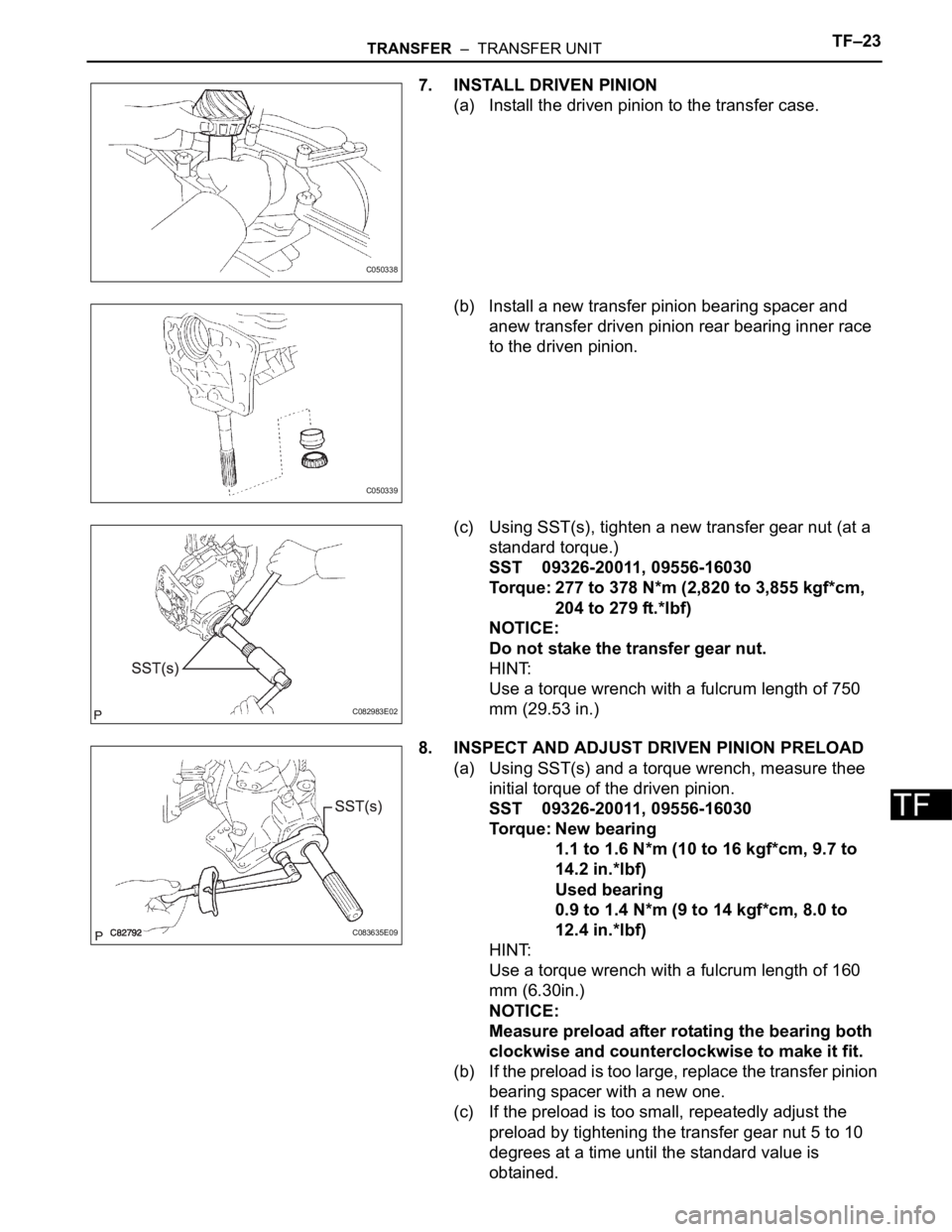
7. INSTALL DRIVEN PINION
(a) Install the driven pinion to the transfer case.
(b) Install a new transfer pinion bearing spacer and
anew transfer driven pinion rear bearing inner race
to the driven pinion.
(c) Using SST(s), tighten a new transfer gear nut (at a
standard torque.)
SST 09326-20011, 09556-16030
Torque: 277 to 378 N*m (2,820 to 3,855 kgf*cm,
204 to 279 ft.*lbf)
NOTICE:
Do not stake the transfer gear nut.
HINT:
Use a torque wrench with a fulcrum length of 750
mm (29.53 in.)
8. INSPECT AND ADJUST DRIVEN PINION PRELOAD
(a) Using SST(s) and a torque wrench, measure thee
initial torque of the driven pinion.
SST 09326-20011, 09556-16030
Torque: New bearing
1.1 to 1.6 N*m (10 to 16 kgf*cm, 9.7 to
14.2 in.*lbf)
Used bearing
0.9 to 1.4 N*m (9 to 14 kgf*cm, 8.0 to
12.4 in.*lbf)
HINT:
Use a torque wrench with a fulcrum length of 160
mm (6.30in.)
NOTICE:
Measure preload after rotating the bearing both
clockwise and counterclockwise to make it fit.
(b) If the preload is too large, replace the transfer pinion
bearing spacer with a new one.
(c) If the preload is too small, repeatedly adjust the
preload by tightening the transfer gear nut 5 to 10
degrees at a time until the standard value is
obtained.
C050338
C050339
C082983E02
C083635E09