Page 2019 of 3000
TRANSFER – TRANSFER UNITTF–29
TF
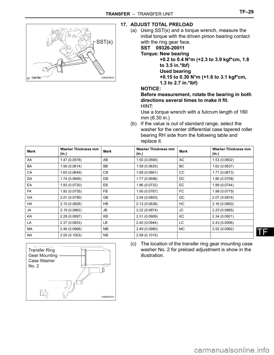
17. ADJUST TOTAL PRELOAD
(a) Using SST(s) and a torque wrench, measure the
initial torque with the driven pinion bearing contact
with the ring gear face.
SST 09326-20011
Torque: New bearing
+0.2 to 0.4 N*m (+2.3 to 3.9 kgf*cm, 1.8
to 3.5 in.*lbf)
Used bearing
+0.15 to 0.30 N*m (+1.6 to 3.1 kgf*cm,
1.3 to 2.7 in.*lbf)
NOTICE:
Before measurement, rotate the bearing in both
directions several times to make it fit.
HINT:
Use a torque wrench with a fulcrum length of 160
mm (6.30 in.)
(b) If the value is out of standard range, select the
washer for the center differential case tapered roller
bearing RH side from the following table and
replace it.
(c) The location of the transfer ring gear mounting case
washer No. 2 for preload adjustment is show in the
illustration.
C083635E07
MarkWasher Thickness mm
(in.)MarkWasher Thickness mm
(in.)MarkWasher Thickness mm
(in.)
AA 1.47 (0.0578) AB 1.50 (0.0590) AC 1.53 (0.0602)
BA 1.56 (0.0614) BB 1.59 (0.0625) BC 1.62 (0.0637)
CA 1.65 (0.0649) CB 1.68 (0.0661) CC 1.71 (0.0673)
DA 1.74 (0.0685) DB 1.77 (0.0696) DC 1.80 (0.0708)
EA 1.83 (0.0720) EB 1.86 (0.0732) EC 1.89 (0.0744)
FA 1.92 (0.0755) FB 1.95 (0.0767) FC 1.98 (0.0779)
GA 2.01 (0.0790) GB 2.04 (0.0803) GC 2.07 (0.0814)
HA 2.10 (0.0826) HB 2.13 (0.0838) HC 2.16 (0.0850)
JA 2.19 (0.0862) JB 2.22 (0.0874) JC 2.25 (0.0885)
KA 2.28 (0.0897) KB 2.31 (0.0909) KC 2.34 (0.0921)
LA 2.37 (0.0933) LB 2.40 (0.0944) LC 2.43 (0.0956)
MA 2.46 (0.0968) MB 2.49 (0.0980) MC 2.52 (0.0992)
NA 2.55 (0.1003) NB 2.58 (0.1015)
C083657E01
Page 2024 of 3000
TF–34TRANSFER – TRANSFER UNIT
TF
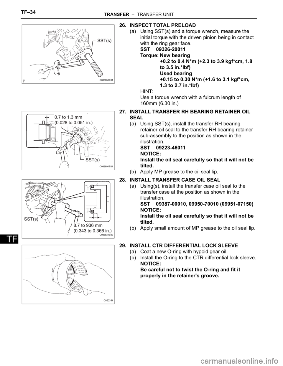
26. INSPECT TOTAL PRELOAD
(a) Using SST(s) and a torque wrench, measure the
initial torque with the driven pinion being in contact
with the ring gear face.
SST 09326-20011
Torque: New bearing
+0.2 to 0.4 N*m (+2.3 to 3.9 kgf*cm, 1.8
to 3.5 in.*lbf)
Used bearing
+0.15 to 0.30 N*m (+1.6 to 3.1 kgf*cm,
1.3 to 2.7 in.*lbf)
HINT:
Use a torque wrench with a fulcrum length of
160mm (6.30 in.)
27. INSTALL TRANSFER RH BEARING RETAINER OIL
SEAL
(a) Using SST(s), install the transfer RH bearing
retainer oil seal to the transfer RH bearing retainer
sub-assembly to the position as shown in the
illustration.
SST 09223-46011
NOTICE:
Install the oil seal carefully so that it will not be
tilted.
(b) Apply MP grease to the oil seal lip.
28. INSTALL TRANSFER CASE OIL SEAL
(a) Using(s), install the transfer case oil seal to the
transfer case at the position as shown in the
illustration.
SST 09387-00010, 09950-70010 (09951-07150)
NOTICE:
Install the oil seal carefully so that it will not be
tilted.
(b) Apply small amount of MP grease to the oil seal lip.
29. INSTALL CTR DIFFERENTIAL LOCK SLEEVE
(a) Coat a new O-ring with hypoid gear oil.
(b) Install the O-ring to the CTR differential lock sleeve.
NOTICE:
Be careful not to twist the O-ring and fit it
properly in the retainer's groove.
C083650E01
C083691E01
C083631E02
C050354
Page 2038 of 3000
TRANSFER – TRANSFER UNITTF–15
TF
(b) Using a plastic hammer, remove the transfer
extension housing sub- assembly from the transfer
case.
12. INSPECT PRELOAD
(a) Using SST(s) and a torque wrench, check the initial
torque with the backlash range.
SST 09326-20011
Torque: 0.9 to 1.4 N*m (9 to 14 kgf*cm, 8.0 to
12.4 in.*lbf)
HINT:
Use a torque wrench with a fulcrum length of 160
mm (6.30 in.)
(b) Using SST(s) and a torque wrench, check the initial
torque while the driven pinion is in contact with the
ring gear face.
SST 09326-20011
Torque: Preload
+ 0.15 to 0.30 N*m (+ 1.6 to 3.1 kgf*cm, +
1.3 to 2.7 in.*lbf)
HINT:
Use a torque wrench with a fulcrum length of 160
mm (6.30 in.)
13. REMOVE CTR DIFFERENTIAL LOCK SLEEVE
(a) Using snap ring pliers, remove the shaft snap ring.
(b) Using SST(s), remove the CTR differential lock
sleeve.
SST 09308-00010
C082791
C083635E01
C083637
C083638E01
Page 2044 of 3000
TRANSFER – TRANSFER UNITTF–21
TF
INSPECTION
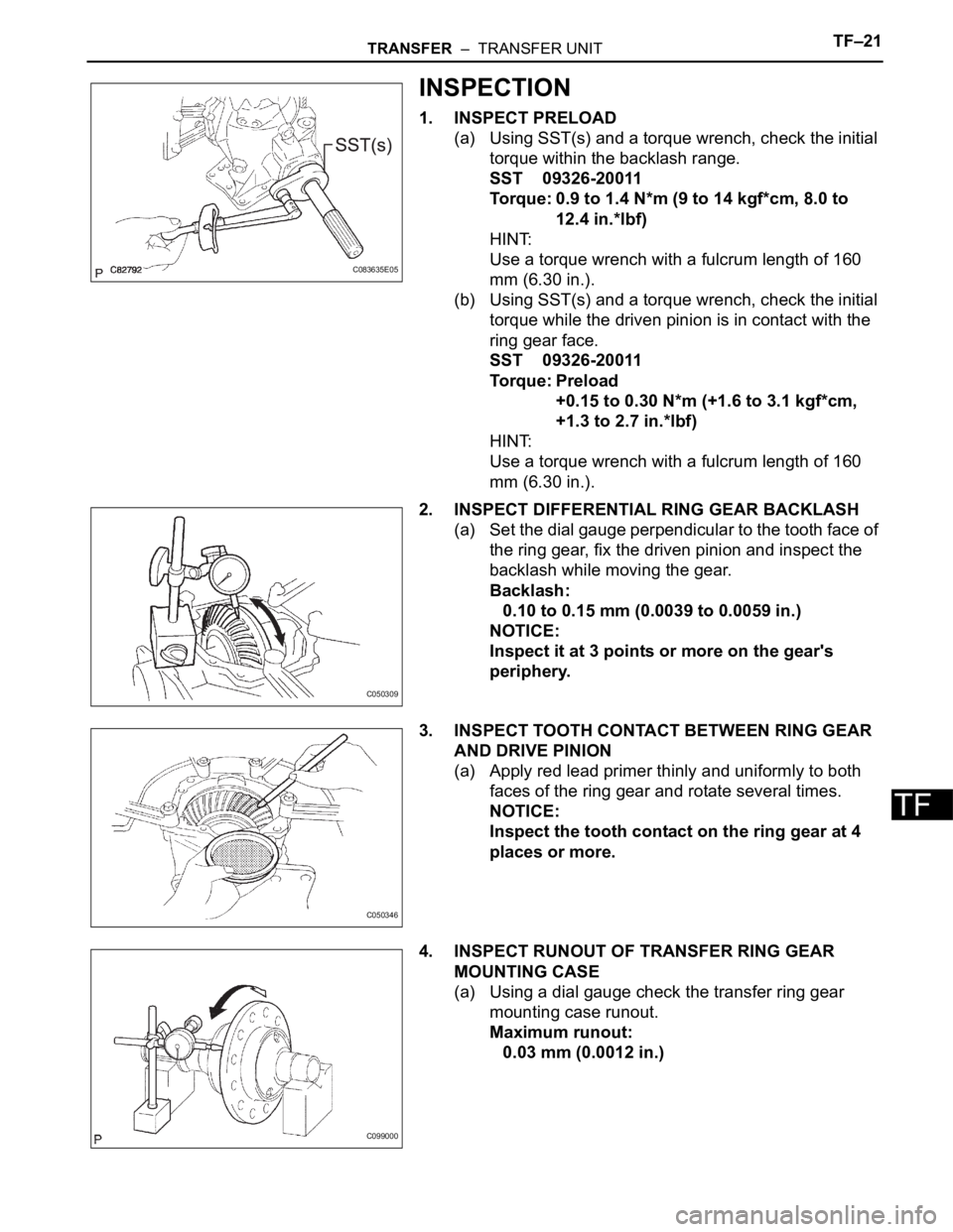
1. INSPECT PRELOAD
(a) Using SST(s) and a torque wrench, check the initial
torque within the backlash range.
SST 09326-20011
Torque: 0.9 to 1.4 N*m (9 to 14 kgf*cm, 8.0 to
12.4 in.*lbf)
HINT:
Use a torque wrench with a fulcrum length of 160
mm (6.30 in.).
(b) Using SST(s) and a torque wrench, check the initial
torque while the driven pinion is in contact with the
ring gear face.
SST 09326-20011
Torque: Preload
+0.15 to 0.30 N*m (+1.6 to 3.1 kgf*cm,
+1.3 to 2.7 in.*lbf)
HINT:
Use a torque wrench with a fulcrum length of 160
mm (6.30 in.).
2. INSPECT DIFFERENTIAL RING GEAR BACKLASH
(a) Set the dial gauge perpendicular to the tooth face of
the ring gear, fix the driven pinion and inspect the
backlash while moving the gear.
Backlash:
0.10 to 0.15 mm (0.0039 to 0.0059 in.)
NOTICE:
Inspect it at 3 points or more on the gear's
periphery.
3. INSPECT TOOTH CONTACT BETWEEN RING GEAR
AND DRIVE PINION
(a) Apply red lead primer thinly and uniformly to both
faces of the ring gear and rotate several times.
NOTICE:
Inspect the tooth contact on the ring gear at 4
places or more.
4. INSPECT RUNOUT OF TRANSFER RING GEAR
MOUNTING CASE
(a) Using a dial gauge check the transfer ring gear
mounting case runout.
Maximum runout:
0.03 mm (0.0012 in.)
C083635E05
C050309
C050346
C099000
Page 2046 of 3000
TRANSFER – TRANSFER UNITTF–23
TF
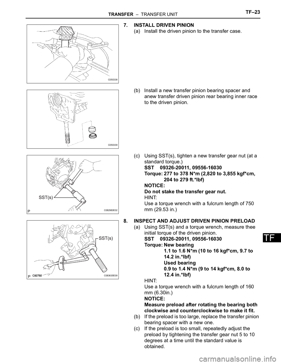
7. INSTALL DRIVEN PINION
(a) Install the driven pinion to the transfer case.
(b) Install a new transfer pinion bearing spacer and
anew transfer driven pinion rear bearing inner race
to the driven pinion.
(c) Using SST(s), tighten a new transfer gear nut (at a
standard torque.)
SST 09326-20011, 09556-16030
Torque: 277 to 378 N*m (2,820 to 3,855 kgf*cm,
204 to 279 ft.*lbf)
NOTICE:
Do not stake the transfer gear nut.
HINT:
Use a torque wrench with a fulcrum length of 750
mm (29.53 in.)
8. INSPECT AND ADJUST DRIVEN PINION PRELOAD
(a) Using SST(s) and a torque wrench, measure thee
initial torque of the driven pinion.
SST 09326-20011, 09556-16030
Torque: New bearing
1.1 to 1.6 N*m (10 to 16 kgf*cm, 9.7 to
14.2 in.*lbf)
Used bearing
0.9 to 1.4 N*m (9 to 14 kgf*cm, 8.0 to
12.4 in.*lbf)
HINT:
Use a torque wrench with a fulcrum length of 160
mm (6.30in.)
NOTICE:
Measure preload after rotating the bearing both
clockwise and counterclockwise to make it fit.
(b) If the preload is too large, replace the transfer pinion
bearing spacer with a new one.
(c) If the preload is too small, repeatedly adjust the
preload by tightening the transfer gear nut 5 to 10
degrees at a time until the standard value is
obtained.
C050338
C050339
C082983E02
C083635E09
Page 2052 of 3000
TRANSFER – TRANSFER UNITTF–29
TF
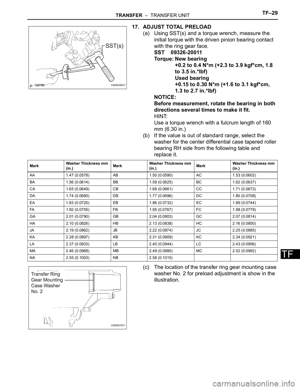
17. ADJUST TOTAL PRELOAD
(a) Using SST(s) and a torque wrench, measure the
initial torque with the driven pinion bearing contact
with the ring gear face.
SST 09326-20011
Torque: New bearing
+0.2 to 0.4 N*m (+2.3 to 3.9 kgf*cm, 1.8
to 3.5 in.*lbf)
Used bearing
+0.15 to 0.30 N*m (+1.6 to 3.1 kgf*cm,
1.3 to 2.7 in.*lbf)
NOTICE:
Before measurement, rotate the bearing in both
directions several times to make it fit.
HINT:
Use a torque wrench with a fulcrum length of 160
mm (6.30 in.)
(b) If the value is out of standard range, select the
washer for the center differential case tapered roller
bearing RH side from the following table and
replace it.
(c) The location of the transfer ring gear mounting case
washer No. 2 for preload adjustment is show in the
illustration.
C083635E07
MarkWasher Thickness mm
(in.)MarkWasher Thickness mm
(in.)MarkWasher Thickness mm
(in.)
AA 1.47 (0.0578) AB 1.50 (0.0590) AC 1.53 (0.0602)
BA 1.56 (0.0614) BB 1.59 (0.0625) BC 1.62 (0.0637)
CA 1.65 (0.0649) CB 1.68 (0.0661) CC 1.71 (0.0673)
DA 1.74 (0.0685) DB 1.77 (0.0696) DC 1.80 (0.0708)
EA 1.83 (0.0720) EB 1.86 (0.0732) EC 1.89 (0.0744)
FA 1.92 (0.0755) FB 1.95 (0.0767) FC 1.98 (0.0779)
GA 2.01 (0.0790) GB 2.04 (0.0803) GC 2.07 (0.0814)
HA 2.10 (0.0826) HB 2.13 (0.0838) HC 2.16 (0.0850)
JA 2.19 (0.0862) JB 2.22 (0.0874) JC 2.25 (0.0885)
KA 2.28 (0.0897) KB 2.31 (0.0909) KC 2.34 (0.0921)
LA 2.37 (0.0933) LB 2.40 (0.0944) LC 2.43 (0.0956)
MA 2.46 (0.0968) MB 2.49 (0.0980) MC 2.52 (0.0992)
NA 2.55 (0.1003) NB 2.58 (0.1015)
C083657E01
Page 2057 of 3000
TF–34TRANSFER – TRANSFER UNIT
TF
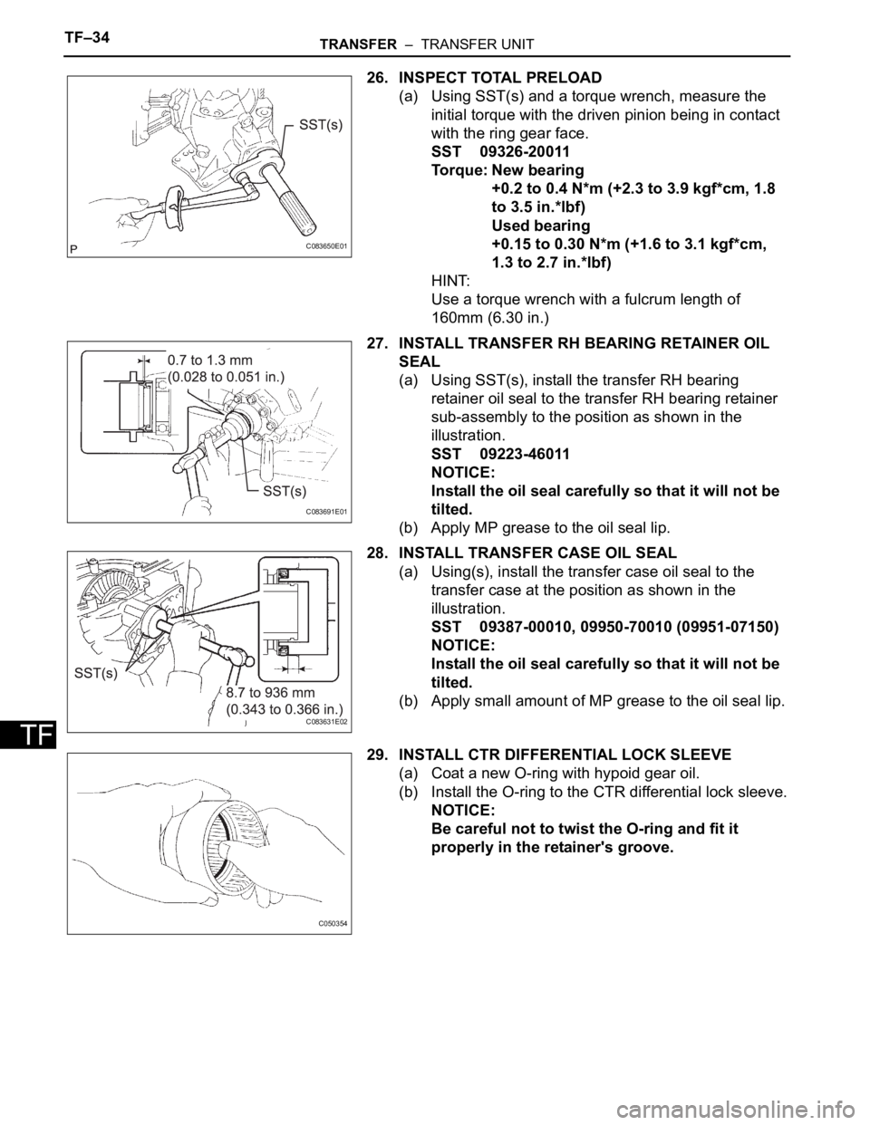
26. INSPECT TOTAL PRELOAD
(a) Using SST(s) and a torque wrench, measure the
initial torque with the driven pinion being in contact
with the ring gear face.
SST 09326-20011
Torque: New bearing
+0.2 to 0.4 N*m (+2.3 to 3.9 kgf*cm, 1.8
to 3.5 in.*lbf)
Used bearing
+0.15 to 0.30 N*m (+1.6 to 3.1 kgf*cm,
1.3 to 2.7 in.*lbf)
HINT:
Use a torque wrench with a fulcrum length of
160mm (6.30 in.)
27. INSTALL TRANSFER RH BEARING RETAINER OIL
SEAL
(a) Using SST(s), install the transfer RH bearing
retainer oil seal to the transfer RH bearing retainer
sub-assembly to the position as shown in the
illustration.
SST 09223-46011
NOTICE:
Install the oil seal carefully so that it will not be
tilted.
(b) Apply MP grease to the oil seal lip.
28. INSTALL TRANSFER CASE OIL SEAL
(a) Using(s), install the transfer case oil seal to the
transfer case at the position as shown in the
illustration.
SST 09387-00010, 09950-70010 (09951-07150)
NOTICE:
Install the oil seal carefully so that it will not be
tilted.
(b) Apply small amount of MP grease to the oil seal lip.
29. INSTALL CTR DIFFERENTIAL LOCK SLEEVE
(a) Coat a new O-ring with hypoid gear oil.
(b) Install the O-ring to the CTR differential lock sleeve.
NOTICE:
Be careful not to twist the O-ring and fit it
properly in the retainer's groove.
C083650E01
C083691E01
C083631E02
C050354
Page 2077 of 3000
DS–24DRIVE SHAFT – REAR DRIVE SHAFT (for 4WD)
DS
4. REMOVE REAR DRIVE SHAFT OUTBOARD JOINT
BOOT CLAMP
(a) Using pliers, remove the 2 rear drive shaft outboard
joint boot clamps as shown in the illustration.
5. REMOVE REAR DRIVE SHAFT OUTBOARD JOINT
BOOT
(a) Remove the outboard joint boot from the outboard
joint shaft.
(b) Remove the old grease from the outboard joint.
NOTICE:
Do not disassemble the outboard joint.
INSPECTION
1. INSPECT REAR DRIVE SHAFT ASSEMBLY LH
(a) Check that there is no remarkable play in the radial
direction of the outboard joint.
(b) Check that the inboard joint slides smoothly in the
thrust direction.
(c) Check that there is no remarkable play in the radial
direction of the inboard joint.
(d) Check the boots for damage.
(e) Make sure that the 2 boots are not stretched or
contracted when the drive shaft is at standard
length.
Standard length:
704.8 +- 5.0 mm (27.748 +- 0.20 in.)
G020982
Z012871
Z013445E01