Page 1578 of 3000
U151E AUTOMATIC TRANSAXLE – AUTOMATIC TRANSAXLE UNITAX–199
AX
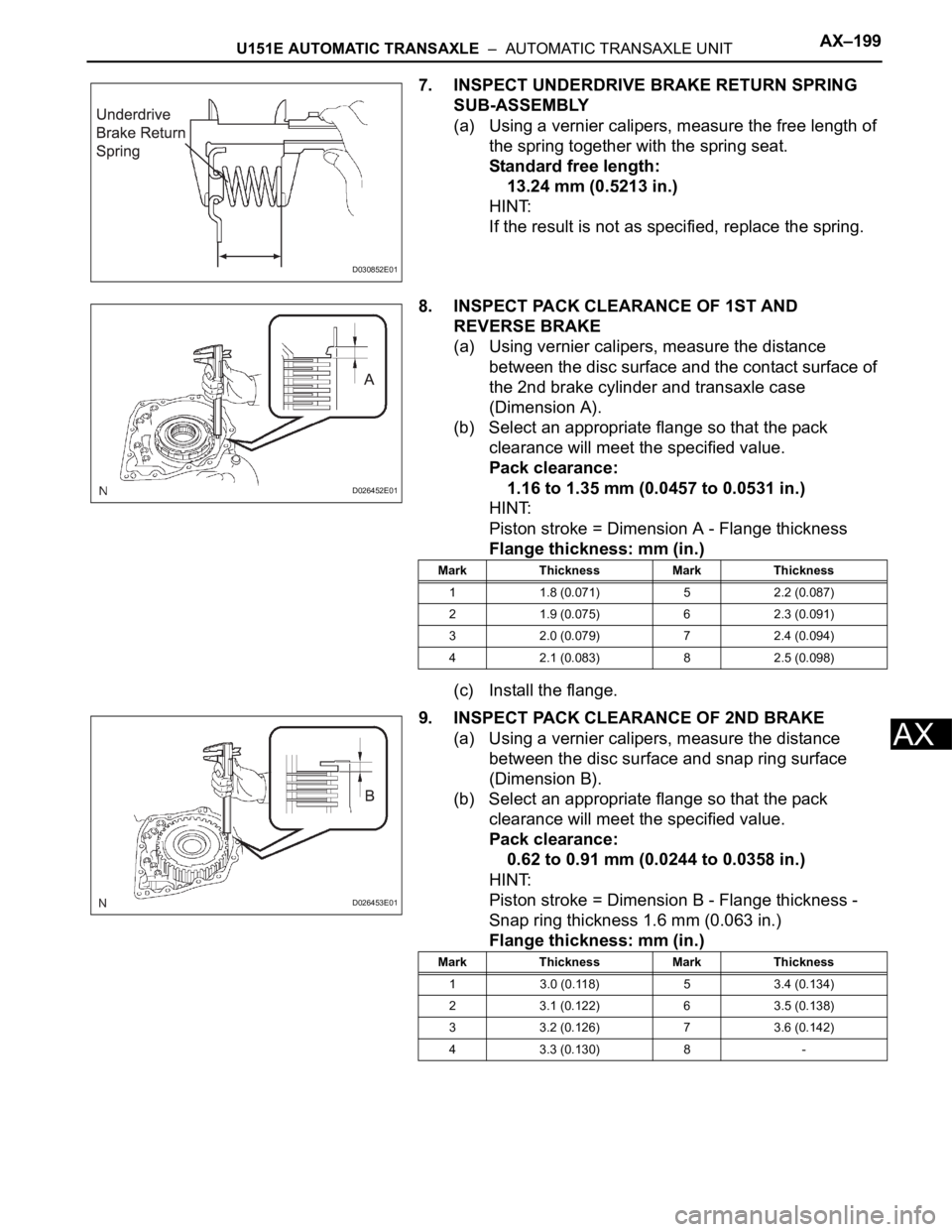
7. INSPECT UNDERDRIVE BRAKE RETURN SPRING
SUB-ASSEMBLY
(a) Using a vernier calipers, measure the free length of
the spring together with the spring seat.
Standard free length:
13.24 mm (0.5213 in.)
HINT:
If the result is not as specified, replace the spring.
8. INSPECT PACK CLEARANCE OF 1ST AND
REVERSE BRAKE
(a) Using vernier calipers, measure the distance
between the disc surface and the contact surface of
the 2nd brake cylinder and transaxle case
(Dimension A).
(b) Select an appropriate flange so that the pack
clearance will meet the specified value.
Pack clearance:
1.16 to 1.35 mm (0.0457 to 0.0531 in.)
HINT:
Piston stroke = Dimension A - Flange thickness
Flange thickness: mm (in.)
(c) Install the flange.
9. INSPECT PACK CLEARANCE OF 2ND BRAKE
(a) Using a vernier calipers, measure the distance
between the disc surface and snap ring surface
(Dimension B).
(b) Select an appropriate flange so that the pack
clearance will meet the specified value.
Pack clearance:
0.62 to 0.91 mm (0.0244 to 0.0358 in.)
HINT:
Piston stroke = Dimension B - Flange thickness -
Snap ring thickness 1.6 mm (0.063 in.)
Flange thickness: mm (in.)
D030852E01
D026452E01
Mark Thickness Mark Thickness
1 1.8 (0.071) 5 2.2 (0.087)
2 1.9 (0.075) 6 2.3 (0.091)
3 2.0 (0.079) 7 2.4 (0.094)
4 2.1 (0.083) 8 2.5 (0.098)
D026453E01
Mark Thickness Mark Thickness
1 3.0 (0.118) 5 3.4 (0.134)
2 3.1 (0.122) 6 3.5 (0.138)
3 3.2 (0.126) 7 3.6 (0.142)
4 3.3 (0.130) 8 -
Page 1594 of 3000
AX–208U151E AUTOMATIC TRANSAXLE – AUTOMATIC TRANSAXLE UNIT
AX
0.51 to 1.02 N*m (5.1 to 10.0 kgf*cm, 4.4 to 8.7
in.*lbf)
Used Bearing:
0.26 to 0.51 N*m (2.7 to 5.2 kgf*cm, 2.3 to 4.5
in.*lbf)
HINT:
Use a torque wrench with a fulcrum length of 160
mm (6.3 in.).
(f) Tighten the nut gradually until the specified turning
torque of tapered roller bearing is measured.
Torque: 350 N*m (3,569 kgf*cm, 258 ft.*lbf)
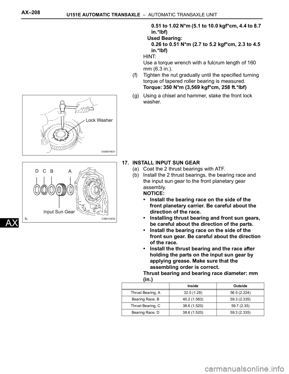
(g) Using a chisel and hammer, stake the front lock
washer.
17. INSTALL INPUT SUN GEAR
(a) Coat the 2 thrust bearings with ATF.
(b) Install the 2 thrust bearings, the bearing race and
the input sun gear to the front planetary gear
assembly.
NOTICE:
• Install the bearing race on the side of the
front planetary carrier. Be careful about the
direction of the race.
• Installing thrust bearing and front sun gears,
be careful about the direction of the parts.
• Install the bearing race on the side of the
front sun gear. Be careful about the direction
of the race.
• Install the thrust bearing and the race after
holding the parts on the input sun gear by
applying grease. Make sure that the
assembling order is correct.
Thrust bearing and bearing race diameter: mm
(in.)
D008074E01
C089123E02
Inside Outside
Thrust Bearing, A 32.5 (1.28) 56.5 (2.224)
Bearing Race, B 40.2 (1.583) 59.3 (2.335)
Thrust Bearing, C 38.6 (1.520) 59.7 (2.35)
Bearing Race, D 38.6 (1.520) 59.3 (2.335)
Page 1608 of 3000
AX–222U151E AUTOMATIC TRANSAXLE – AUTOMATIC TRANSAXLE UNIT
AX
(b) Coat the O-ring of oil pump with ATF.
NOTICE:
Confirm that the input shaft rotates smoothly
with the manual operation after installing the oil
pump.
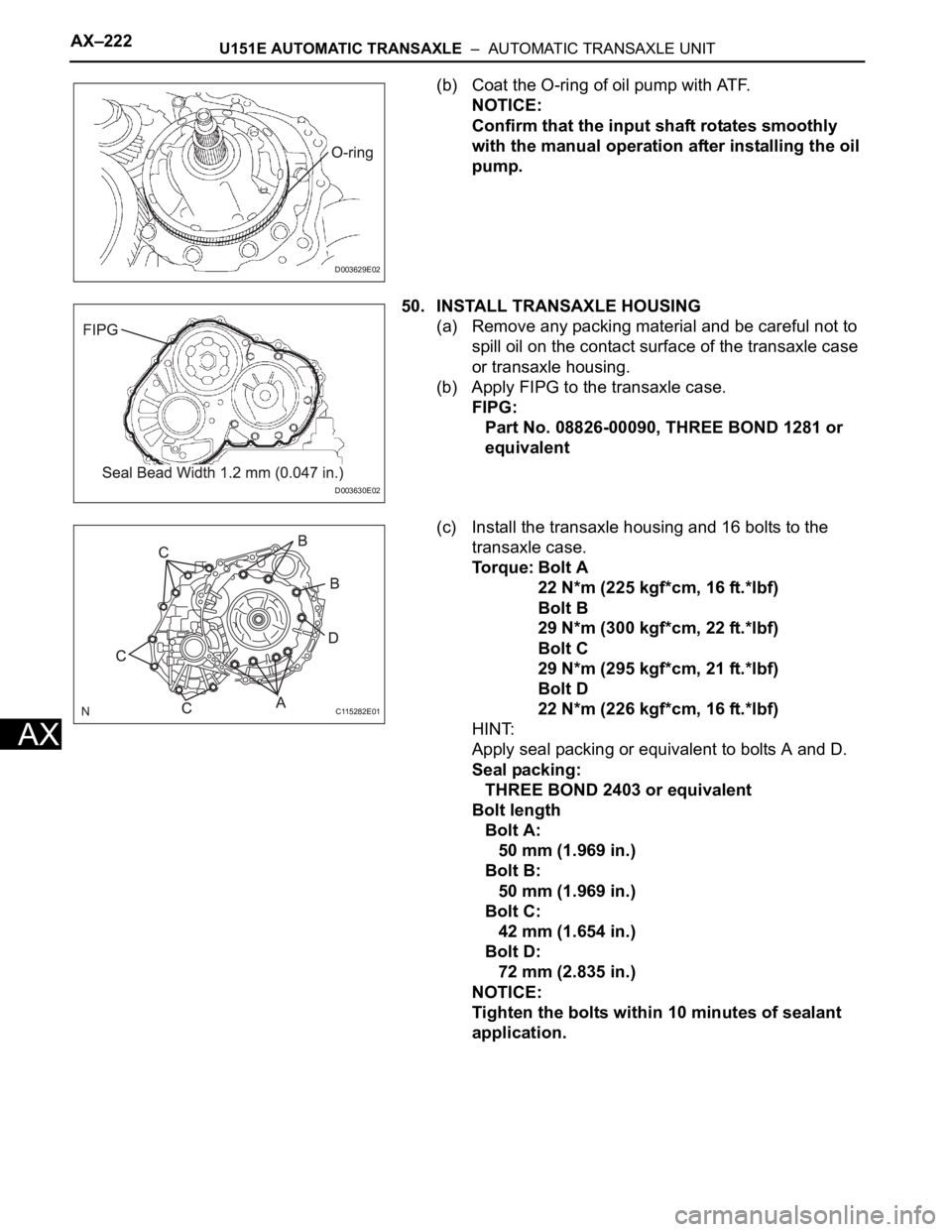
50. INSTALL TRANSAXLE HOUSING
(a) Remove any packing material and be careful not to
spill oil on the contact surface of the transaxle case
or transaxle housing.
(b) Apply FIPG to the transaxle case.
FIPG:
Part No. 08826-00090, THREE BOND 1281 or
equivalent
(c) Install the transaxle housing and 16 bolts to the
transaxle case.
To r q u e : B o l t A
22 N*m (225 kgf*cm, 16 ft.*lbf)
Bolt B
29 N*m (300 kgf*cm, 22 ft.*lbf)
Bolt C
29 N*m (295 kgf*cm, 21 ft.*lbf)
Bolt D
22 N*m (226 kgf*cm, 16 ft.*lbf)
HINT:
Apply seal packing or equivalent to bolts A and D.
Seal packing:
THREE BOND 2403 or equivalent
Bolt length
Bolt A:
50 mm (1.969 in.)
Bolt B:
50 mm (1.969 in.)
Bolt C:
42 mm (1.654 in.)
Bolt D:
72 mm (2.835 in.)
NOTICE:
Tighten the bolts within 10 minutes of sealant
application.
D003629E02
D003630E02
C115282E01
Page 1610 of 3000
AX–224U151E AUTOMATIC TRANSAXLE – AUTOMATIC TRANSAXLE UNIT
AX
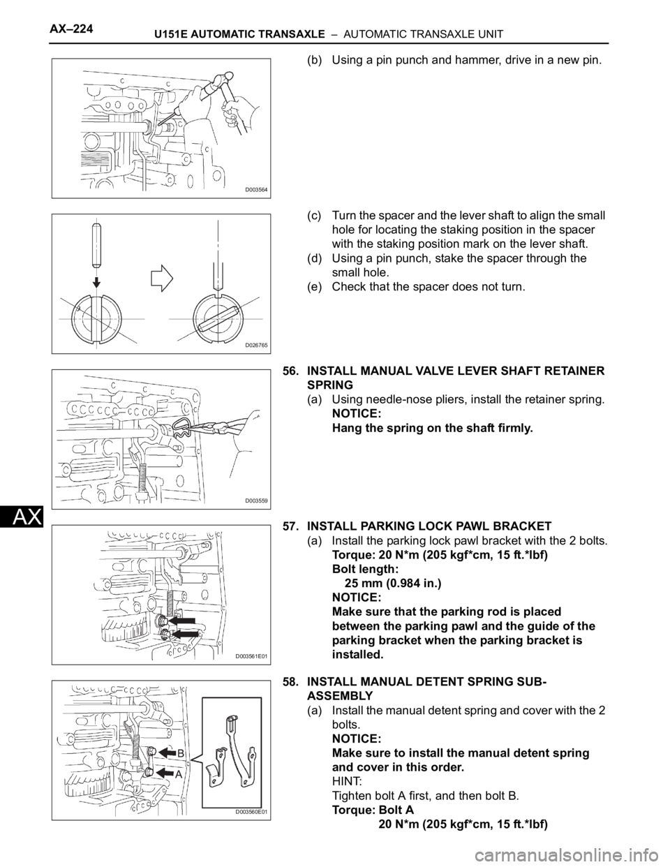
(b) Using a pin punch and hammer, drive in a new pin.
(c) Turn the spacer and the lever shaft to align the small
hole for locating the staking position in the spacer
with the staking position mark on the lever shaft.
(d) Using a pin punch, stake the spacer through the
small hole.
(e) Check that the spacer does not turn.
56. INSTALL MANUAL VALVE LEVER SHAFT RETAINER
SPRING
(a) Using needle-nose pliers, install the retainer spring.
NOTICE:
Hang the spring on the shaft firmly.
57. INSTALL PARKING LOCK PAWL BRACKET
(a) Install the parking lock pawl bracket with the 2 bolts.
Torque: 20 N*m (205 kgf*cm, 15 ft.*lbf)
Bolt length:
25 mm (0.984 in.)
NOTICE:
Make sure that the parking rod is placed
between the parking pawl and the guide of the
parking bracket when the parking bracket is
installed.
58. INSTALL MANUAL DETENT SPRING SUB-
ASSEMBLY
(a) Install the manual detent spring and cover with the 2
bolts.
NOTICE:
Make sure to install the manual detent spring
and cover in this order.
HINT:
Tighten bolt A first, and then bolt B.
To r q u e : B o l t A
20 N*m (205 kgf*cm, 15 ft.*lbf)
D003564
D026765
D003559
D003561E01
D003560E01
Page 1611 of 3000
U151E AUTOMATIC TRANSAXLE – AUTOMATIC TRANSAXLE UNITAX–225
AX
Bolt B
12 N*m (120 kgf*cm, 9 ft.*lbf)
Bolt length:
Bolt A:
27 mm (1.063 in.)
Bolt B:
16 mm (0.630 in.)
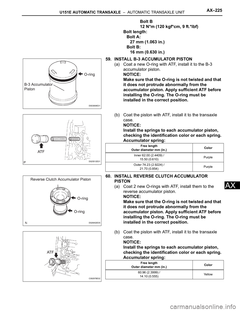
59. INSTALL B-3 ACCUMULATOR PISTON
(a) Coat a new O-ring with ATF, install it to the B-3
accumulator piston.
NOTICE:
Make sure that the O-ring is not twisted and that
it does not protrude abnormally from the
accumulator piston. Apply sufficient ATF before
installing the O-ring. The O-ring must be
installed in the correct position.
(b) Coat the piston with ATF, install it to the transaxle
case.
NOTICE:
Install the springs to each accumulator piston,
checking the identification color or each spring.
Accumulator spring:
60. INSTALL REVERSE CLUTCH ACCUMULATOR
PISTON
(a) Coat 2 new O-rings with ATF, install them to the
reverse accumulator piston.
NOTICE:
Make sure that the O-ring is not twisted and that
it does not protrude abnormally from the
accumulator piston. Apply sufficient ATF before
installing the O-ring. The O-ring must be
installed in the correct position.
(b) Coat the piston with ATF, install it to the transaxle
case.
NOTICE:
Install the springs to each accumulator piston,
checking the identification color or each spring.
Accumulator spring:
D003904E01
D025512E01
Free length
Outer diameter mm (in.)Color
Inner 62.00 (2.4409) /
15.50 (0.610)Purple
Outer 74.23 (2.9224) /
21.70 (0.854)Purple
D026402E05
C092978E02
Free length
Outer diameter mm (in.)Color
60.96 (2.3999) /
14.10 (0.555)Ye l l o w
Page 1612 of 3000
AX–226U151E AUTOMATIC TRANSAXLE – AUTOMATIC TRANSAXLE UNIT
AX
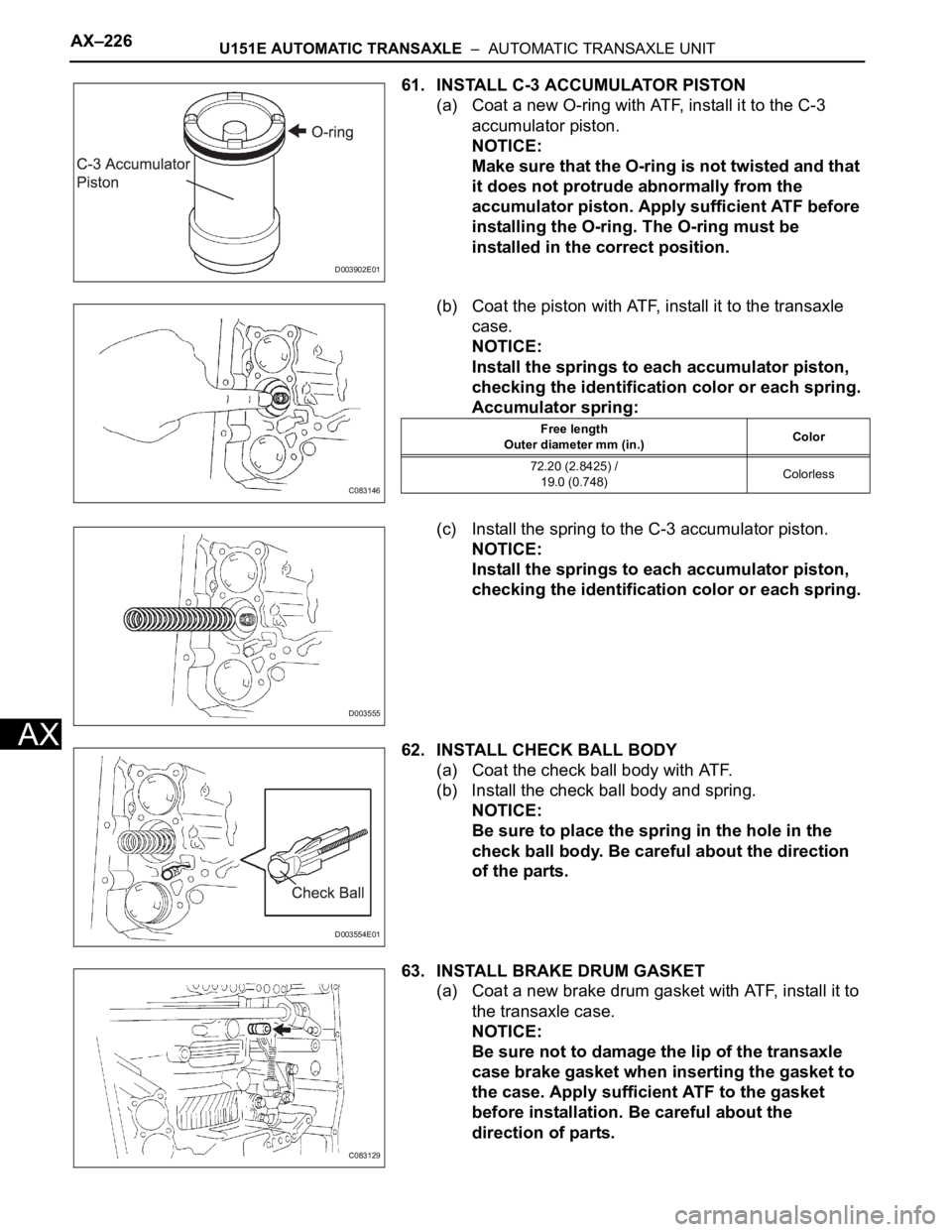
61. INSTALL C-3 ACCUMULATOR PISTON
(a) Coat a new O-ring with ATF, install it to the C-3
accumulator piston.
NOTICE:
Make sure that the O-ring is not twisted and that
it does not protrude abnormally from the
accumulator piston. Apply sufficient ATF before
installing the O-ring. The O-ring must be
installed in the correct position.
(b) Coat the piston with ATF, install it to the transaxle
case.
NOTICE:
Install the springs to each accumulator piston,
checking the identification color or each spring.
Accumulator spring:
(c) Install the spring to the C-3 accumulator piston.
NOTICE:
Install the springs to each accumulator piston,
checking the identification color or each spring.
62. INSTALL CHECK BALL BODY
(a) Coat the check ball body with ATF.
(b) Install the check ball body and spring.
NOTICE:
Be sure to place the spring in the hole in the
check ball body. Be careful about the direction
of the parts.
63. INSTALL BRAKE DRUM GASKET
(a) Coat a new brake drum gasket with ATF, install it to
the transaxle case.
NOTICE:
Be sure not to damage the lip of the transaxle
case brake gasket when inserting the gasket to
the case. Apply sufficient ATF to the gasket
before installation. Be careful about the
direction of parts.
D003902E01
C083146
Free length
Outer diameter mm (in.)Color
72.20 (2.8425) /
19.0 (0.748)Colorless
D003555
D003554E01
C083129
Page 1614 of 3000
AX–228U151E AUTOMATIC TRANSAXLE – AUTOMATIC TRANSAXLE UNIT
AX
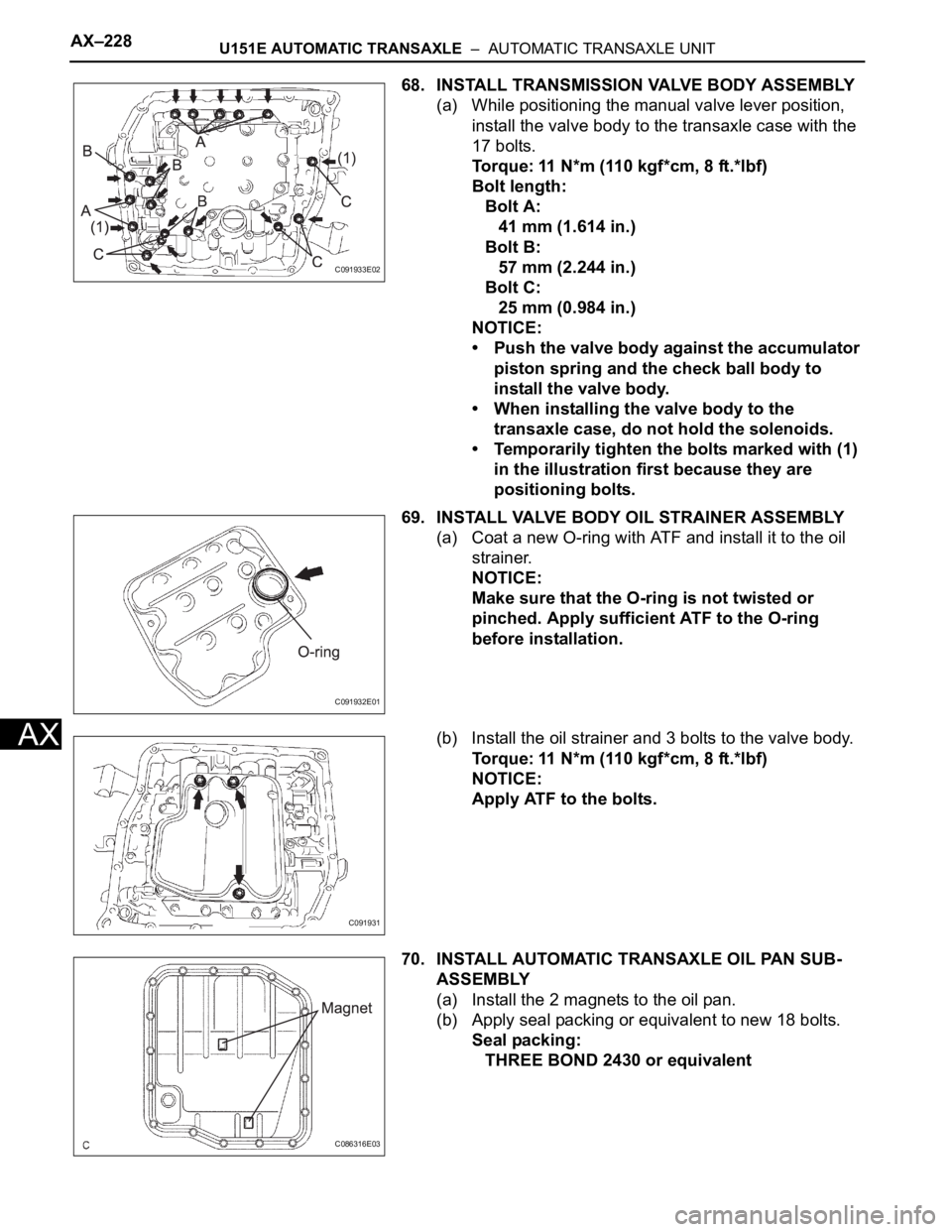
68. INSTALL TRANSMISSION VALVE BODY ASSEMBLY
(a) While positioning the manual valve lever position,
install the valve body to the transaxle case with the
17 bolts.
Torque: 11 N*m (110 kgf*cm, 8 ft.*lbf)
Bolt length:
Bolt A:
41 mm (1.614 in.)
Bolt B:
57 mm (2.244 in.)
Bolt C:
25 mm (0.984 in.)
NOTICE:
• Push the valve body against the accumulator
piston spring and the check ball body to
install the valve body.
• When installing the valve body to the
transaxle case, do not hold the solenoids.
• Temporarily tighten the bolts marked with (1)
in the illustration first because they are
positioning bolts.
69. INSTALL VALVE BODY OIL STRAINER ASSEMBLY
(a) Coat a new O-ring with ATF and install it to the oil
strainer.
NOTICE:
Make sure that the O-ring is not twisted or
pinched. Apply sufficient ATF to the O-ring
before installation.
(b) Install the oil strainer and 3 bolts to the valve body.
Torque: 11 N*m (110 kgf*cm, 8 ft.*lbf)
NOTICE:
Apply ATF to the bolts.
70. INSTALL AUTOMATIC TRANSAXLE OIL PAN SUB-
ASSEMBLY
(a) Install the 2 magnets to the oil pan.
(b) Apply seal packing or equivalent to new 18 bolts.
Seal packing:
THREE BOND 2430 or equivalent
C091933E02
C091932E01
C091931
C086316E03
Page 1619 of 3000
U151E AUTOMATIC TRANSAXLE – TORQUE CONVERTER CLUTCH AND DRIVE PLATEAX–171
AX
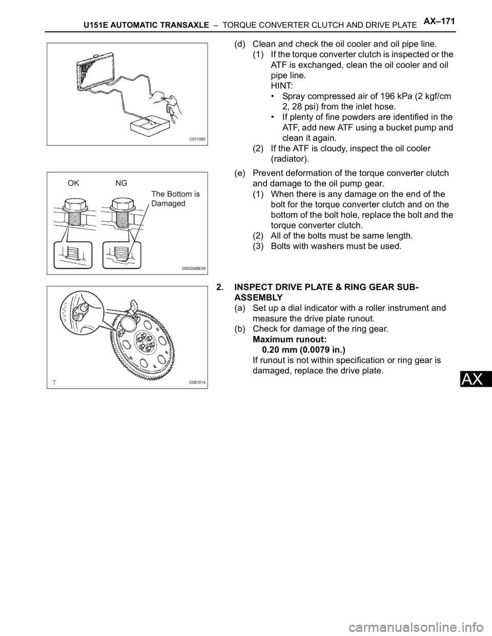
(d) Clean and check the oil cooler and oil pipe line.
(1) If the torque converter clutch is inspected or the
ATF is exchanged, clean the oil cooler and oil
pipe line.
HINT:
• Spray compressed air of 196 kPa (2 kgf/cm
2, 28 psi) from the inlet hose.
• If plenty of fine powders are identified in the
ATF, add new ATF using a bucket pump and
clean it again.
(2) If the ATF is cloudy, inspect the oil cooler
(radiator).
(e) Prevent deformation of the torque converter clutch
and damage to the oil pump gear.
(1) When there is any damage on the end of the
bolt for the torque converter clutch and on the
bottom of the bolt hole, replace the bolt and the
torque converter clutch.
(2) All of the bolts must be same length.
(3) Bolts with washers must be used.
2. INSPECT DRIVE PLATE & RING GEAR SUB-
ASSEMBLY
(a) Set up a dial indicator with a roller instrument and
measure the drive plate runout.
(b) Check for damage of the ring gear.
Maximum runout:
0.20 mm (0.0079 in.)
If runout is not within specification or ring gear is
damaged, replace the drive plate.
C011090
D025368E08
C081014