Page 1005 of 3000
EM–462GR-FE ENGINE MECHANICAL – ENGINE ASSEMBLY
EM
8. INSTALL NO. 2 IDLER PULLEY SUB-ASSEMBLY
(a) Install the No. 2 idler pulley sub-assembly and cover
plate with the bolt.
Torque: 43 N*m (438 kgf*cm, 32 ft.*lbf)
9. INSTALL NO. 2 TIMING GEAR COVER
(a) Install the No. 2 timing gear cover with the 2 bolts.
Torque: 6.0 N*m (61 kgf*cm, 53 in.*lbf)
10. INSTALL V-RIBBED BELT TENSIONER ASSEMBLY
(a) Temporarily install the V-ribbed belt tensioner with
the 5 bolts.
HINT:
Each bolt length is as follows:
A: 70 mm (2.76 in.)
B: 33 mm (1.30 in.)
(b) Install the V-ribbed belt tensioner by tightening the
bolt 1 and bolt 2 in the order shown in the
illustration.
Torque: 43 N*m (438 kgf*cm, 32 ft.*lbf)
(c) Tighten the other bolts.
Torque: 43 N*m (438 kgf*cm, 32 ft.*lbf)
11. INSTALL GENERATOR ASSEMBLY (See page CH-26)
12. INSTALL COOLER COMPRESSOR ASSEMBLY (See
page AC-231)
A129645E01
A132987
A129644E01
Page 1054 of 3000
2GR-FE ENGINE MECHANICAL – ENGINE UNITEM–107
EM
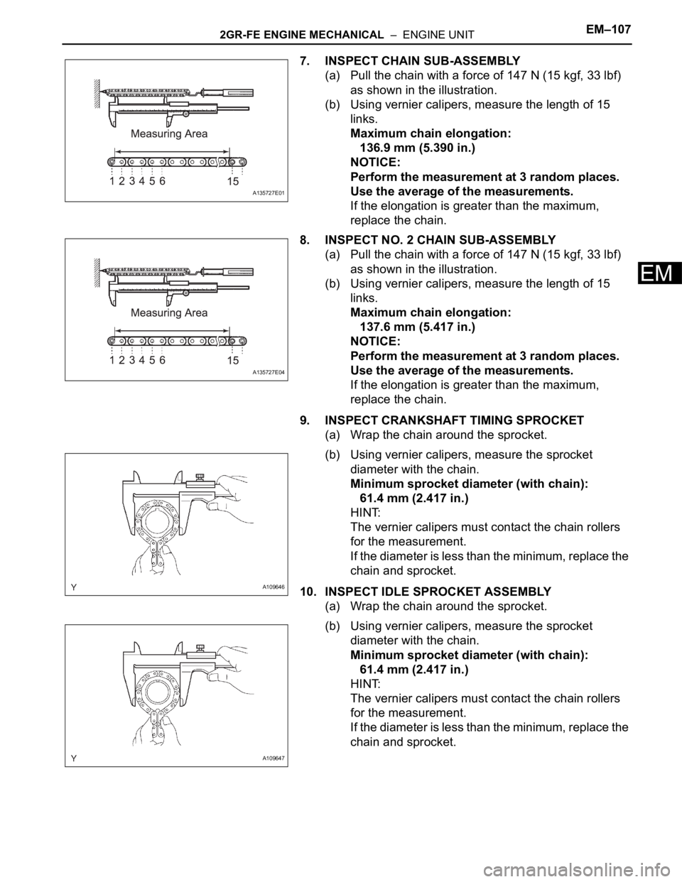
7. INSPECT CHAIN SUB-ASSEMBLY
(a) Pull the chain with a force of 147 N (15 kgf, 33 lbf)
as shown in the illustration.
(b) Using vernier calipers, measure the length of 15
links.
Maximum chain elongation:
136.9 mm (5.390 in.)
NOTICE:
Perform the measurement at 3 random places.
Use the average of the measurements.
If the elongation is greater than the maximum,
replace the chain.
8. INSPECT NO. 2 CHAIN SUB-ASSEMBLY
(a) Pull the chain with a force of 147 N (15 kgf, 33 lbf)
as shown in the illustration.
(b) Using vernier calipers, measure the length of 15
links.
Maximum chain elongation:
137.6 mm (5.417 in.)
NOTICE:
Perform the measurement at 3 random places.
Use the average of the measurements.
If the elongation is greater than the maximum,
replace the chain.
9. INSPECT CRANKSHAFT TIMING SPROCKET
(a) Wrap the chain around the sprocket.
(b) Using vernier calipers, measure the sprocket
diameter with the chain.
Minimum sprocket diameter (with chain):
61.4 mm (2.417 in.)
HINT:
The vernier calipers must contact the chain rollers
for the measurement.
If the diameter is less than the minimum, replace the
chain and sprocket.
10. INSPECT IDLE SPROCKET ASSEMBLY
(a) Wrap the chain around the sprocket.
(b) Using vernier calipers, measure the sprocket
diameter with the chain.
Minimum sprocket diameter (with chain):
61.4 mm (2.417 in.)
HINT:
The vernier calipers must contact the chain rollers
for the measurement.
If the diameter is less than the minimum, replace the
chain and sprocket.
A135727E01
A135727E04
A109646
A109647
Page 1058 of 3000
2GR-FE ENGINE MECHANICAL – ENGINE UNITEM–111
EM
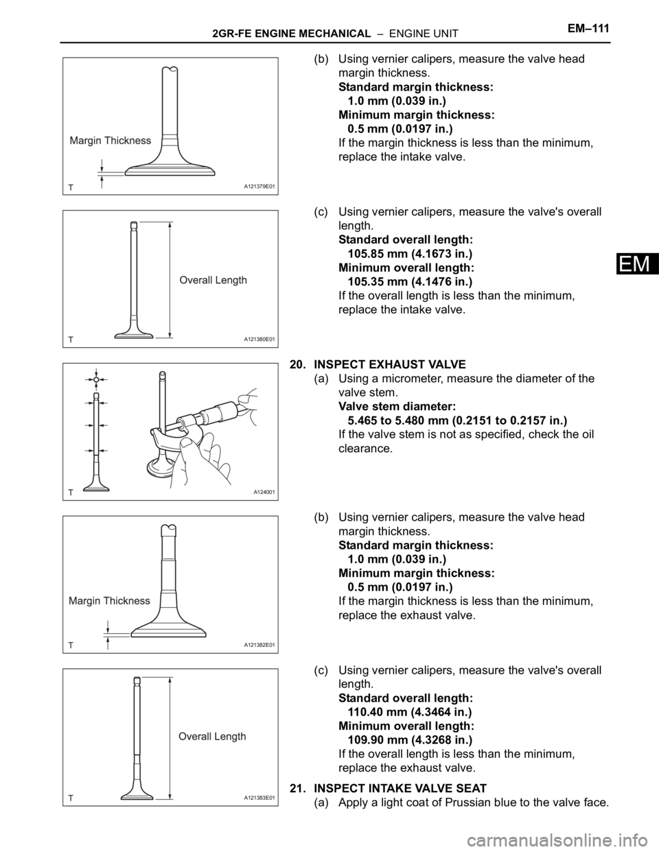
(b) Using vernier calipers, measure the valve head
margin thickness.
Standard margin thickness:
1.0 mm (0.039 in.)
Minimum margin thickness:
0.5 mm (0.0197 in.)
If the margin thickness is less than the minimum,
replace the intake valve.
(c) Using vernier calipers, measure the valve's overall
length.
Standard overall length:
105.85 mm (4.1673 in.)
Minimum overall length:
105.35 mm (4.1476 in.)
If the overall length is less than the minimum,
replace the intake valve.
20. INSPECT EXHAUST VALVE
(a) Using a micrometer, measure the diameter of the
valve stem.
Valve stem diameter:
5.465 to 5.480 mm (0.2151 to 0.2157 in.)
If the valve stem is not as specified, check the oil
clearance.
(b) Using vernier calipers, measure the valve head
margin thickness.
Standard margin thickness:
1.0 mm (0.039 in.)
Minimum margin thickness:
0.5 mm (0.0197 in.)
If the margin thickness is less than the minimum,
replace the exhaust valve.
(c) Using vernier calipers, measure the valve's overall
length.
Standard overall length:
110.40 mm (4.3464 in.)
Minimum overall length:
109.90 mm (4.3268 in.)
If the overall length is less than the minimum,
replace the exhaust valve.
21. INSPECT INTAKE VALVE SEAT
(a) Apply a light coat of Prussian blue to the valve face.
A121379E01
A121380E01
A124001
A121382E01
A121383E01
Page 1060 of 3000
2GR-FE ENGINE MECHANICAL – ENGINE UNITEM–113
EM
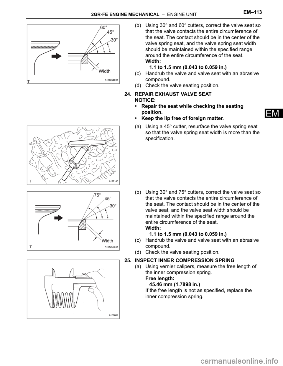
(b) Using 30 and 60 cutters, correct the valve seat so
that the valve contacts the entire circumference of
the seat. The contact should be in the center of the
valve spring seat, and the valve spring seat width
should be maintained within the specified range
around the entire circumference of the seat.
Width:
1.1 to 1.5 mm (0.043 to 0.059 in.)
(c) Handrub the valve and valve seat with an abrasive
compound.
(d) Check the valve seating position.
24. REPAIR EXHAUST VALVE SEAT
NOTICE:
• Repair the seat while checking the seating
position.
• Keep the lip free of foreign matter.
(a) Using a 45
cutter, resurface the valve spring seat
so that the valve spring seat width is more than the
specification.
(b) Using 30
and 75 cutters, correct the valve seat so
that the valve contacts the entire circumference of
the seat. The contact should be in the center of the
valve seat, and the valve seat width should be
maintained within the specified range around the
entire circumference of the seat.
Width:
1.1 to 1.5 mm (0.043 to 0.059 in.)
(c) Handrub the valve and valve seat with an abrasive
compound.
(d) Check the valve seating position.
25. INSPECT INNER COMPRESSION SPRING
(a) Using vernier calipers, measure the free length of
the inner compression spring.
Free length:
45.46 mm (1.7898 in.)
If the free length is not as specified, replace the
inner compression spring.
A124254E01
A127140
A124255E01
A109669
Page 1078 of 3000
2GR-FE ENGINE MECHANICAL – ENGINE UNITEM–131
EM
(b) Confirm the projection and numbers of the main
bearing caps and install the bearing caps on the
cylinder block.
HINT:
A number is marked on each main bearing cap to
indicate the installation position.
(c) Apply a light coat of engine oil to the threads and
under the heads of the crankshaft bearing cap bolts.
(d) Temporarily install the 8 crankshaft bearing cap
bolts to the inside positions.
(e) Insert the crankshaft bearing cap with your hand
until the clearance between the crankshaft bearing
cap and the cylinder block is less than 6 mm (0.23
in.) by marking the 2 internal crankshaft bearing cap
bolts as a guide.
Bolt length:
100 to 102 mm (3.94 to 4.02 in.)
(f) Using a plastic hammer, lightly tap the crankshaft
bearing cap to ensure a proper fit.
(g) Apply a light coat of engine oil to the threads and
under the heads of the 8 crankshaft bearing cap
bolts.
A121711E02
A134893E01
A131829
Page 1079 of 3000
EM–1322GR-FE ENGINE MECHANICAL – ENGINE UNIT
EM
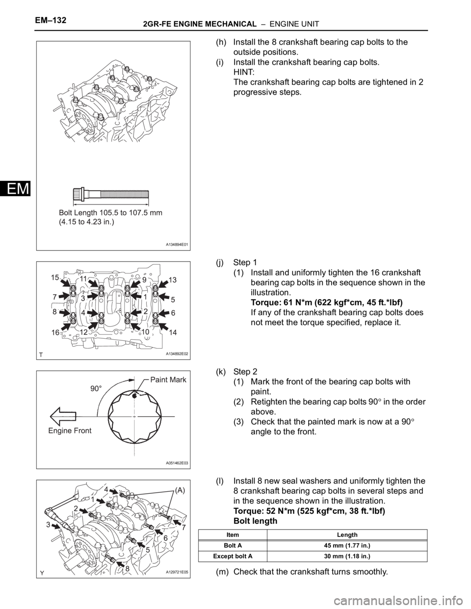
(h) Install the 8 crankshaft bearing cap bolts to the
outside positions.
(i) Install the crankshaft bearing cap bolts.
HINT:
The crankshaft bearing cap bolts are tightened in 2
progressive steps.
(j) Step 1
(1) Install and uniformly tighten the 16 crankshaft
bearing cap bolts in the sequence shown in the
illustration.
Torque: 61 N*m (622 kgf*cm, 45 ft.*lbf)
If any of the crankshaft bearing cap bolts does
not meet the torque specified, replace it.
(k) Step 2
(1) Mark the front of the bearing cap bolts with
paint.
(2) Retighten the bearing cap bolts 90
in the order
above.
(3) Check that the painted mark is now at a 90
angle to the front.
(l) Install 8 new seal washers and uniformly tighten the
8 crankshaft bearing cap bolts in several steps and
in the sequence shown in the illustration.
Torque: 52 N*m (525 kgf*cm, 38 ft.*lbf)
Bolt length
(m) Check that the crankshaft turns smoothly.
A134894E01
A134892E02
A051462E03
A129721E05
Item Length
Bolt A 45 mm (1.77 in.)
Except bolt A 30 mm (1.18 in.)
Page 1104 of 3000
2GR-FE ENGINE MECHANICAL – ENGINE UNITEM–157
EM
Bolt length
NOTICE:
Make sure that there is no oil on the bolt and nut
threads.
(f) Fully tighten the bolts in this order: Area 1 and Area
2.
Torque: 21 N*m (214 kgf*cm, 15 ft.*lbf)
(g) Fully tighten the bolts in Area 3.
Torque: 21 N*m (214 kgf*cm, 15 ft.*lbf)
HINT:
Tighten the bolts and nuts in the order of upper to
lower as shown in the illustration.
(h) Fully tighten the bolts in Area 4.
Torque: 43 N*m (438 kgf*cm, 32 ft.*lbf) for bolt A
21 N*m (214 kgf*cm, 15 ft.*lbf) for bolts
except bolt A
HINT:
Tighten the bolts in the order of lower to upper as
shown in the illustration.
(i) Install a new chain cover plate gasket and the chain
cover plate with the 4 bolts.
Torque: 9.1 N*m (93 kgf*cm, 81 in.*lbf)
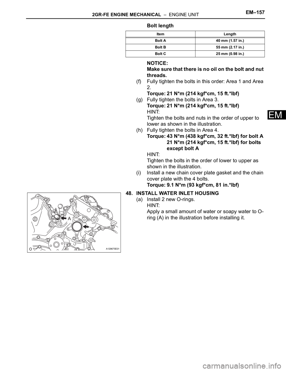
48. INSTALL WATER INLET HOUSING
(a) Install 2 new O-rings.
HINT:
Apply a small amount of water or soapy water to O-
ring (A) in the illustration before installing it.
Item Length
Bolt A 40 mm (1.57 in.)
Bolt B 55 mm (2.17 in.)
Bolt C 25 mm (0.98 in.)
A129675E01
Page 1177 of 3000
2GR-FE EMISSION CONTROL – AIR FUEL RATIO SENSOR (for 2WD)EC–21
EC
INSTALLATION
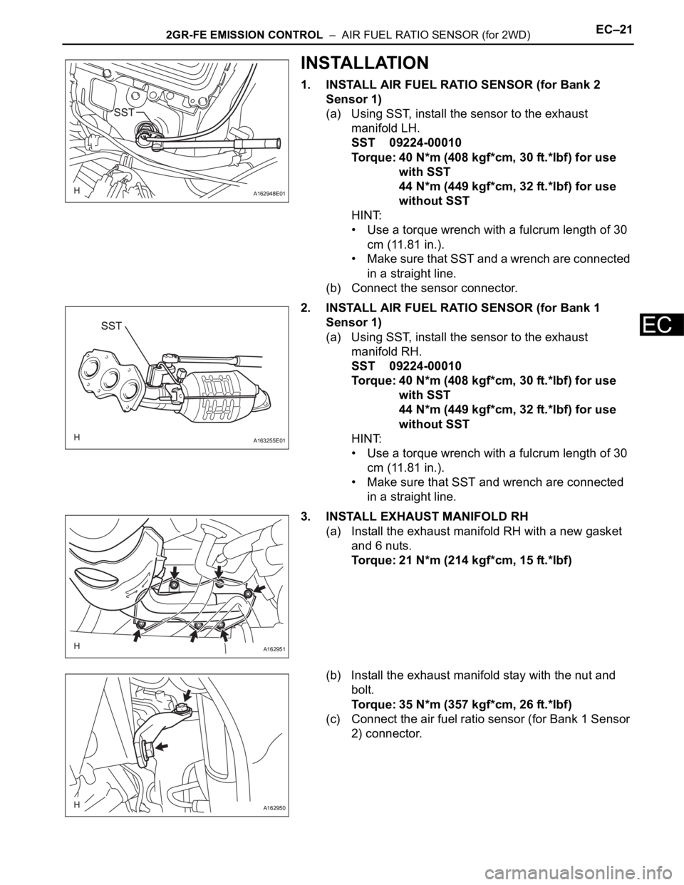
1. INSTALL AIR FUEL RATIO SENSOR (for Bank 2
Sensor 1)
(a) Using SST, install the sensor to the exhaust
manifold LH.
SST 09224-00010
Torque: 40 N*m (408 kgf*cm, 30 ft.*lbf) for use
with SST
44 N*m (449 kgf*cm, 32 ft.*lbf) for use
without SST
HINT:
• Use a torque wrench with a fulcrum length of 30
cm (11.81 in.).
• Make sure that SST and a wrench are connected
in a straight line.
(b) Connect the sensor connector.
2. INSTALL AIR FUEL RATIO SENSOR (for Bank 1
Sensor 1)
(a) Using SST, install the sensor to the exhaust
manifold RH.
SST 09224-00010
Torque: 40 N*m (408 kgf*cm, 30 ft.*lbf) for use
with SST
44 N*m (449 kgf*cm, 32 ft.*lbf) for use
without SST
HINT:
• Use a torque wrench with a fulcrum length of 30
cm (11.81 in.).
• Make sure that SST and wrench are connected
in a straight line.
3. INSTALL EXHAUST MANIFOLD RH
(a) Install the exhaust manifold RH with a new gasket
and 6 nuts.
Torque: 21 N*m (214 kgf*cm, 15 ft.*lbf)
(b) Install the exhaust manifold stay with the nut and
bolt.
Torque: 35 N*m (357 kgf*cm, 26 ft.*lbf)
(c) Connect the air fuel ratio sensor (for Bank 1 Sensor
2) connector.
A162948E01
A163255E01
A162951
A162950