2007 TOYOTA SIENNA length
[x] Cancel search: lengthPage 226 of 3000

SERVICE SPECIFICATIONS – U151F AUTOMATIC TRANSAXLESS–33
SS
Reverse clutch
Pack clearance:0.60 to 0.82 mm (0.02362 to 0.03228 in.)
Flange thickness Mark
1 3.0 mm (0.118 in.)
2 3.1 mm (0.122 in.)
3 3.2 mm (0.126 in.)
4 3.3 mm (0.130 in.)
5 3.4 mm (0.134 in.)
6 3.5 mm (0.138 in.)
7 3.6 mm (0.142 in.)
Direct clutch & O/D clutch
Pack clearance0.61 to 0.83 mm (0.02401 to 0.03268 in.)
Return spring free length25.91 mm (1.0201 in.)
Flange thickness Mark
0 2.5 mm (0.098 in.)
1 2.6 mm (0.102 in.)
2 2.7 mm (0.106 in.)
3 2.8 mm (0.110 in.)
4 2.9 mm (0.114 in.)
5 3.0 mm (0.118 in.)
6 3.1 mm (0.122 in.)
2nd brake
Pack clearance0.62 to 0.91 mm (0.0244 to 0.0358 in.)
Return spring free length16.61 mm (0.6539 in.)
Flange thickness Mark
1 3.0 mm (0.118 in.)
2 3.1 mm (0.122 in.)
3 3.2 mm (0.126 in.)
4 3.3 mm (0.130 in.)
5 3.4 mm (0.134 in.)
6 3.5 mm (0.138 in.)
7 3.6 mm (0.142 in.)
U/D clutch
Pack clearance1.51 to 1.71 mm (0.0594 to 0.0673 in.)
U/D clutch drum bushing inside diameter STD 37.06 to 37.08 mm (1.4591 to 1.4598 in.)
Max. 37.13 mm (1.4618 in.)
Return spring free length17.14 mm (0.6752 in.)
Flange thickness Mark
1 3.0 mm (0.118 in.)
2 3.1 mm (0.122 in.)
3 3.2 mm (0.126 in.)
4 3.3 mm (0.130 in.)
5 3.4 mm (0.134 in.)
U/D brake
Pack clearance1.81 to 2.20 mm (0.0713 to 0.0866 in.)
Return spring free length14.04 mm (0.5528 in.)
Page 227 of 3000

SS–34SERVICE SPECIFICATIONS – U151F AUTOMATIC TRANSAXLE
SS
Flange thickness Mark
1 3.0 mm (0.118 in.)
2 3.2 mm (0.126 in.)
3 3.4 mm (0.134 in.)
1st & reverse brake
Pack clearance1.16 to 1.35 mm (0.0457 to 0.0531in.)
Return spring free length15.53 mm (0.6114 in.)
Flange thickness Mark
1 1.8 mm (0.071 in.)
2 1.9 mm (0.075 in.)
3 2.0 mm (0.079 in.)
4 2.1 mm (0.083 in.)
5 2.2 mm (0.087 in.)
6 2.3 mm (0.091 in.)
7 2.4 mm (0.094 in.)
8 2.5 mm (0.098 in.)
U/D planetary gear
Preload (at 60 rpm) 0.50 to 1.42 N*m (5.1 to 14.5 kgf*cm, 0.06 to 0.17 in.*lbf)
Front planetary gear
Turning torque (at 60 rpm) New
Bearing0.51 to 1.02 N*m (5.1 to 10.0 kgf*cm, 4.4 to 8.7 in.*lbf)
Used
Bearing0.26 to 0.51 N*m (2.7 to 5.2 kgf*cm, 2.3 to 4.5 in.*lbf)
Input shaft
End play0.262 to 1.249 mm (0.0103 to 0.0492 in.)
Transaxle rear cover
Bearing press fit depth 20.55 to 21.25 mm (0.8091 to 0.8366 in.)
Transmission valve body
Valve body installation bolt length A 41 mm (1.614 in.)
B 57 mm (2.244 in.)
C 25 mm (0.984 in.)
Accumulator
Spring Free length/Outer diameter Color
B
3Inner 62.00 (2.4409) / 15.50 (0.610) Purple
Outer 74.23 (2.9224) / 16.50 (0.649) Purple
C
260.96 (2.3999) / 14.10 (0.555) Yellow
C
372.20 (2.8425) / 19.0 (0.748) Colorless
Front differential (U151F)
Side gear backlash 0.05 to 0.20 mm (0.0020 to 0.0079 in.) U/D brake
Page 326 of 3000

ES–2582GR-FE ENGINE CONTROL SYSTEM – SFI SYSTEM
ES
MONITOR DESCRIPTION
The ECM uses the sensors mounted in front of and behind the three-way catalyst (TWC) to monitor its
efficiency. The first sensor, an Air Fuel ratio (A/F) sensor, sends pre-catalyst A/F ratio information to the
ECM. The second sensor, a heated oxygen sensor (O2S), sends post-catalyst information to the ECM.
The ECM compares these 2 signals to judge the efficiency of the catalyst and the catalyst's ability to store
oxygen. During normal operation, the TWC stores and releases oxygen as needed. The capacity to store
oxygen results in a low variation in the post-TWC exhaust stream.
If the catalyst is functioning normally, the waveform of the heated oxygen sensor slowly switches between
RICH and LEAN. If the catalyst is deteriorated, the waveform will alternate frequently between RICH and
LEAN. As the catalyst efficiency degrades, its ability to store oxygen is reduced and the catalyst output
becomes more variable. When running the monitor, the ECM compares sensor 1 signals (A/F sensor)
over a specific amount of time to determine catalyst efficiency. The ECM begins by calculating the signal
length for both sensors (for the rear oxygen sensor, the ECM uses the output voltage signal length). If the
oxygen sensor output voltage signal length is greater than the threshold (threshold is calculated based on
the A/F sensor signal length), the ECM concludes that the catalyst is malfunctioning. The ECM will turn on
the MIL and a DTC will be set.
HINT:
• Bank 1 refers to the bank that includes cylinder No. 1.
• Bank 2 refers to the bank that does not include cylinder No. 1.
• Sensor 1 refers to the sensor closest to the engine assembly.
• Sensor 2 refers to the sensor farthest away from the engine assembly.
MONITOR STRATEGY
DTC P0420Catalyst System Efficiency Below Threshold
(Bank 1)
DTC P0430Catalyst System Efficiency Below Threshold
(Bank 2)
DTC No. DTC Detection Condition Trouble Area
P0420Oxygen Storage Capacity (OSC) value is smaller than
standard value under active air-fuel ratio control (2 trip
detection logic)• Gas leakage from exhaust system
• A/F sensor (bank 1 sensor 1)
• HO2 sensor (bank 1 sensor 2)
• Exhaust manifold (TWC)
P0430OSC value is smaller than standard value under active
air-fuel ratio control (2 trip detection logic)• Gas leakage from exhaust system
• A/F sensor (bank 2 sensor 1)
• HO2 sensor (bank 2 sensor 2)
• Exhaust manifold (TWC)
Related DTCsP0420: Catalyst Deterioration
P0430: Catalyst Deterioration
Required Sensors / Components (Main) TWC
Required Sensors / Components (Related)A/F sensor, heated oxygen sensor, intake air temperature sensor, mass air flow
meter, crankshaft position sensor and engine coolant temperature sensor
Frequency of Operation Once per driving cycle
Duration Approximately 30 seconds
MIL Operation 2 driving cycles
Sequence of Operation None
Page 817 of 3000
2GR-FE ENGINE CONTROL SYSTEM – SFI SYSTEMES–37
ES
*1: The ECM terminal voltage is constant regardless of
the output voltage from the sensor.
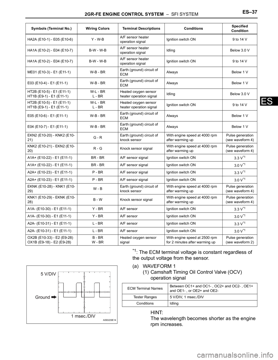
(a) WAVEFORM 1
(1) Camshaft Timing Oil Control Valve (OCV)
operation signal
HINT:
The wavelength becomes shorter as the engine
rpm increases.
HA2A (E10-1) - E05 (E10-6) Y - W-BA/F sensor heater
operation signalIgnition switch ON 9 to 14 V
HA1A (E10-2) - E04 (E10-7) B-W - W-BA/F sensor heater
operation signalIdling Below 3.0 V
HA1A (E10-2) - E04 (E10-7) B-W - W-BA/F sensor heater
operation signalIgnition switch ON 9 to 14 V
ME01 (E10-3) - E1 (E11-1) W-B - BREarth (ground) circuit of
ECMAlways Below 1 V
E03 (E10-4) - E1 (E11-1) W-B - BREarth (ground) circuit of
ECMAlways Below 1 V
HT2B (E10-5) - E1 (E11-1)
HT1B (E9-1) - E1 (E11-1)W-L - BR
L - BRHeated oxygen sensor
heater operation signalIdling Below 3.0 V
HT2B (E10-5) - E1 (E11-1)
HT1B (E9-1) - E1 (E11-1)W-L - BR
L - BRHeated oxygen sensor
heater operation signalIgnition switch ON 9 to 14 V
E05 (E10-6) - E1 (E11-1) W-B - BREarth (ground) circuit of
ECMAlways Below 1 V
E04 (E10-7) - E1 (E11-1) W-B - BREarth (ground) circuit of
ECMAlways Below 1 V
EKN2 (E10-20) - KNK2 (E10-
21)G - REarth (ground) circuit of
knock sensorWith engine speed at 4000 rpm
after warming upPulse generation
(see waveform 4)
KNK2 (E10-21) - EKN2 (E10-
20)R - G Knock sensor signalWith engine speed at 4000 rpm
after warming upPulse generation
(see waveform 4)
A1A+ (E10-22) - E1 (E11-1) BR - BR A/F sensor signal Ignition switch ON
3.3 V
*1
A1A+ (E10-22) - E1 (E11-1) BR - BR A/F sensor signal Ignition switch ON
3.0 V*1
A2A+ (E10-23) - E1 (E11-1) P - BR A/F sensor signal Ignition switch ON
3.3 V*1
A2A+ (E10-23) - E1 (E11-1) P - BR A/F sensor signal Ignition switch ON
3.0 V*1
EKNK (E10-28) - KNK1 (E10-
29)W - BEarth (ground) circuit of
knock sensorWith engine speed at 4000 rpm
after warming upPulse generation
(see waveform 4)
KNK1 (E10-29) - EKNK (E10-
28)B - W Knock sensor signalWith engine speed at 4000 rpm
after warming upPulse generation
(see waveform 4)
A1A- (E10-30) - E1 (E11-1) Y - BR A/F sensor Ignition switch ON
3.3 V
*1
A1A- (E10-30) - E1 (E11-1) Y - BR A/F sensor Ignition switch ON
3.0 V*1
A2A- (E10-31) - E1 (E11-1) L - BR A/F sensor Ignition switch ON
3.3 V*1
A2A- (E10-31) - E1 (E11-1) L - BR A/F sensor Ignition switch ON
3.0 V*1
OX2B (E10-33) - E2 (E9-28)
OX1B (E9-18) - E2 (E9-28)B - BR
W - BRHeated oxygen sensor
signalWith engine speed at 2500 rpm
for 2 minutes after warming upPulse generation
(see waveform 2) Symbols (Terminal No.) Wiring Colors Terminal Descriptions ConditionsSpecified
Condition
A093229E14
ECM Terminal NamesBetween OC1+ and OC1- , OC2+ and OC2- , OE1+
and OE1- , or OE2+ and OE2-
Tester Ranges 5 V/DIV, 1 msec./DIV
Conditions Idling
Page 818 of 3000
ES–382GR-FE ENGINE CONTROL SYSTEM – SFI SYSTEM
ES
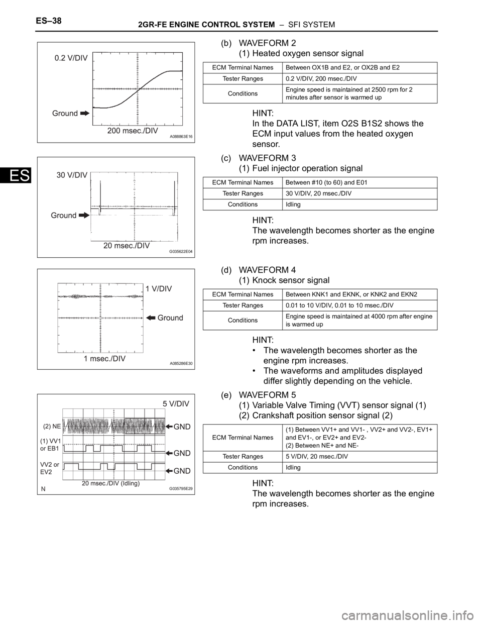
(b) WAVEFORM 2
(1) Heated oxygen sensor signal
HINT:
In the DATA LIST, item O2S B1S2 shows the
ECM input values from the heated oxygen
sensor.
(c) WAVEFORM 3
(1) Fuel injector operation signal
HINT:
The wavelength becomes shorter as the engine
rpm increases.
(d) WAVEFORM 4
(1) Knock sensor signal
HINT:
• The wavelength becomes shorter as the
engine rpm increases.
• The waveforms and amplitudes displayed
differ slightly depending on the vehicle.
(e) WAVEFORM 5
(1) Variable Valve Timing (VVT) sensor signal (1)
(2) Crankshaft position sensor signal (2)
HINT:
The wavelength becomes shorter as the engine
rpm increases.
A088863E16
ECM Terminal Names Between OX1B and E2, or OX2B and E2
Tester Ranges 0.2 V/DIV, 200 msec./DIV
ConditionsEngine speed is maintained at 2500 rpm for 2
minutes after sensor is warmed up
G035622E04
ECM Terminal Names Between #10 (to 60) and E01
Tester Ranges 30 V/DIV, 20 msec./DIV
Conditions Idling
A085286E30
ECM Terminal Names Between KNK1 and EKNK, or KNK2 and EKN2
Tester Ranges 0.01 to 10 V/DIV, 0.01 to 10 msec./DIV
ConditionsEngine speed is maintained at 4000 rpm after engine
is warmed up
G035795E29
ECM Terminal Names(1) Between VV1+ and VV1- , VV2+ and VV2-, EV1+
and EV1-, or EV2+ and EV2-
(2) Between NE+ and NE-
Tester Ranges 5 V/DIV, 20 msec./DIV
Conditions Idling
Page 819 of 3000
2GR-FE ENGINE CONTROL SYSTEM – SFI SYSTEMES–39
ES
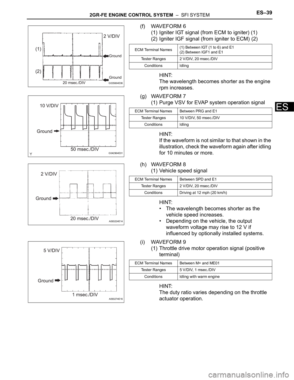
(f) WAVEFORM 6
(1) Igniter IGT signal (from ECM to igniter) (1)
(2) Igniter IGF signal (from igniter to ECM) (2)
HINT:
The wavelength becomes shorter as the engine
rpm increases.
(g) WAVEFORM 7
(1) Purge VSV for EVAP system operation signal
HINT:
If the waveform is not similar to that shown in the
illustration, check the waveform again after idling
for 10 minutes or more.
(h) WAVEFORM 8
(1) Vehicle speed signal
HINT:
• The wavelength becomes shorter as the
vehicle speed increases.
• Depending on the vehicle, the output
waveform voltage may rise to 12 V if
influenced by optionally installed systems.
(i) WAVEFORM 9
(1) Throttle drive motor operation signal (positive
terminal)
HINT:
The duty ratio varies depending on the throttle
actuator operation.
G035664E06
ECM Terminal Names(1) Between IGT (1 to 6) and E1
(2) Between IGF1 and E1
Tester Ranges 2 V/DIV, 20 msec./DIV
Conditions Idling
G042964E01
ECM Terminal Names Between PRG and E1
Tester Ranges 10 V/DIV, 50 msec./DIV
Conditions Idling
A093224E14
ECM Terminal Names Between SPD and E1
Tester Ranges 2 V/DIV, 20 msec./DIV
Conditions Driving at 12 mph (20 km/h)
A093274E16
ECM Terminal Names Between M+ and ME01
Tester Ranges 5 V/DIV, 1 msec./DIV
Conditions Idling with warm engine
Page 820 of 3000
ES–402GR-FE ENGINE CONTROL SYSTEM – SFI SYSTEM
ES
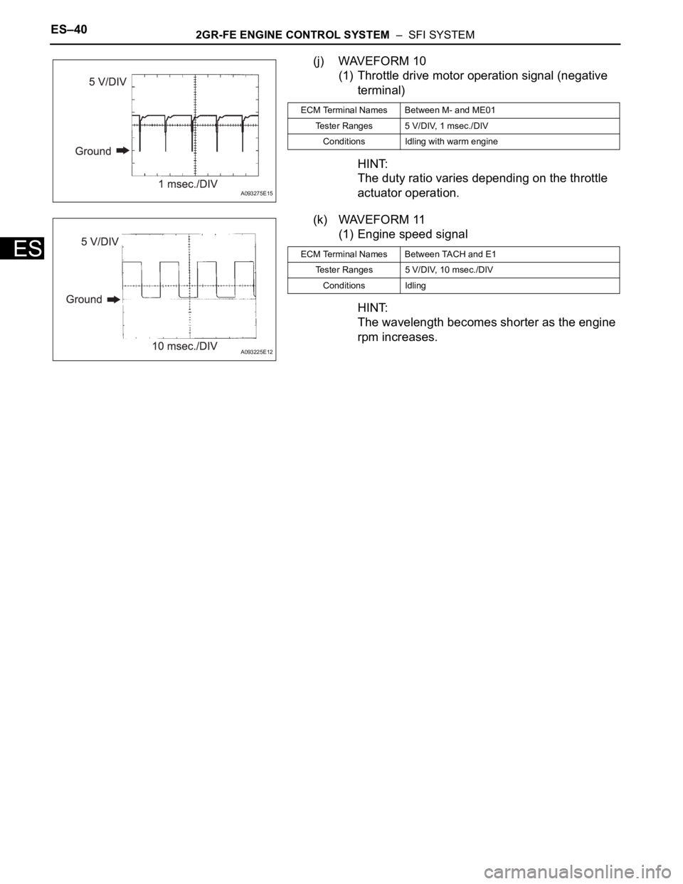
(j) WAVEFORM 10
(1) Throttle drive motor operation signal (negative
terminal)
HINT:
The duty ratio varies depending on the throttle
actuator operation.
(k) WAVEFORM 11
(1) Engine speed signal
HINT:
The wavelength becomes shorter as the engine
rpm increases.
A093275E15
ECM Terminal Names Between M- and ME01
Tester Ranges 5 V/DIV, 1 msec./DIV
Conditions Idling with warm engine
A093225E12
ECM Terminal Names Between TACH and E1
Tester Ranges 5 V/DIV, 10 msec./DIV
Conditions Idling
Page 842 of 3000
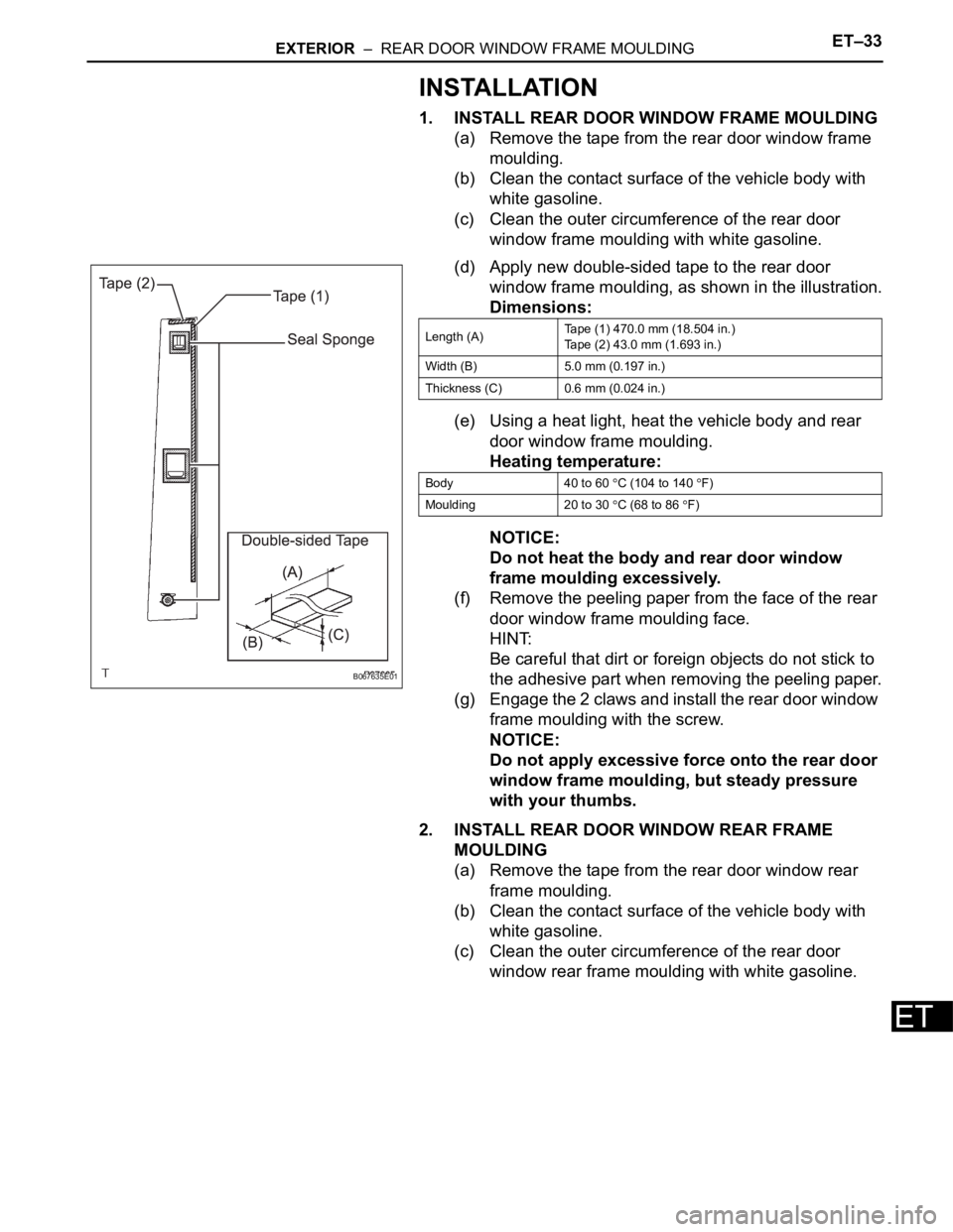
EXTERIOR – REAR DOOR WINDOW FRAME MOULDINGET–33
ET
INSTALLATION
1. INSTALL REAR DOOR WINDOW FRAME MOULDING
(a) Remove the tape from the rear door window frame
moulding.
(b) Clean the contact surface of the vehicle body with
white gasoline.
(c) Clean the outer circumference of the rear door
window frame moulding with white gasoline.
(d) Apply new double-sided tape to the rear door
window frame moulding, as shown in the illustration.
Dimensions:
(e) Using a heat light, heat the vehicle body and rear
door window frame moulding.
Heating temperature:
NOTICE:
Do not heat the body and rear door window
frame moulding excessively.
(f) Remove the peeling paper from the face of the rear
door window frame moulding face.
HINT:
Be careful that dirt or foreign objects do not stick to
the adhesive part when removing the peeling paper.
(g) Engage the 2 claws and install the rear door window
frame moulding with the screw.
NOTICE:
Do not apply excessive force onto the rear door
window frame moulding, but steady pressure
with your thumbs.
2. INSTALL REAR DOOR WINDOW REAR FRAME
MOULDING
(a) Remove the tape from the rear door window rear
frame moulding.
(b) Clean the contact surface of the vehicle body with
white gasoline.
(c) Clean the outer circumference of the rear door
window rear frame moulding with white gasoline.
B067635E01
Length (A)Tape (1) 470.0 mm (18.504 in.)
Tape (2) 43.0 mm (1.693 in.)
Width (B) 5.0 mm (0.197 in.)
Thickness (C) 0.6 mm (0.024 in.)
Body 40 to 60
C (104 to 140 F)
Moulding 20 to 30
C (68 to 86 F)