Page 1333 of 3000
ST–102GR-FE STARTING – STARTER
ST
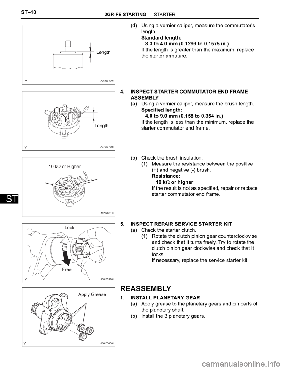
(d) Using a vernier caliper, measure the commutator's
length.
Standard length:
3.3 to 4.0 mm (0.1299 to 0.1575 in.)
If the length is greater than the maximum, replace
the starter armature.
4. INSPECT STARTER COMMUTATOR END FRAME
ASSEMBLY
(a) Using a vernier caliper, measure the brush length.
Specified length:
4.0 to 9.0 mm (0.158 to 0.354 in.)
If the length is less than the minimum, replace the
starter commutator end frame.
(b) Check the brush insulation.
(1) Measure the resistance between the positive
(+) and negative (-) brush.
Resistance:
10 k
or higher
If the result is not as specified, repair or replace
starter commutator end frame.
5. INSPECT REPAIR SERVICE STARTER KIT
(a) Check the starter clutch.
(1) Rotate the clutch pinion gear counterclockwise
and check that it turns freely. Try to rotate the
clutch pinion gear clockwise and check that it
locks.
If necessary, replace the service starter kit.
REASSEMBLY
1. INSTALL PLANETARY GEAR
(a) Apply grease to the planetary gears and pin parts of
the planetary shaft.
(b) Install the 3 planetary gears.
A058584E01
A076677E01
A079766E11
A081655E01
A081656E01
Page 1334 of 3000
2GR-FE STARTING – STARTERST–11
ST
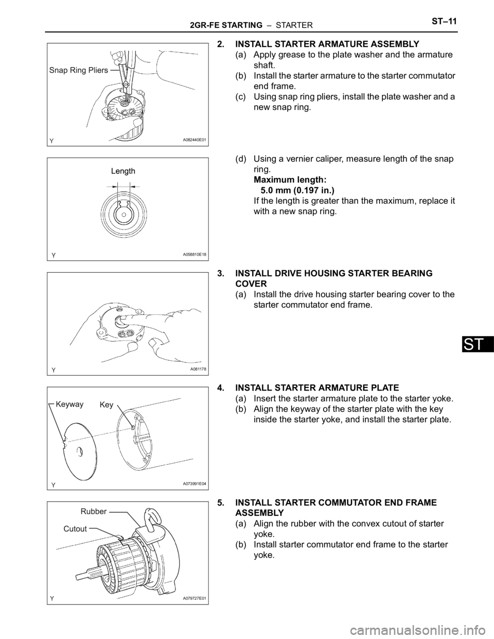
2. INSTALL STARTER ARMATURE ASSEMBLY
(a) Apply grease to the plate washer and the armature
shaft.
(b) Install the starter armature to the starter commutator
end frame.
(c) Using snap ring pliers, install the plate washer and a
new snap ring.
(d) Using a vernier caliper, measure length of the snap
ring.
Maximum length:
5.0 mm (0.197 in.)
If the length is greater than the maximum, replace it
with a new snap ring.
3. INSTALL DRIVE HOUSING STARTER BEARING
COVER
(a) Install the drive housing starter bearing cover to the
starter commutator end frame.
4. INSTALL STARTER ARMATURE PLATE
(a) Insert the starter armature plate to the starter yoke.
(b) Align the keyway of the starter plate with the key
inside the starter yoke, and install the starter plate.
5. INSTALL STARTER COMMUTATOR END FRAME
ASSEMBLY
(a) Align the rubber with the convex cutout of starter
yoke.
(b) Install starter commutator end frame to the starter
yoke.
A082440E01
A058810E18
A081178
A073991E04
A079727E01
Page 1361 of 3000
2GR-FE CHARGING – GENERATORCH–21
CH
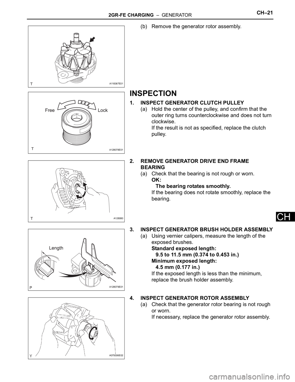
(b) Remove the generator rotor assembly.
INSPECTION
1. INSPECT GENERATOR CLUTCH PULLEY
(a) Hold the center of the pulley, and confirm that the
outer ring turns counterclockwise and does not turn
clockwise.
If the result is not as specified, replace the clutch
pulley.
2. REMOVE GENERATOR DRIVE END FRAME
BEARING
(a) Check that the bearing is not rough or worn.
OK:
The bearing rotates smoothly.
If the bearing does not rotate smoothly, replace the
bearing.
3. INSPECT GENERATOR BRUSH HOLDER ASSEMBLY
(a) Using vernier calipers, measure the length of the
exposed brushes.
Standard exposed length:
9.5 to 11.5 mm (0.374 to 0.453 in.)
Minimum exposed length:
4.5 mm (0.177 in.)
If the exposed length is less than the minimum,
replace the brush holder assembly.
4. INSPECT GENERATOR ROTOR ASSEMBLY
(a) Check that the generator rotor bearing is not rough
or worn.
If necessary, replace the generator rotor assembly.
A118367E01
A128078E01
A128080
A128079E01
A079306E02
Page 1367 of 3000
2GR-FE CHARGING – GENERATORCH–27
CH
(f) Tighten the pulley by turning SST (B) in the direction
shown in the illustration.
Torque: without SST
110 N*m (1125 kgf*cm, 81 ft.*lbf)
with SST
84 N*m (857 kgf*cm, 62 ft.*lbf)
NOTICE:
• Use a torque wrench with a fulcrum length of
318 mm (12.52 in.).
• This torque value is effective when SST is
parallel to a torque wrench.
• Hold the generator assembly tightly.
(g) Remove the generator assembly from SST.
(h) Check that the clutch pulley rotates smoothly.
(i) Install a new clutch pulley cap to the clutch pulley.
INSTALLATION
1. INSTALL GENERATOR ASSEMBLY
(a) Install the bracket with the bolt.
Torque: 20 N*m (204 kgf*cm, 15 ft.*lbf)
(b) Install the wire harness clamp stay.
Torque: 8.4 N*m (86 kgf*cm, 74 in.*lbf)
(c) Connect the wire harness clamp.
(d) Install the generator assembly to the cylinder block
with the bolt.
Torque: 20 N*m (204 kgf*cm, 15 ft.*lbf)
A151433E01
A135391
A128066
A162683E01
Page 1370 of 3000
2GR-FE CHARGING – GENERATORCH–21
CH
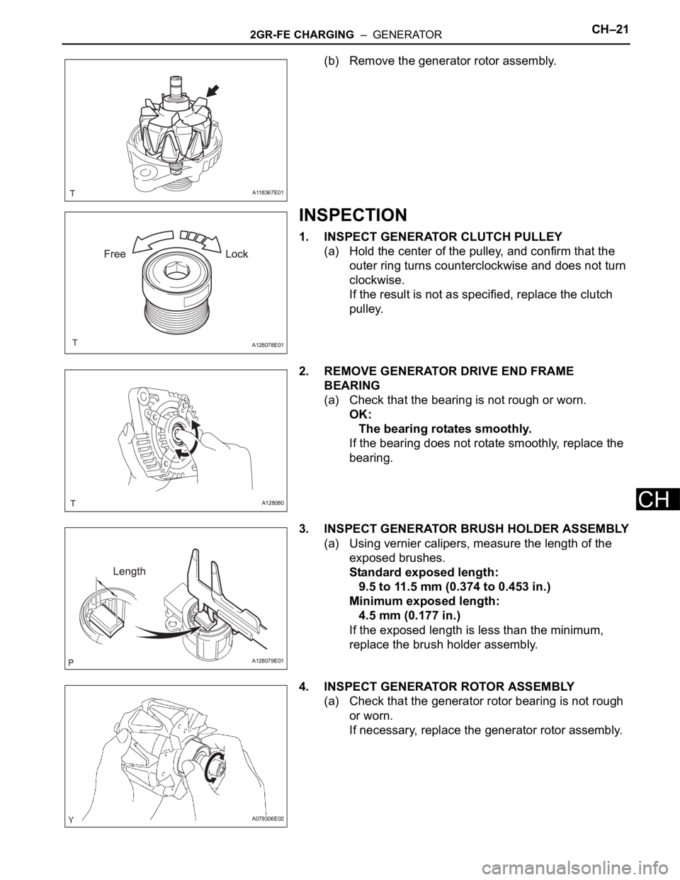
(b) Remove the generator rotor assembly.
INSPECTION
1. INSPECT GENERATOR CLUTCH PULLEY
(a) Hold the center of the pulley, and confirm that the
outer ring turns counterclockwise and does not turn
clockwise.
If the result is not as specified, replace the clutch
pulley.
2. REMOVE GENERATOR DRIVE END FRAME
BEARING
(a) Check that the bearing is not rough or worn.
OK:
The bearing rotates smoothly.
If the bearing does not rotate smoothly, replace the
bearing.
3. INSPECT GENERATOR BRUSH HOLDER ASSEMBLY
(a) Using vernier calipers, measure the length of the
exposed brushes.
Standard exposed length:
9.5 to 11.5 mm (0.374 to 0.453 in.)
Minimum exposed length:
4.5 mm (0.177 in.)
If the exposed length is less than the minimum,
replace the brush holder assembly.
4. INSPECT GENERATOR ROTOR ASSEMBLY
(a) Check that the generator rotor bearing is not rough
or worn.
If necessary, replace the generator rotor assembly.
A118367E01
A128078E01
A128080
A128079E01
A079306E02
Page 1376 of 3000
2GR-FE CHARGING – GENERATORCH–27
CH
(f) Tighten the pulley by turning SST (B) in the direction
shown in the illustration.
Torque: without SST
110 N*m (1125 kgf*cm, 81 ft.*lbf)
with SST
84 N*m (857 kgf*cm, 62 ft.*lbf)
NOTICE:
• Use a torque wrench with a fulcrum length of
318 mm (12.52 in.).
• This torque value is effective when SST is
parallel to a torque wrench.
• Hold the generator assembly tightly.
(g) Remove the generator assembly from SST.
(h) Check that the clutch pulley rotates smoothly.
(i) Install a new clutch pulley cap to the clutch pulley.
INSTALLATION
1. INSTALL GENERATOR ASSEMBLY
(a) Install the bracket with the bolt.
Torque: 20 N*m (204 kgf*cm, 15 ft.*lbf)
(b) Install the wire harness clamp stay.
Torque: 8.4 N*m (86 kgf*cm, 74 in.*lbf)
(c) Connect the wire harness clamp.
(d) Install the generator assembly to the cylinder block
with the bolt.
Torque: 20 N*m (204 kgf*cm, 15 ft.*lbf)
A151433E01
A135391
A128066
A162683E01
Page 1523 of 3000
AX–140U151E AUTOMATIC TRANSAXLE – VALVE BODY ASSEMBLY
AX
(f) Install the shift solenoid valve SL3 and SLT to the
valve body assembly.
(g) Install the lock plate to the valve body assembly with
the bolt.
Torque: 6.6 N*m (67 kgf*cm, 58 in.*lbf)
(h) Install the spring and check ball body.
(i) Align the groove of the manual valve with the pin of
the lever.
(j) Install the 17 bolts.
Torque: 11 N*m (110 kgf*cm, 8 ft.*lbf)
NOTICE:
• Push the valve body against the accumulator
piston springs and check ball body to install
the valve body.
• First, temporarily tighten the bolts marked
with (1) in the illustration because they are
positioning bolts.
Bolt length:
Bolt A:
41 mm (1.614 in.)
Bolt B:
57 mm (2.244 in.)
Bolt C:
25 mm (0.984 in.)
2. INSTALL VALVE BODY OIL STRAINER ASSEMBLY
(a) Coat a new O-ring with ATF.
(b) Install the O-ring to the oil strainer.
C089112
C050017
C091933E05
C091932
Page 1577 of 3000
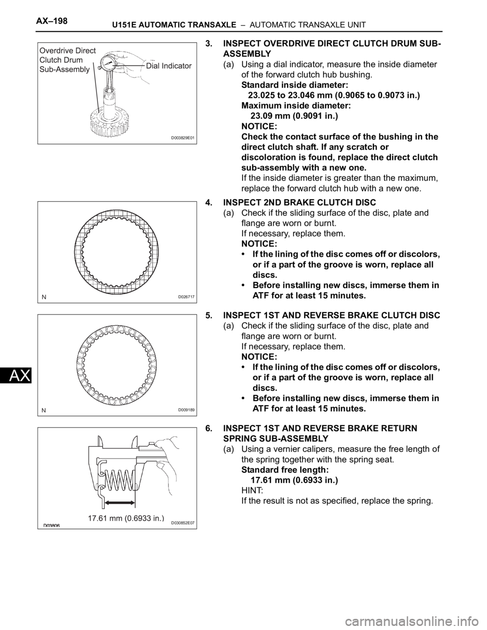
AX–198U151E AUTOMATIC TRANSAXLE – AUTOMATIC TRANSAXLE UNIT
AX
3. INSPECT OVERDRIVE DIRECT CLUTCH DRUM SUB-
ASSEMBLY
(a) Using a dial indicator, measure the inside diameter
of the forward clutch hub bushing.
Standard inside diameter:
23.025 to 23.046 mm (0.9065 to 0.9073 in.)
Maximum inside diameter:
23.09 mm (0.9091 in.)
NOTICE:
Check the contact surface of the bushing in the
direct clutch shaft. If any scratch or
discoloration is found, replace the direct clutch
sub-assembly with a new one.
If the inside diameter is greater than the maximum,
replace the forward clutch hub with a new one.
4. INSPECT 2ND BRAKE CLUTCH DISC
(a) Check if the sliding surface of the disc, plate and
flange are worn or burnt.
If necessary, replace them.
NOTICE:
• If the lining of the disc comes off or discolors,
or if a part of the groove is worn, replace all
discs.
• Before installing new discs, immerse them in
ATF for at least 15 minutes.
5. INSPECT 1ST AND REVERSE BRAKE CLUTCH DISC
(a) Check if the sliding surface of the disc, plate and
flange are worn or burnt.
If necessary, replace them.
NOTICE:
• If the lining of the disc comes off or discolors,
or if a part of the groove is worn, replace all
discs.
• Before installing new discs, immerse them in
ATF for at least 15 minutes.
6. INSPECT 1ST AND REVERSE BRAKE RETURN
SPRING SUB-ASSEMBLY
(a) Using a vernier calipers, measure the free length of
the spring together with the spring seat.
Standard free length:
17.61 mm (0.6933 in.)
HINT:
If the result is not as specified, replace the spring.
D003829E01
D026717
D009189
D030852E07