Page 1969 of 3000
AX–284U151F AUTOMATIC TRANSAXLE – DIFFERENTIAL CASE
AX
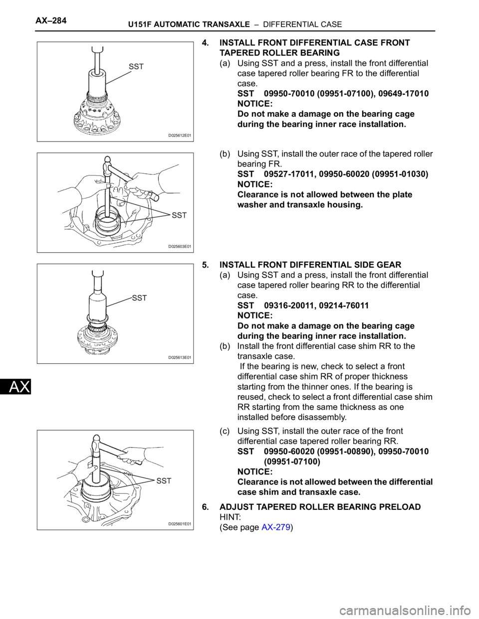
4. INSTALL FRONT DIFFERENTIAL CASE FRONT
TAPERED ROLLER BEARING
(a) Using SST and a press, install the front differential
case tapered roller bearing FR to the differential
case.
SST 09950-70010 (09951-07100), 09649-17010
NOTICE:
Do not make a damage on the bearing cage
during the bearing inner race installation.
(b) Using SST, install the outer race of the tapered roller
bearing FR.
SST 09527-17011, 09950-60020 (09951-01030)
NOTICE:
Clearance is not allowed between the plate
washer and transaxle housing.
5. INSTALL FRONT DIFFERENTIAL SIDE GEAR
(a) Using SST and a press, install the front differential
case tapered roller bearing RR to the differential
case.
SST 09316-20011, 09214-76011
NOTICE:
Do not make a damage on the bearing cage
during the bearing inner race installation.
(b) Install the front differential case shim RR to the
transaxle case.
If the bearing is new, check to select a front
differential case shim RR of proper thickness
starting from the thinner ones. If the bearing is
reused, check to select a front differential case shim
RR starting from the same thickness as one
installed before disassembly.
(c) Using SST, install the outer race of the front
differential case tapered roller bearing RR.
SST 09950-60020 (09951-00890), 09950-70010
(09951-07100)
NOTICE:
Clearance is not allowed between the differential
case shim and transaxle case.
6. ADJUST TAPERED ROLLER BEARING PRELOAD
HINT:
(See page AX-279)
D025612E01
D025603E01
D025613E01
D025601E01
Page 1970 of 3000
U151F AUTOMATIC TRANSAXLE – DIFFERENTIAL CASEAX–285
AX
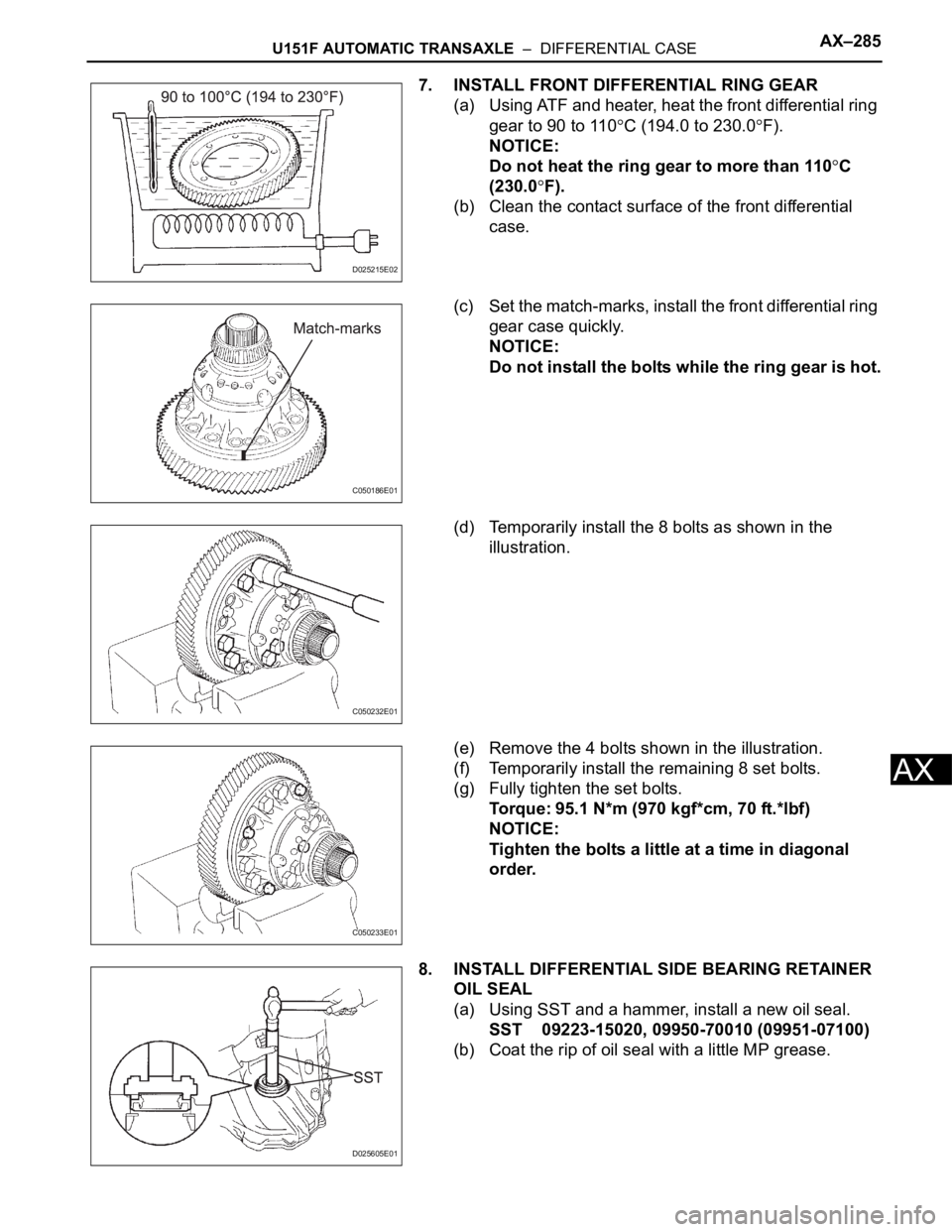
7. INSTALL FRONT DIFFERENTIAL RING GEAR
(a) Using ATF and heater, heat the front differential ring
gear to 90 to 110
C (194.0 to 230.0F).
NOTICE:
Do not heat the ring gear to more than 110
C
(230.0
F).
(b) Clean the contact surface of the front differential
case.
(c) Set the match-marks, install the front differential ring
gear case quickly.
NOTICE:
Do not install the bolts while the ring gear is hot.
(d) Temporarily install the 8 bolts as shown in the
illustration.
(e) Remove the 4 bolts shown in the illustration.
(f) Temporarily install the remaining 8 set bolts.
(g) Fully tighten the set bolts.
Torque: 95.1 N*m (970 kgf*cm, 70 ft.*lbf)
NOTICE:
Tighten the bolts a little at a time in diagonal
order.
8. INSTALL DIFFERENTIAL SIDE BEARING RETAINER
OIL SEAL
(a) Using SST and a hammer, install a new oil seal.
SST 09223-15020, 09950-70010 (09951-07100)
(b) Coat the rip of oil seal with a little MP grease.
D025215E02
C050186E01
C050232E01
C050233E01
D025605E01
Page 1971 of 3000
AX–286U151F AUTOMATIC TRANSAXLE – DIFFERENTIAL CASE
AX
9. INSTALL TRANSAXLE HOUSING OIL SEAL
(a) Wind a vinyl tape around SST at the place 6.0 mm
(0.236 in.) above from the bottom end until the
thickness of the wound tape is about 5.0 mm (0.197
in.).
SST 09950-60020 (09951-00730)
NOTICE:
Remove foreign matter such as grease on the
SST before winding the tape.
(b) Coat the rip of oil seal with a little MP grease.
(c) Using SST, install a new oil seal.
SST 09950-60020 (09951-00730), 09950-70010
(09951-07150)
Standard press in depth:
5.5 - 6.5 mm (0.217 - 0.256 in.)
NOTICE:
Stop pressing when the would vinyl tape is
contact with the transaxle housing.
D003809E02
D025615E01
Page 1981 of 3000
U151F AUTOMATIC TRANSAXLE – UNDERDRIVE PLANETARY GEARAX–259
AX
DISASSEMBLY
1. INSPECT UNDERDRIVE PLANETARY GEAR
PRELOAD
HINT:
(See page AX-260)
2. REMOVE FRONT PLANETARY GEAR NUT
(a) Using SST, loosen the staked part of the lock nut.
SST 09930-00010 (09931-00010, 09931-00020),
09387-00050
(b) Place the underdrive planetary gear in a soft jaw
vise.
NOTICE:
Be careful not to damage the differential drive
pinion.
(c) Using a socket wrench, remove the lock nut.
3. REMOVE CYLINDRICAL ROLLER BEARING RACE
INNER
(a) Using SST, remove the cylindrical roller bearing
race inner.
SST 09950-00020, 09950-00030, 09950-60010
(09951-00320, 09957-04010)
D003686E01
D003687E02
D025609E02
D003689E01
Page 1982 of 3000
AX–260U151F AUTOMATIC TRANSAXLE – UNDERDRIVE PLANETARY GEAR
AX
4. REMOVE UNDERDRIVE PLANETARY GEAR
ASSEMBLY
(a) Using SST and a press, remove the differential drive
pinion, parking lock gear, counter driven gear with
underdrive planetary ring gear and radial ball
bearing front.
SST 09950-60010 (09951-00320), 09387-00050,
09950-00020, 09950-00030, 09950-40011
(09957-04010)
(b) Place the underdrive planetary gear in a soft jaw
vise.
(c) Using SST, remove the radial ball bearing rear from
the underdrive planetary gear.
SST 09950-60010 (09951-00320), 09950-00030,
09950-40011 (09957-04010)
5. REMOVE UNDERDRIVE PLANETARY RING GEAR
(a) Using a snap ring pliers, remove the snap ring.
(b) Remove the underdrive planetary ring gear from the
counter driven gear.
INSPECTION
1. INSPECT UNDERDRIVE PLANETARY GEAR
PRELOAD
(a) Using SST, fix the underdrive planetary gear
assembly.
SST 09387-00050
D026437E01
D003691E01
D003826E01
D003827E02
D025593E01
Page 1985 of 3000
U151F AUTOMATIC TRANSAXLE – UNDERDRIVE PLANETARY GEARAX–263
AX
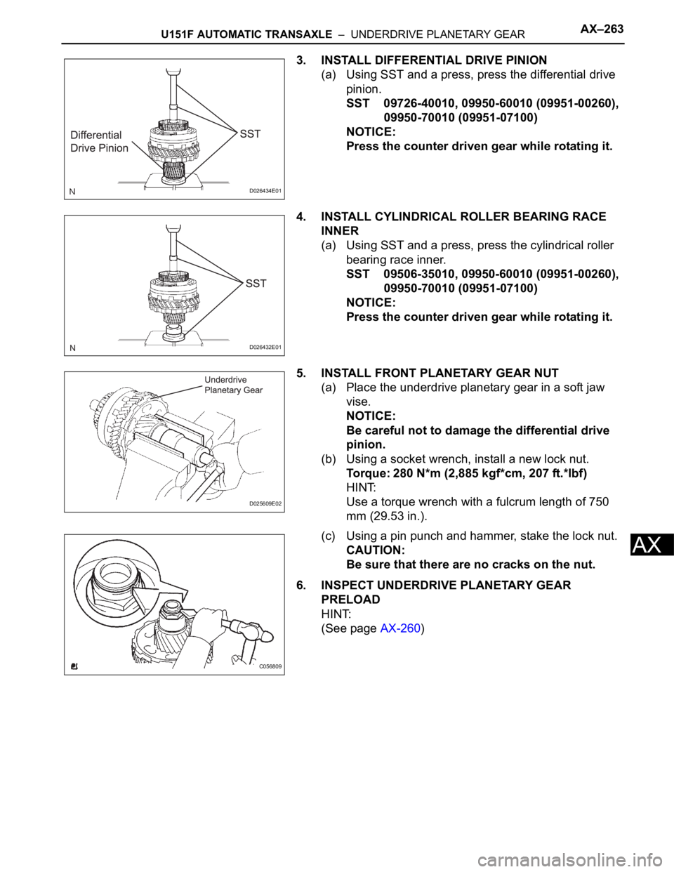
3. INSTALL DIFFERENTIAL DRIVE PINION
(a) Using SST and a press, press the differential drive
pinion.
SST 09726-40010, 09950-60010 (09951-00260),
09950-70010 (09951-07100)
NOTICE:
Press the counter driven gear while rotating it.
4. INSTALL CYLINDRICAL ROLLER BEARING RACE
INNER
(a) Using SST and a press, press the cylindrical roller
bearing race inner.
SST 09506-35010, 09950-60010 (09951-00260),
09950-70010 (09951-07100)
NOTICE:
Press the counter driven gear while rotating it.
5. INSTALL FRONT PLANETARY GEAR NUT
(a) Place the underdrive planetary gear in a soft jaw
vise.
NOTICE:
Be careful not to damage the differential drive
pinion.
(b) Using a socket wrench, install a new lock nut.
Torque: 280 N*m (2,885 kgf*cm, 207 ft.*lbf)
HINT:
Use a torque wrench with a fulcrum length of 750
mm (29.53 in.).
(c) Using a pin punch and hammer, stake the lock nut.
CAUTION:
Be sure that there are no cracks on the nut.
6. INSPECT UNDERDRIVE PLANETARY GEAR
PRELOAD
HINT:
(See page AX-260)
D026434E01
D026432E01
D025609E02
C056809
Page 1992 of 3000
AX–276U151F AUTOMATIC TRANSAXLE – DIFFERENTIAL CASE
AX
INSPECTION
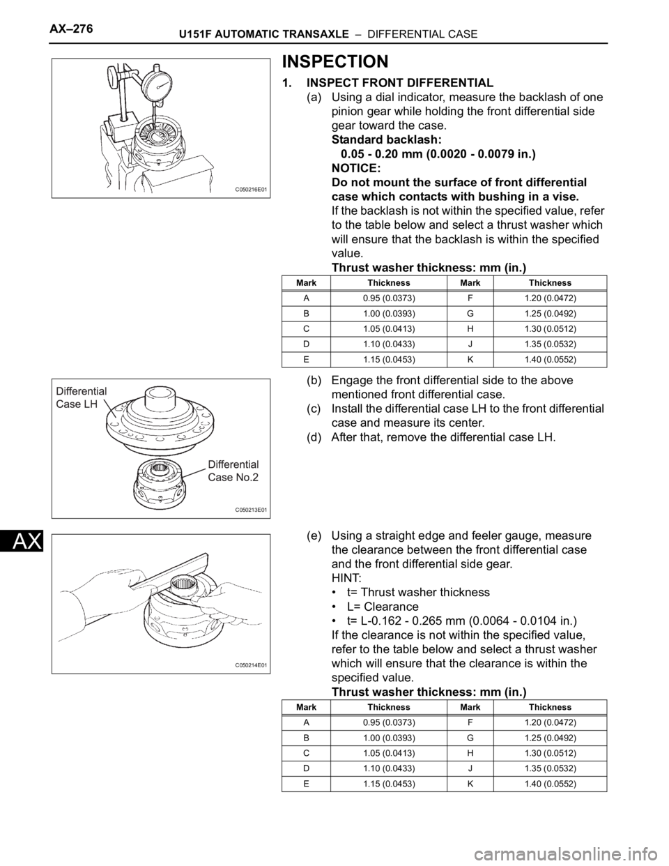
1. INSPECT FRONT DIFFERENTIAL
(a) Using a dial indicator, measure the backlash of one
pinion gear while holding the front differential side
gear toward the case.
Standard backlash:
0.05 - 0.20 mm (0.0020 - 0.0079 in.)
NOTICE:
Do not mount the surface of front differential
case which contacts with bushing in a vise.
If the backlash is not within the specified value, refer
to the table below and select a thrust washer which
will ensure that the backlash is within the specified
value.
Thrust washer thickness: mm (in.)
(b) Engage the front differential side to the above
mentioned front differential case.
(c) Install the differential case LH to the front differential
case and measure its center.
(d) After that, remove the differential case LH.
(e) Using a straight edge and feeler gauge, measure
the clearance between the front differential case
and the front differential side gear.
HINT:
• t= Thrust washer thickness
• L= Clearance
• t= L-0.162 - 0.265 mm (0.0064 - 0.0104 in.)
If the clearance is not within the specified value,
refer to the table below and select a thrust washer
which will ensure that the clearance is within the
specified value.
Thrust washer thickness: mm (in.)
C050216E01
Mark Thickness Mark Thickness
A 0.95 (0.0373) F 1.20 (0.0472)
B 1.00 (0.0393) G 1.25 (0.0492)
C 1.05 (0.0413) H 1.30 (0.0512)
D 1.10 (0.0433) J 1.35 (0.0532)
E 1.15 (0.0453) K 1.40 (0.0552)
C050213E01
C050214E01
Mark Thickness Mark Thickness
A 0.95 (0.0373) F 1.20 (0.0472)
B 1.00 (0.0393) G 1.25 (0.0492)
C 1.05 (0.0413) H 1.30 (0.0512)
D 1.10 (0.0433) J 1.35 (0.0532)
E 1.15 (0.0453) K 1.40 (0.0552)
Page 1993 of 3000
U151F AUTOMATIC TRANSAXLE – DIFFERENTIAL CASEAX–277
AX
If the clearance is not within the specified value,
parts may have been assembled incorrectly, so
check and reassemble it.
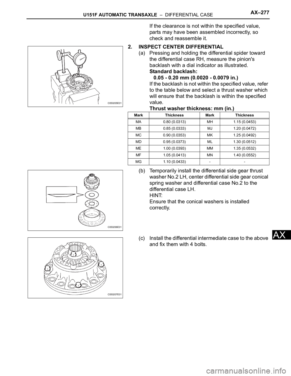
2. INSPECT CENTER DIFFERENTIAL
(a) Pressing and holding the differential spider toward
the differential case RH, measure the pinion's
backlash with a dial indicator as illustrated.
Standard backlash:
0.05 - 0.20 mm (0.0020 - 0.0079 in.)
If the backlash is not within the specified value, refer
to the table below and select a thrust washer which
will ensure that the backlash is within the specified
value.
Thrust washer thickness: mm (in.)
(b) Temporarily install the differential side gear thrust
washer No.2 LH, center differential side gear conical
spring washer and differential case No.2 to the
differential case LH.
HINT:
Ensure that the conical washers is installed
correctly.
(c) Install the differential intermediate case to the above
and fix them with 4 bolts.
C050205E01
Mark Thickness Mark Thickness
MA 0.80 (0.0313) MH 1.15 (0.0453)
MB 0.85 (0.0333) MJ 1.20 (0.0472)
MC 0.90 (0.0353) MK 1.25 (0.0492)
MD 0.95 (0.0373) ML 1.30 (0.0512)
ME 1.00 (0.0393) MM 1.35 (0.0532)
MF 1.05 (0.0413) MN 1.40 (0.0552)
MG 1.10 (0.0433) - -
C050206E01
C050207E01