Page 1684 of 3000
AX–274U151E AUTOMATIC TRANSAXLE – DIFFERENTIAL CASE
AX
10. INSTALL DIFFERENTIAL SIDE BEARING RETAINER
OIL SEAL
(a) Using SST and a hammer, install a new oil seal.
SST 09710-30050, 09950-70010 (09951-07150)
(b) Coat the lip of the oil seal with a little MP grease.
Oil seal installation depth:
0 +- 0.5 mm (0 +- 0.0197 in.)
D025606E01
Page 1693 of 3000
AX–10U151F AUTOMATIC TRANSAXLE – AUTOMATIC TRANSAXLE SYSTEM
AX
ROAD TEST
1. PROBLEM SYMPTOM CONFIRMATION
(a) Based on the result of the customer problem
analysis, try to reproduce the symptoms. If the
problem is that the transaxle does not shift up, shift
down, or the shift point is too high or too low,
conduct the following road test referring to the
automatic shift schedule and simulate the problem
symptoms.
2. ROAD TEST
NOTICE:
Perform the test at the ATF temperature 50 to 80
C
(122 to 176
F) in the normal operation.
(a) D position test:
Shift into the D position and fully depress the
accelerator pedal and check the following points.
(1) Check up-shift operation.
Check that 1
2, 2 3, 3 4 and 4 5th up-
shifts take place, and that the shift points
conform to the automatic shift schedule (See
page SS-31).
HINT:
5th Gear Up-shift Prohibition Control
• Engine coolant temperature is 55
C (131F)
or less and vehicle speed is at 80 km/h (176
mph) or less.
• ATF temperature is -2
C (28F) or less.
4th Gear Up-shift Prohibition Control
• Coolant temperature is 47
C (117F) or less
and vehicle speed is at 55 km/h (34 mph) or
less.
5th and 4th Gear Lock-up Prohibition Control
• Brake pedal is depressed.
• Accelerator pedal is released.
• Coolant temperature is 60
C (140F) or less.
(2) Check for shift shock and slip.
Check for shock and slip at the 1
2, 2 3, 3
4 and 4 5th up-shifts.
(3) Check for abnormal noise and vibration.
Drive in the D position lock-up or 5th gear, and
check for abnormal noises and vibration.
HINT:
The check for the cause of abnormal noise and
vibration must be done very thoroughly as it
could also be due to loss of balance in the
differential, torque converter clutch, etc.
(4) Check kick-down operation.
Check that the possible kick-down vehicle speed
limits for 2nd to 1st, 3rd to 2nd, 4th to 3rd, 5th to
4th kick-downs conform to those indicated on
the automatic shift schedule while driving
through all gears with the shift lever in the D
position (See page SS-31).
(5) Check abnormal shock and slip at kick-down.
Page 1802 of 3000
AX–10U151F AUTOMATIC TRANSAXLE – AUTOMATIC TRANSAXLE SYSTEM
AX
ROAD TEST
1. PROBLEM SYMPTOM CONFIRMATION
(a) Based on the result of the customer problem
analysis, try to reproduce the symptoms. If the
problem is that the transaxle does not shift up, shift
down, or the shift point is too high or too low,
conduct the following road test referring to the
automatic shift schedule and simulate the problem
symptoms.
2. ROAD TEST
NOTICE:
Perform the test at the ATF temperature 50 to 80
C
(122 to 176
F) in the normal operation.
(a) D position test:
Shift into the D position and fully depress the
accelerator pedal and check the following points.
(1) Check up-shift operation.
Check that 1
2, 2 3, 3 4 and 4 5th up-
shifts take place, and that the shift points
conform to the automatic shift schedule (See
page SS-31).
HINT:
5th Gear Up-shift Prohibition Control
• Engine coolant temperature is 55
C (131F)
or less and vehicle speed is at 80 km/h (176
mph) or less.
• ATF temperature is -2
C (28F) or less.
4th Gear Up-shift Prohibition Control
• Coolant temperature is 47
C (117F) or less
and vehicle speed is at 55 km/h (34 mph) or
less.
5th and 4th Gear Lock-up Prohibition Control
• Brake pedal is depressed.
• Accelerator pedal is released.
• Coolant temperature is 60
C (140F) or less.
(2) Check for shift shock and slip.
Check for shock and slip at the 1
2, 2 3, 3
4 and 4 5th up-shifts.
(3) Check for abnormal noise and vibration.
Drive in the D position lock-up or 5th gear, and
check for abnormal noises and vibration.
HINT:
The check for the cause of abnormal noise and
vibration must be done very thoroughly as it
could also be due to loss of balance in the
differential, torque converter clutch, etc.
(4) Check kick-down operation.
Check that the possible kick-down vehicle speed
limits for 2nd to 1st, 3rd to 2nd, 4th to 3rd, 5th to
4th kick-downs conform to those indicated on
the automatic shift schedule while driving
through all gears with the shift lever in the D
position (See page SS-31).
(5) Check abnormal shock and slip at kick-down.
Page 1863 of 3000
AX–188U151F AUTOMATIC TRANSAXLE – AUTOMATIC TRANSAXLE UNIT
AX
28. INSPECT INPUT SHAFT ENDPLAY
HINT:
(See page AX-204)
29. REMOVE TRANSAXLE HOUSING
(a) Remove the 16 bolts.
(b) Tap on the circumference of the transaxle housing
with a plastic hammer to remove the transaxle
housing from the transaxle case.
NOTICE:
The differential may be accidentally removed
when the transaxle housing is removed.
30. REMOVE OIL PUMP ASSEMBLY
(a) Remove the 7 bolts and oil pump from the transaxle
case.
31. REMOVE THRUST NEEDLE ROLLER BEARING
(a) Remove the thrust needle roller bearing from the
underdrive planetary gear assembly.
32. REMOVE THRUST BEARING UNDERDRIVE RACE
NO.2
(a) Remove the thrust bearing underdrive race No.2
from the underdrive planetary gear assembly.
D003568
D003569E05
D025505E02
D025506E03
Page 1864 of 3000
U151F AUTOMATIC TRANSAXLE – AUTOMATIC TRANSAXLE UNITAX–189
AX
33. REMOVE DIFFERENTIAL GEAR ASSEMBLY
(a) Remove the differential gear assembly from the
transaxle case.
34. REMOVE OVERDRIVE BRAKE GASKET
(a) Remove the 2 overdrive brake gaskets from the
transaxle case.
35. REMOVE FORWARD CLUTCH ASSEMBLY
(a) Remove the forward clutch assembly from the
transaxle case.
(b) Remove the thrust needle roller bearing from the
forward clutch.
36. REMOVE MULTIPLE DISC CLUTCH HUB
(a) Remove the thrust needle roller bearing, multiple
disc clutch hub, thrust needle roller bearing and
thrust bearing race No.1 from the transaxle case.
37. INSPECT MULTIPLE DISC CLUTCH CLUTCH HUB
HINT:
(See page AX-201)
D026450E04
D003573
D003574E02
D003906E01
D026787E03
Page 1876 of 3000
U151F AUTOMATIC TRANSAXLE – AUTOMATIC TRANSAXLE UNITAX–201
AX
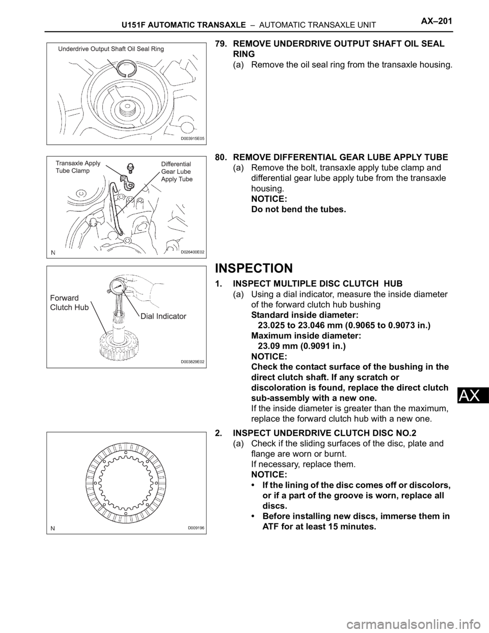
79. REMOVE UNDERDRIVE OUTPUT SHAFT OIL SEAL
RING
(a) Remove the oil seal ring from the transaxle housing.
80. REMOVE DIFFERENTIAL GEAR LUBE APPLY TUBE
(a) Remove the bolt, transaxle apply tube clamp and
differential gear lube apply tube from the transaxle
housing.
NOTICE:
Do not bend the tubes.
INSPECTION
1. INSPECT MULTIPLE DISC CLUTCH HUB
(a) Using a dial indicator, measure the inside diameter
of the forward clutch hub bushing
Standard inside diameter:
23.025 to 23.046 mm (0.9065 to 0.9073 in.)
Maximum inside diameter:
23.09 mm (0.9091 in.)
NOTICE:
Check the contact surface of the bushing in the
direct clutch shaft. If any scratch or
discoloration is found, replace the direct clutch
sub-assembly with a new one.
If the inside diameter is greater than the maximum,
replace the forward clutch hub with a new one.
2. INSPECT UNDERDRIVE CLUTCH DISC NO.2
(a) Check if the sliding surfaces of the disc, plate and
flange are worn or burnt.
If necessary, replace them.
NOTICE:
• If the lining of the disc comes off or discolors,
or if a part of the groove is worn, replace all
discs.
• Before installing new discs, immerse them in
ATF for at least 15 minutes.
D003915E05
D026400E02
D003829E02
D009196
Page 1889 of 3000
AX–206U151F AUTOMATIC TRANSAXLE – AUTOMATIC TRANSAXLE UNIT
AX
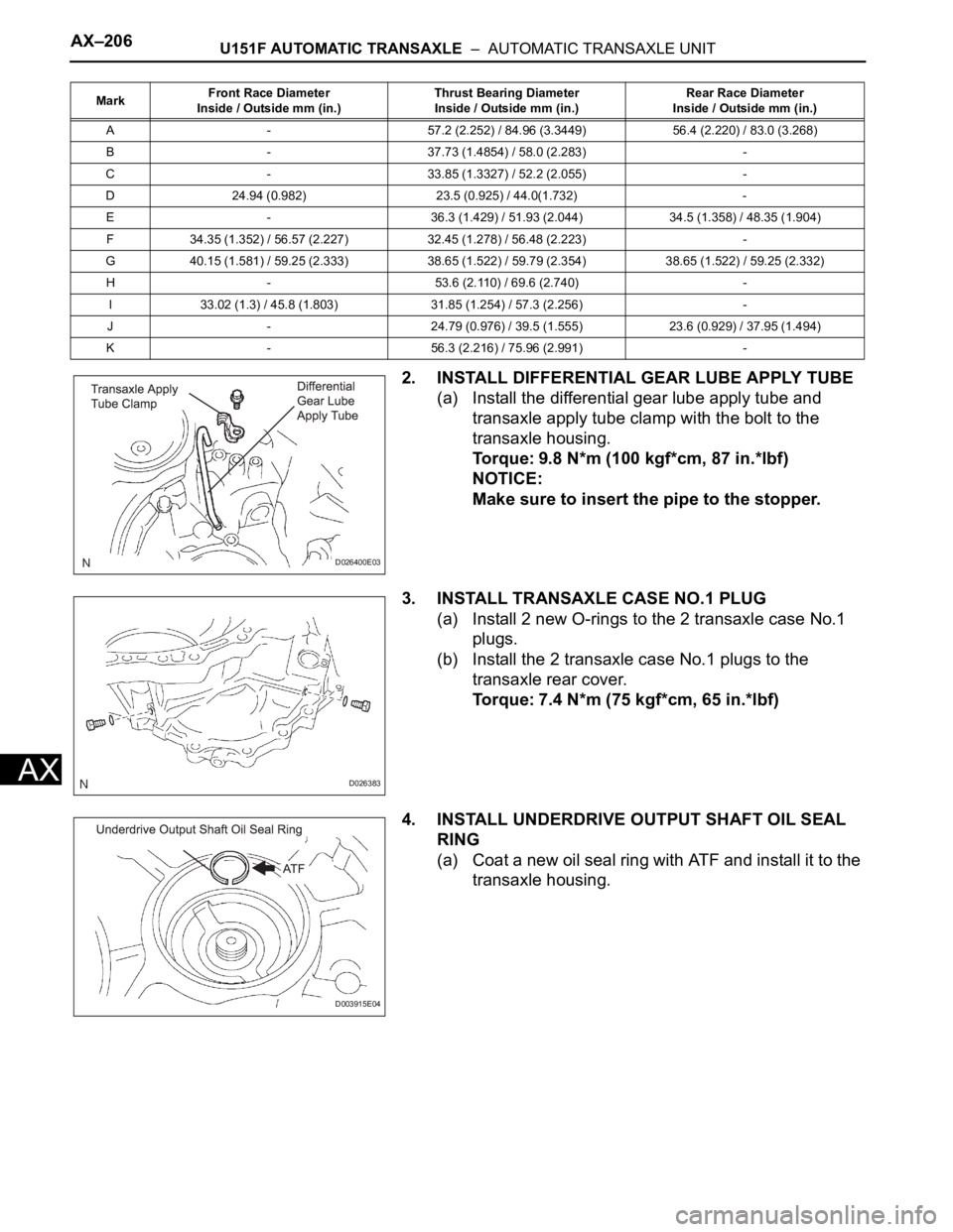
2. INSTALL DIFFERENTIAL GEAR LUBE APPLY TUBE
(a) Install the differential gear lube apply tube and
transaxle apply tube clamp with the bolt to the
transaxle housing.
Torque: 9.8 N*m (100 kgf*cm, 87 in.*lbf)
NOTICE:
Make sure to insert the pipe to the stopper.
3. INSTALL TRANSAXLE CASE NO.1 PLUG
(a) Install 2 new O-rings to the 2 transaxle case No.1
plugs.
(b) Install the 2 transaxle case No.1 plugs to the
transaxle rear cover.
Torque: 7.4 N*m (75 kgf*cm, 65 in.*lbf)
4. INSTALL UNDERDRIVE OUTPUT SHAFT OIL SEAL
RING
(a) Coat a new oil seal ring with ATF and install it to the
transaxle housing.
MarkFront Race Diameter
Inside / Outside mm (in.)Thrust Bearing Diameter
Inside / Outside mm (in.)Rear Race Diameter
Inside / Outside mm (in.)
A - 57.2 (2.252) / 84.96 (3.3449) 56.4 (2.220) / 83.0 (3.268)
B - 37.73 (1.4854) / 58.0 (2.283) -
C - 33.85 (1.3327) / 52.2 (2.055) -
D 24.94 (0.982) 23.5 (0.925) / 44.0(1.732) -
E - 36.3 (1.429) / 51.93 (2.044) 34.5 (1.358) / 48.35 (1.904)
F 34.35 (1.352) / 56.57 (2.227) 32.45 (1.278) / 56.48 (2.223) -
G 40.15 (1.581) / 59.25 (2.333) 38.65 (1.522) / 59.79 (2.354) 38.65 (1.522) / 59.25 (2.332)
H - 53.6 (2.110) / 69.6 (2.740) -
I 33.02 (1.3) / 45.8 (1.803) 31.85 (1.254) / 57.3 (2.256) -
J - 24.79 (0.976) / 39.5 (1.555) 23.6 (0.929) / 37.95 (1.494)
K - 56.3 (2.216) / 75.96 (2.991) -
D026400E03
D026383
D003915E04
Page 1906 of 3000
U151F AUTOMATIC TRANSAXLE – AUTOMATIC TRANSAXLE UNITAX–223
AX
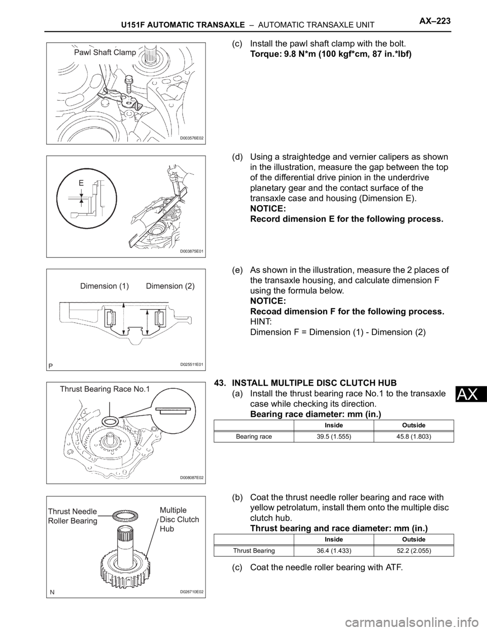
(c) Install the pawl shaft clamp with the bolt.
Torque: 9.8 N*m (100 kgf*cm, 87 in.*lbf)
(d) Using a straightedge and vernier calipers as shown
in the illustration, measure the gap between the top
of the differential drive pinion in the underdrive
planetary gear and the contact surface of the
transaxle case and housing (Dimension E).
NOTICE:
Record dimension E for the following process.
(e) As shown in the illustration, measure the 2 places of
the transaxle housing, and calculate dimension F
using the formula below.
NOTICE:
Recoad dimension F for the following process.
HINT:
Dimension F = Dimension (1) - Dimension (2)
43. INSTALL MULTIPLE DISC CLUTCH HUB
(a) Install the thrust bearing race No.1 to the transaxle
case while checking its direction.
Bearing race diameter: mm (in.)
(b) Coat the thrust needle roller bearing and race with
yellow petrolatum, install them onto the multiple disc
clutch hub.
Thrust bearing and race diameter: mm (in.)
(c) Coat the needle roller bearing with ATF.
D003576E02
D003875E01
D025511E01
D008087E02
Inside Outside
Bearing race 39.5 (1.555) 45.8 (1.803)
D026710E02
Inside Outside
Thrust Bearing 36.4 (1.433) 52.2 (2.055)