Page 2025 of 3000
TRANSFER – TRANSFER UNITTF–35
TF
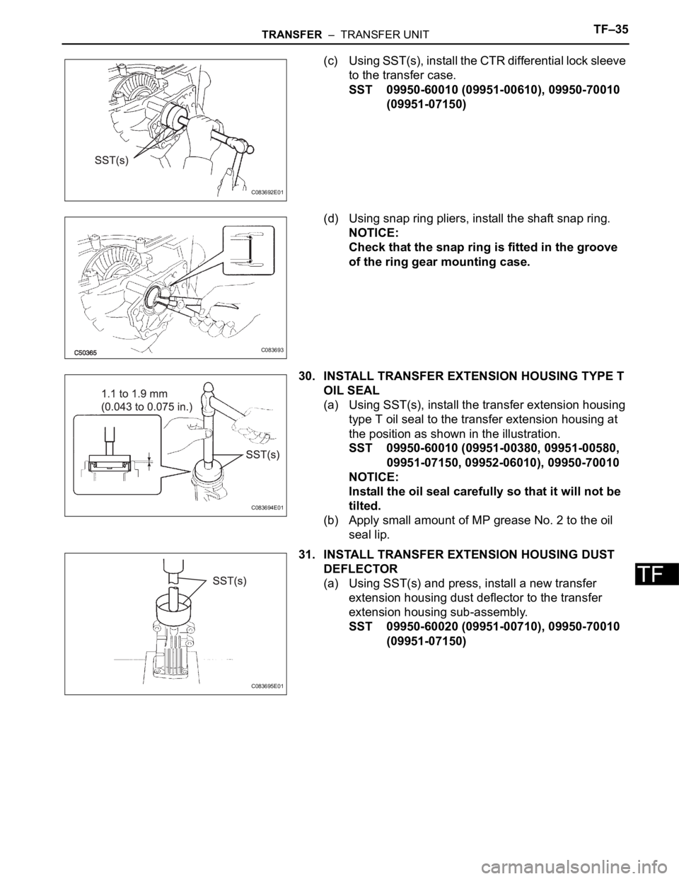
(c) Using SST(s), install the CTR differential lock sleeve
to the transfer case.
SST 09950-60010 (09951-00610), 09950-70010
(09951-07150)
(d) Using snap ring pliers, install the shaft snap ring.
NOTICE:
Check that the snap ring is fitted in the groove
of the ring gear mounting case.
30. INSTALL TRANSFER EXTENSION HOUSING TYPE T
OIL SEAL
(a) Using SST(s), install the transfer extension housing
type T oil seal to the transfer extension housing at
the position as shown in the illustration.
SST 09950-60010 (09951-00380, 09951-00580,
09951-07150, 09952-06010), 09950-70010
NOTICE:
Install the oil seal carefully so that it will not be
tilted.
(b) Apply small amount of MP grease No. 2 to the oil
seal lip.
31. INSTALL TRANSFER EXTENSION HOUSING DUST
DEFLECTOR
(a) Using SST(s) and press, install a new transfer
extension housing dust deflector to the transfer
extension housing sub-assembly.
SST 09950-60020 (09951-00710), 09950-70010
(09951-07150)
C083692E01
C083693
C083694E01
C083695E01
Page 2038 of 3000
TRANSFER – TRANSFER UNITTF–15
TF
(b) Using a plastic hammer, remove the transfer
extension housing sub- assembly from the transfer
case.
12. INSPECT PRELOAD
(a) Using SST(s) and a torque wrench, check the initial
torque with the backlash range.
SST 09326-20011
Torque: 0.9 to 1.4 N*m (9 to 14 kgf*cm, 8.0 to
12.4 in.*lbf)
HINT:
Use a torque wrench with a fulcrum length of 160
mm (6.30 in.)
(b) Using SST(s) and a torque wrench, check the initial
torque while the driven pinion is in contact with the
ring gear face.
SST 09326-20011
Torque: Preload
+ 0.15 to 0.30 N*m (+ 1.6 to 3.1 kgf*cm, +
1.3 to 2.7 in.*lbf)
HINT:
Use a torque wrench with a fulcrum length of 160
mm (6.30 in.)
13. REMOVE CTR DIFFERENTIAL LOCK SLEEVE
(a) Using snap ring pliers, remove the shaft snap ring.
(b) Using SST(s), remove the CTR differential lock
sleeve.
SST 09308-00010
C082791
C083635E01
C083637
C083638E01
Page 2039 of 3000
TF–16TRANSFER – TRANSFER UNIT
TF
14. REMOVE O-RING
(a) Using a screwdriver with the tip protected by vinyl
tape, remove the O-ring from the CTR differential
lock sleeve.
NOTICE:
Be careful not to damage the lock sleeve's
groove for the O-ring.
15. REMOVE TRANSFER CASE OIL SEAL
(a) Using SST(s), remove the transfer case oil seal
from the case.
SST 09308-00010
NOTICE:
Be careful not to damage the oil-seal-fitted
surface of the case.
16. REMOVE TRANSFER RH BEARING RETAINER OIL
SEAL
(a) Using SST(s), remove the transfer RH bearing
retainer oil seal from the transfer RH bearing
retainer sub-assembly.
SST 09308-00010
NOTICE:
Be careful not to damage the oil-seal-fitted
surface of the retainer.
17. REMOVE TRANSFER RH BEARING RETAINER SUB-
ASSEMBLY
(a) Remove the 7 bolts from the transfer RH bearing
retainer sub-assembly.
C050311
C083630E02
C082980E01
C083509
Page 2040 of 3000
TRANSFER – TRANSFER UNITTF–17
TF
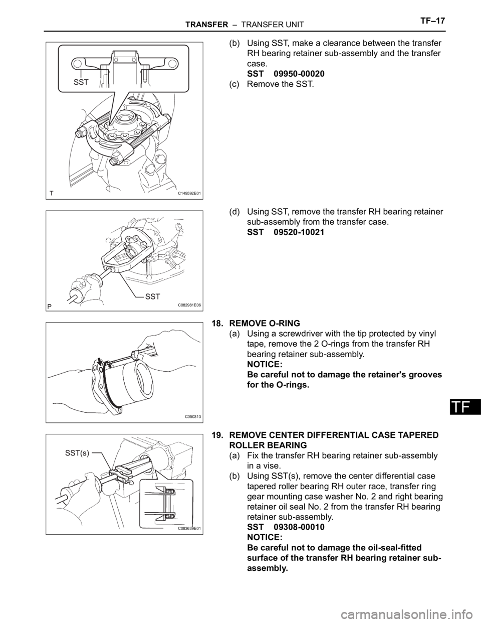
(b) Using SST, make a clearance between the transfer
RH bearing retainer sub-assembly and the transfer
case.
SST 09950-00020
(c) Remove the SST.
(d) Using SST, remove the transfer RH bearing retainer
sub-assembly from the transfer case.
SST 09520-10021
18. REMOVE O-RING
(a) Using a screwdriver with the tip protected by vinyl
tape, remove the 2 O-rings from the transfer RH
bearing retainer sub-assembly.
NOTICE:
Be careful not to damage the retainer's grooves
for the O-rings.
19. REMOVE CENTER DIFFERENTIAL CASE TAPERED
ROLLER BEARING
(a) Fix the transfer RH bearing retainer sub-assembly
in a vise.
(b) Using SST(s), remove the center differential case
tapered roller bearing RH outer race, transfer ring
gear mounting case washer No. 2 and right bearing
retainer oil seal No. 2 from the transfer RH bearing
retainer sub-assembly.
SST 09308-00010
NOTICE:
Be careful not to damage the oil-seal-fitted
surface of the transfer RH bearing retainer sub-
assembly.
C149592E01
C082981E06
C050313
C083639E01
Page 2041 of 3000
TF–18TRANSFER – TRANSFER UNIT
TF
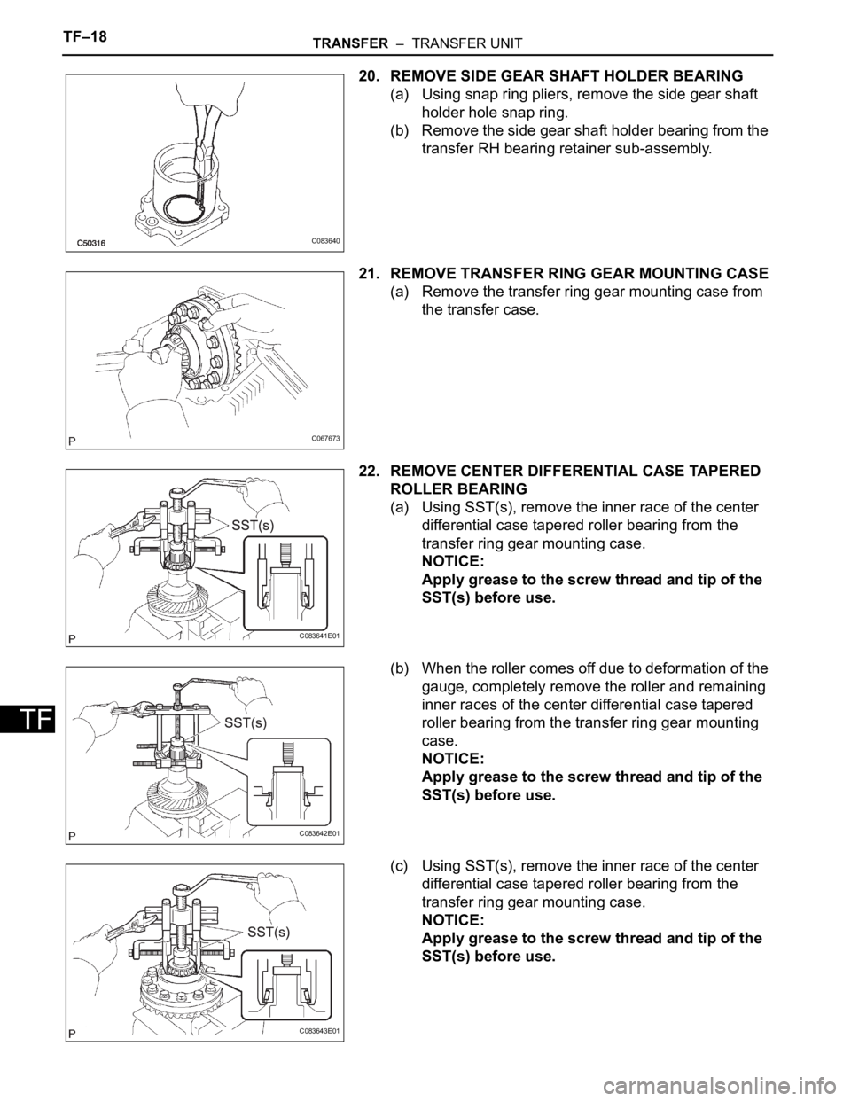
20. REMOVE SIDE GEAR SHAFT HOLDER BEARING
(a) Using snap ring pliers, remove the side gear shaft
holder hole snap ring.
(b) Remove the side gear shaft holder bearing from the
transfer RH bearing retainer sub-assembly.
21. REMOVE TRANSFER RING GEAR MOUNTING CASE
(a) Remove the transfer ring gear mounting case from
the transfer case.
22. REMOVE CENTER DIFFERENTIAL CASE TAPERED
ROLLER BEARING
(a) Using SST(s), remove the inner race of the center
differential case tapered roller bearing from the
transfer ring gear mounting case.
NOTICE:
Apply grease to the screw thread and tip of the
SST(s) before use.
(b) When the roller comes off due to deformation of the
gauge, completely remove the roller and remaining
inner races of the center differential case tapered
roller bearing from the transfer ring gear mounting
case.
NOTICE:
Apply grease to the screw thread and tip of the
SST(s) before use.
(c) Using SST(s), remove the inner race of the center
differential case tapered roller bearing from the
transfer ring gear mounting case.
NOTICE:
Apply grease to the screw thread and tip of the
SST(s) before use.
C083640
C067673
C083641E01
C083642E01
C083643E01
Page 2042 of 3000
TRANSFER – TRANSFER UNITTF–19
TF
(d) When the roller comes off due to deformation of the
gauge, completely remove the roller and remaining
inner races of the center differential case tapered
roller bearing from the transfer ring gear mounting
case.
NOTICE:
Apply grease to the screw thread and tip of the
SST(s) before use.
23. REMOVE RING GEAR
(a) Put matchmarks on the transfer ring gear mounting
case and the ring gear.
(b) Remove the 12 bolts.
(c) Using a plastic hammer, remove the ring gear by
tapping around its periphery.
NOTICE:
Do not damage the teeth of the ring gear.
24. REMOVE TRANSFER GEAR NUT
(a) Using SST(s) and a hammer, unstake the transfer
gear nut.
SST 09930-00010
(b) Using SST(s), remove the transfer gear nut.
C083644E01
C083645E01
C067677
C082795E01
C082984E01
Page 2043 of 3000
TF–20TRANSFER – TRANSFER UNIT
TF
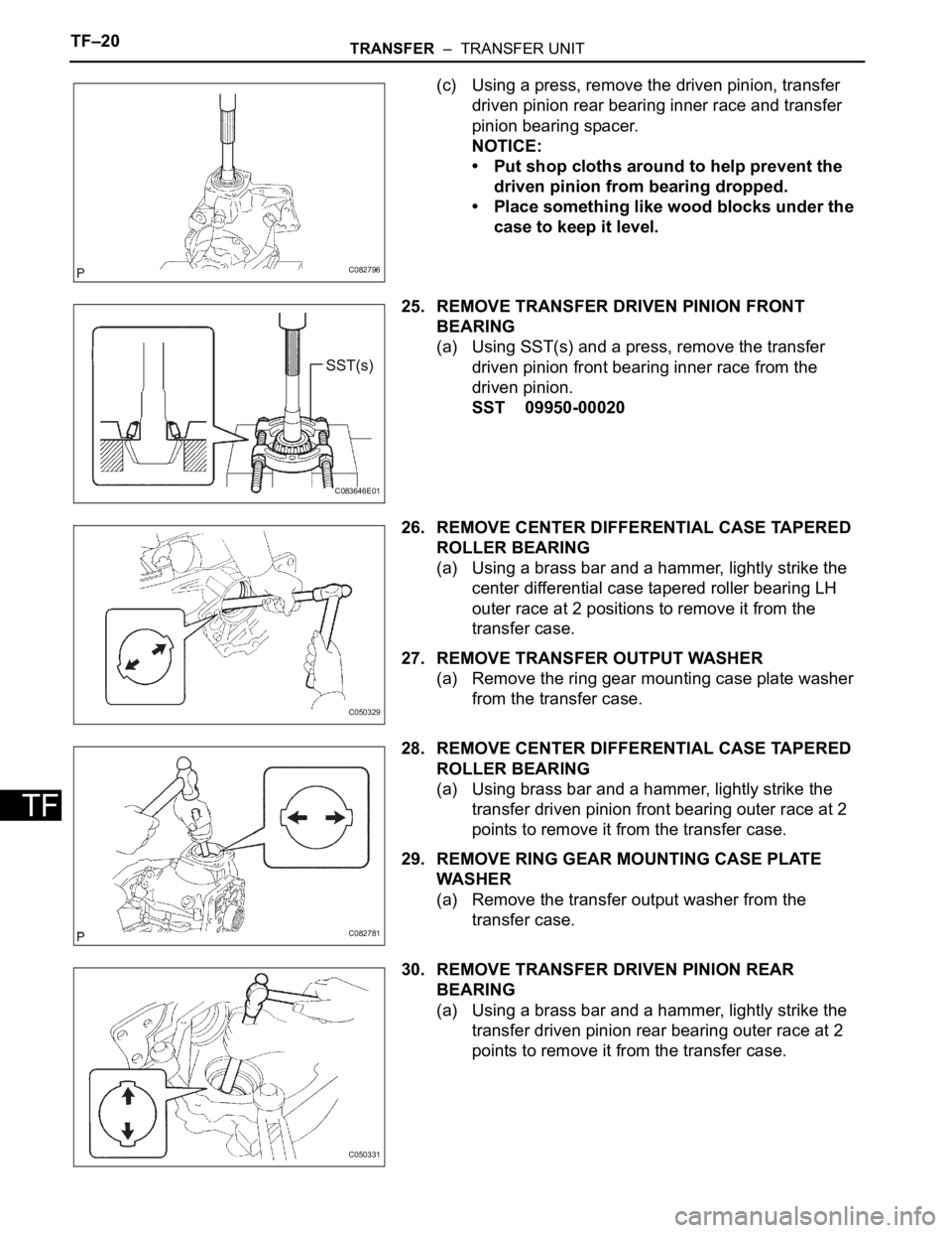
(c) Using a press, remove the driven pinion, transfer
driven pinion rear bearing inner race and transfer
pinion bearing spacer.
NOTICE:
• Put shop cloths around to help prevent the
driven pinion from bearing dropped.
• Place something like wood blocks under the
case to keep it level.
25. REMOVE TRANSFER DRIVEN PINION FRONT
BEARING
(a) Using SST(s) and a press, remove the transfer
driven pinion front bearing inner race from the
driven pinion.
SST 09950-00020
26. REMOVE CENTER DIFFERENTIAL CASE TAPERED
ROLLER BEARING
(a) Using a brass bar and a hammer, lightly strike the
center differential case tapered roller bearing LH
outer race at 2 positions to remove it from the
transfer case.
27. REMOVE TRANSFER OUTPUT WASHER
(a) Remove the ring gear mounting case plate washer
from the transfer case.
28. REMOVE CENTER DIFFERENTIAL CASE TAPERED
ROLLER BEARING
(a) Using brass bar and a hammer, lightly strike the
transfer driven pinion front bearing outer race at 2
points to remove it from the transfer case.
29. REMOVE RING GEAR MOUNTING CASE PLATE
WA S HE R
(a) Remove the transfer output washer from the
transfer case.
30. REMOVE TRANSFER DRIVEN PINION REAR
BEARING
(a) Using a brass bar and a hammer, lightly strike the
transfer driven pinion rear bearing outer race at 2
points to remove it from the transfer case.
C082796
C083646E01
C050329
C082781
C050331
Page 2044 of 3000
TRANSFER – TRANSFER UNITTF–21
TF
INSPECTION
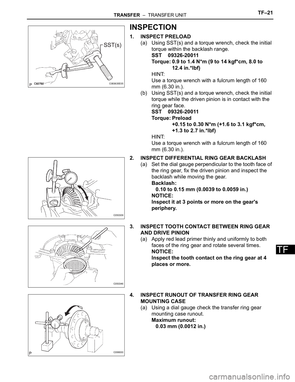
1. INSPECT PRELOAD
(a) Using SST(s) and a torque wrench, check the initial
torque within the backlash range.
SST 09326-20011
Torque: 0.9 to 1.4 N*m (9 to 14 kgf*cm, 8.0 to
12.4 in.*lbf)
HINT:
Use a torque wrench with a fulcrum length of 160
mm (6.30 in.).
(b) Using SST(s) and a torque wrench, check the initial
torque while the driven pinion is in contact with the
ring gear face.
SST 09326-20011
Torque: Preload
+0.15 to 0.30 N*m (+1.6 to 3.1 kgf*cm,
+1.3 to 2.7 in.*lbf)
HINT:
Use a torque wrench with a fulcrum length of 160
mm (6.30 in.).
2. INSPECT DIFFERENTIAL RING GEAR BACKLASH
(a) Set the dial gauge perpendicular to the tooth face of
the ring gear, fix the driven pinion and inspect the
backlash while moving the gear.
Backlash:
0.10 to 0.15 mm (0.0039 to 0.0059 in.)
NOTICE:
Inspect it at 3 points or more on the gear's
periphery.
3. INSPECT TOOTH CONTACT BETWEEN RING GEAR
AND DRIVE PINION
(a) Apply red lead primer thinly and uniformly to both
faces of the ring gear and rotate several times.
NOTICE:
Inspect the tooth contact on the ring gear at 4
places or more.
4. INSPECT RUNOUT OF TRANSFER RING GEAR
MOUNTING CASE
(a) Using a dial gauge check the transfer ring gear
mounting case runout.
Maximum runout:
0.03 mm (0.0012 in.)
C083635E05
C050309
C050346
C099000