Page 2104 of 3000
PREPARATION – DIFFERENTIALPP–49
PP
LUBRICANT
Item Capacity Classification
Differential oil 0.90 +- 0.05 liters (0.95 +- 0.05 US qts, 0.75
+- 0.04 lmp.qts)Hypoid gear oil API GL-5 Above -18
C (0F)
SAE 90 Below -18
C (0F) SAE 80W or 80W-
90
Page 2105 of 3000
PP–50PREPARATION – DIFFERENTIAL
PP
SSM
Toyota Genuine Seal Packing 1281,
Three Bond 1281 or equivalent
Page 2110 of 3000

DF–10DIFFERENTIAL – REAR DIFFERENTIAL CARRIER ASSEMBLY
DF
REMOVAL
1. REMOVE REAR WHEEL
2. REMOVE EXHAUST PIPE ASSEMBLY
HINT:
(See page EX-8)
3. REMOVE PROPELLER WITH CENTER BEARING
SHAFT ASSEMBLY
HINT:
(See page PR-3)
4. REMOVE REAR DIFFERENTIAL FILLER PLUG
(a) Using a hexagon wrench (10 mm), remove the filler
plug and gasket.
5. REMOVE REAR DIFFERENTIAL DRAIN PLUG
(a) Using a hexagon wrench (10 mm), remove the drain
plug and gasket, and drain the oil.
6. REMOVE REAR SPEED SENSOR LH
HINT:
Removal procedure or RH side is the same as that or LH
side. (See page DS-21)
7. REMOVE REAR AXLE SHAFT NUT LH
HINT:
Removal procedure or RH side is the same as that or LH
side. (See page DS-21)
8. REMOVE REAR DRIVE SHAFT ASSEMBLY LH
HINT:
Removal procedure or RH side is the same as that or LH
side. (See page DS-21)
9. REMOVE REAR DIFFERENTIAL CARRIER
ASSEMBLY
(a) Support the rear differential carrier assembly with a
jack.
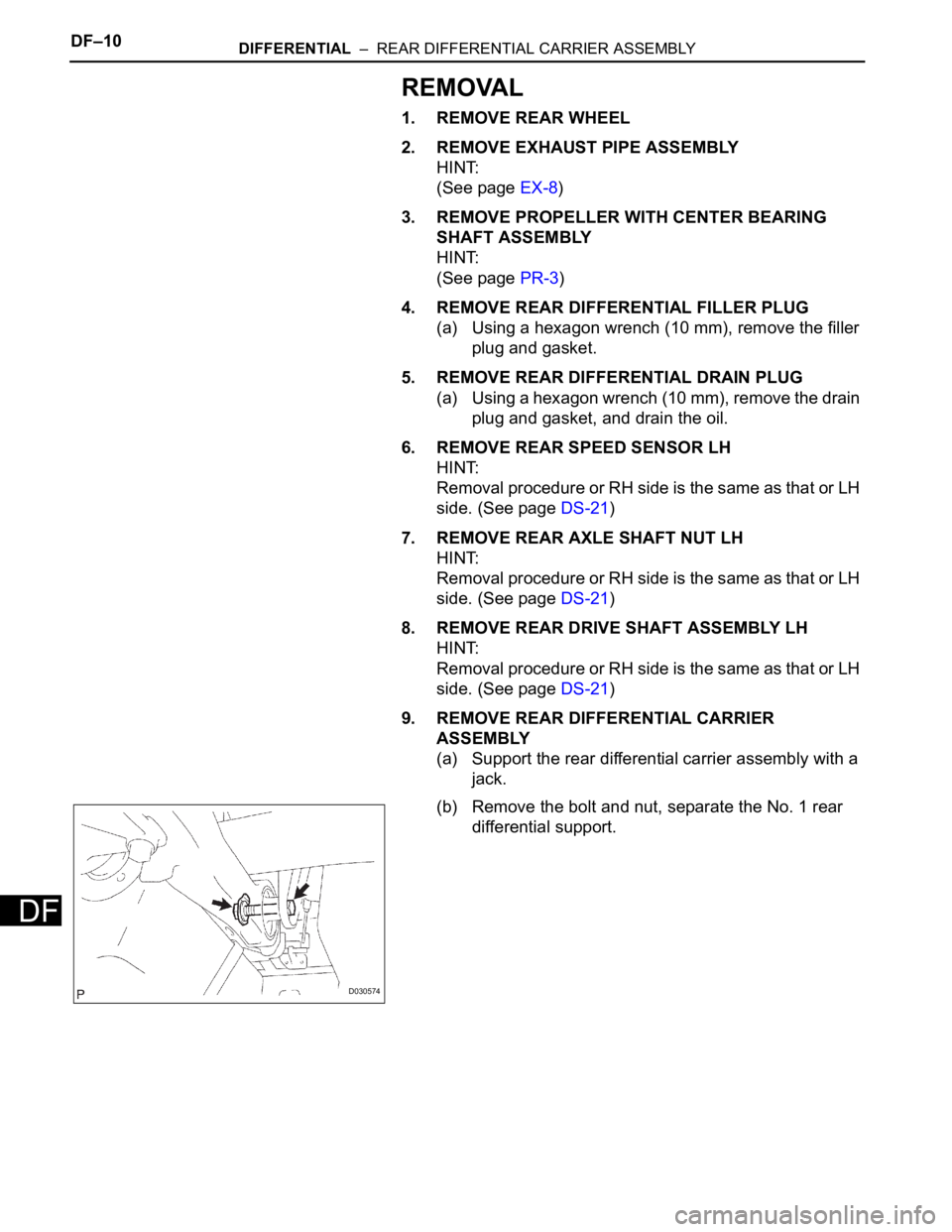
(b) Remove the bolt and nut, separate the No. 1 rear
differential support.
D030574
Page 2111 of 3000
DIFFERENTIAL – REAR DIFFERENTIAL CARRIER ASSEMBLYDF–11
DF
(c) Remove the 2 bolts, separate the rear differential
support assembly.
NOTICE:
Be careful not to drop the rear differential carrier
assembly.
10. REMOVE REAR DIFFERENTIAL SUPPORT
ASSEMBLY
(a) Remove the 3 bolts and rear differential support
assembly.
11. REMOVE REAR DIFFERENTIAL DYNAMIC DAMPER
(a) Remove the 2 bolts and rear differential dynamic
damper from the No. 1 rear differential support.
12. REMOVE NO. 1 REAR DIFFERENTIAL SUPPORT
(a) Remove the 2 bolts, 2 nuts and No. 1 rear
differential support.
INSTALLATION
1. INSTALL NO. 1 REAR DIFFERENTIAL SUPPORT
(a) Install the No. 1 rear differential support to the rear
differential carrier assembly with the 2 bolts and 2
nuts.
Torque: 85 N*m (867 kgf*cm, 63 ft.*lbf)
HINT:
Hold the bolt and tighten the nut.
D030575
D030577
D030576
C097682
C097682
Page 2112 of 3000

DF–12DIFFERENTIAL – REAR DIFFERENTIAL CARRIER ASSEMBLY
DF
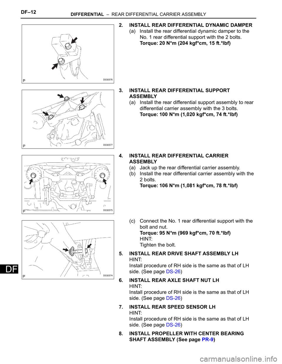
2. INSTALL REAR DIFFERENTIAL DYNAMIC DAMPER
(a) Install the rear differential dynamic damper to the
No. 1 rear differential support with the 2 bolts.
Torque: 20 N*m (204 kgf*cm, 15 ft.*lbf)
3. INSTALL REAR DIFFERENTIAL SUPPORT
ASSEMBLY
(a) Install the rear differential support assembly to rear
differential carrier assembly with the 3 bolts.
Torque: 100 N*m (1,020 kgf*cm, 74 ft.*lbf)
4. INSTALL REAR DIFFERENTIAL CARRIER
ASSEMBLY
(a) Jack up the rear differential carrier assembly.
(b) Install the rear differential carrier assembly with the
2 bolts.
Torque: 106 N*m (1,081 kgf*cm, 78 ft.*lbf)
(c) Connect the No. 1 rear differential support with the
bolt and nut.
Torque: 95 N*m (969 kgf*cm, 70 ft.*lbf)
HINT:
Tighten the bolt.
5. INSTALL REAR DRIVE SHAFT ASSEMBLY LH
HINT:
Install procedure of RH side is the same as that of LH
side. (See page DS-26)
6. INSTALL REAR AXLE SHAFT NUT LH
HINT:
Install procedure of RH side is the same as that of LH
side. (See page DS-26)
7. INSTALL REAR SPEED SENSOR LH
HINT:
Install procedure of RH side is the same as that of LH
side. (See page DS-26)
8. INSTALL PROPELLER WITH CENTER BEARING
SHAFT ASSEMBLY (See page PR-9)
D030576
D030577
D030575
D030574
Page 2113 of 3000
DIFFERENTIAL – REAR DIFFERENTIAL CARRIER ASSEMBLYDF–13
DF
9. FULLY TIGHTEN PROPELLER WITH CENTER
BEARING SHAFT ASSEMBLY (See page PR-10)
10. INSTALL REAR DIFFERENTIAL DRAIN PLUG
(a) Using a hexagon wrench (10 mm), install the drain
plug with a new gasket.
Torque: 49 N*m (500 kgf*cm, 36 ft.*lbf)
11. ADD DIFFERENTIAL OIL
(a) Fill the rear differential carrier assembly with hypoid
gear oil.
12. INSPECT DIFFERENTIAL OIL
HINT:
(See page DF-3)
13. INSTALL REAR DIFFERENTIAL FILLER PLUG
(a) Using a hexagon wrench (10 mm), install the filler
plug with a new gasket.
Torque: 49 N*m (500 kgf*cm, 36 ft.*lbf)
14. INSTALL REAR WHEEL
Torque: 103 N*m (1,050 kgf*cm, 76 ft.*lbf)
15. INSTALL EXHAUST PIPE ASSEMBLY
HINT:
(See page EX-10)
16. INSPECT FOR EXHAUST GAS LEAK
HINT:
(See page EX-12)
17. INSPECT AND ADJUST REAR WHEEL ALIGNMENT
HINT:
(See page SP-4)
18. INSPECT ABS SPEED SENSOR SIGNAL
HINT:
(See page BC-3)
Page 2114 of 3000

DF–16DIFFERENTIAL – REAR DIFFERENTIAL CARRIER
DF
DISASSEMBLY
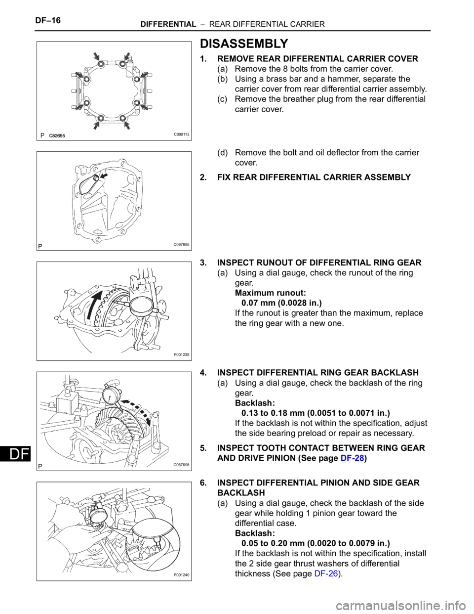
1. REMOVE REAR DIFFERENTIAL CARRIER COVER
(a) Remove the 8 bolts from the carrier cover.
(b) Using a brass bar and a hammer, separate the
carrier cover from rear differential carrier assembly.
(c) Remove the breather plug from the rear differential
carrier cover.
(d) Remove the bolt and oil deflector from the carrier
cover.
2. FIX REAR DIFFERENTIAL CARRIER ASSEMBLY
3. INSPECT RUNOUT OF DIFFERENTIAL RING GEAR
(a) Using a dial gauge, check the runout of the ring
gear.
Maximum runout:
0.07 mm (0.0028 in.)
If the runout is greater than the maximum, replace
the ring gear with a new one.
4. INSPECT DIFFERENTIAL RING GEAR BACKLASH
(a) Using a dial gauge, check the backlash of the ring
gear.
Backlash:
0.13 to 0.18 mm (0.0051 to 0.0071 in.)
If the backlash is not within the specification, adjust
the side bearing preload or repair as necessary.
5. INSPECT TOOTH CONTACT BETWEEN RING GEAR
AND DRIVE PINION (See page DF-28)
6. INSPECT DIFFERENTIAL PINION AND SIDE GEAR
BACKLASH
(a) Using a dial gauge, check the backlash of the side
gear while holding 1 pinion gear toward the
differential case.
Backlash:
0.05 to 0.20 mm (0.0020 to 0.0079 in.)
If the backlash is not within the specification, install
the 2 side gear thrust washers of differential
thickness (See page DF-26).
C098113
C067695
F001238
C067698
F001240
Page 2115 of 3000
DIFFERENTIAL – REAR DIFFERENTIAL CARRIERDF–17
DF
HINT:
Measure the backlash of the side gear with the side
gear shaft installed.
7. INSPECT RUNOUT OF REAR DRIVE PINION
COMPANION FLANGE SUB-ASSEMBLY
(a) Using a dial gauge, measure the runout of the
companion flange vertically and horizontally.
Maximum runout:
0.10 mm (0.0039 in.)
8. INSPECT DIFFERENTIAL DRIVE PINION PRELOAD
(a) Using a torque wrench, measure the preload of the
drive pinion.
Torque: 0.6 to 0.9 N*m (6 to 9 kgf*cm, 5.2 to 7.8
in.*lbf)
9. INSPECT TOTAL PRELOAD
(a) Using a torque wrench, measure the total preload.
Torque: 0.3 to 0.5 N*m (3 to 5 kgf*cm, 2.6 to 4.3
in.*lbf)
10. REMOVE REAR DIFFERENTIAL SIDE GEAR SHAFT
SUB-ASSEMBLY
(a) Using needle nose pliers, remove the 2 snap rings
from the 2 side gear shafts.
(b) Remove the 2 side gear shafts.
F001237E08
SA02352
SA02352
C067701