Page 2058 of 3000
TRANSFER – TRANSFER UNITTF–35
TF
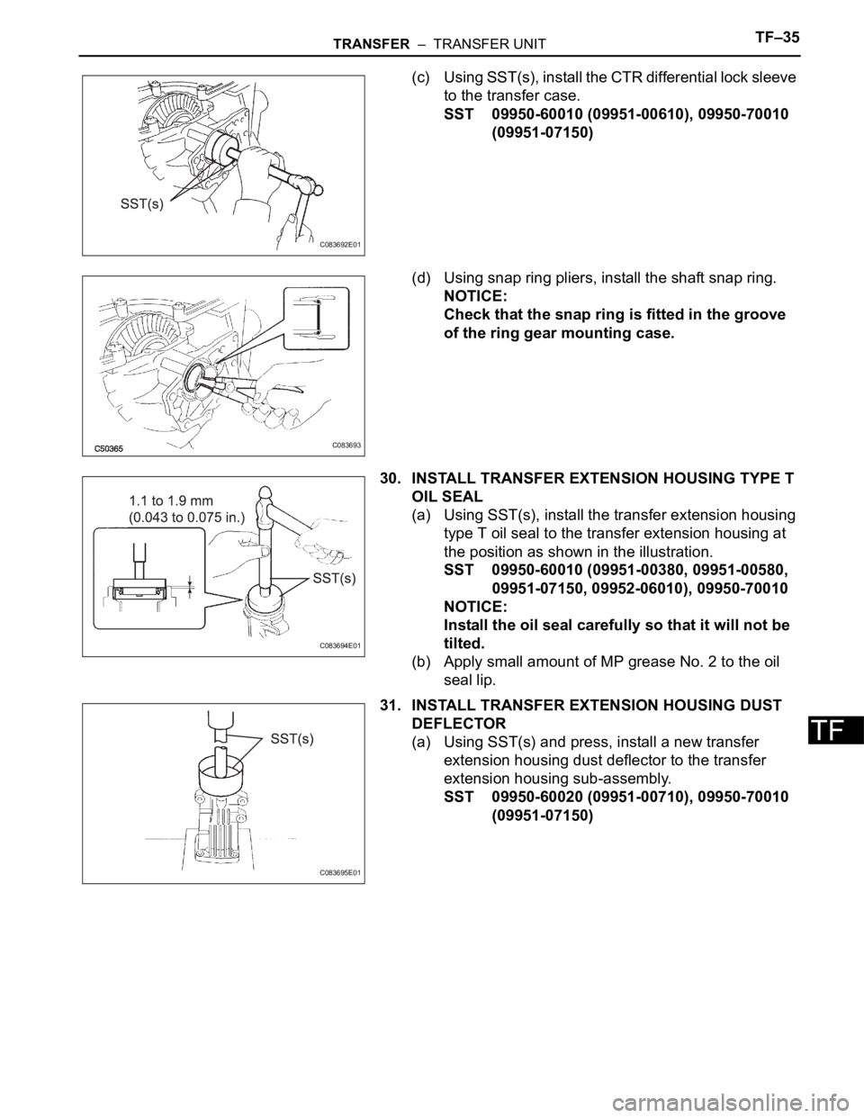
(c) Using SST(s), install the CTR differential lock sleeve
to the transfer case.
SST 09950-60010 (09951-00610), 09950-70010
(09951-07150)
(d) Using snap ring pliers, install the shaft snap ring.
NOTICE:
Check that the snap ring is fitted in the groove
of the ring gear mounting case.
30. INSTALL TRANSFER EXTENSION HOUSING TYPE T
OIL SEAL
(a) Using SST(s), install the transfer extension housing
type T oil seal to the transfer extension housing at
the position as shown in the illustration.
SST 09950-60010 (09951-00380, 09951-00580,
09951-07150, 09952-06010), 09950-70010
NOTICE:
Install the oil seal carefully so that it will not be
tilted.
(b) Apply small amount of MP grease No. 2 to the oil
seal lip.
31. INSTALL TRANSFER EXTENSION HOUSING DUST
DEFLECTOR
(a) Using SST(s) and press, install a new transfer
extension housing dust deflector to the transfer
extension housing sub-assembly.
SST 09950-60020 (09951-00710), 09950-70010
(09951-07150)
C083692E01
C083693
C083694E01
C083695E01
Page 2069 of 3000
PROPELLER SHAFT – PROPELLER SHAFT ASSEMBLY (for 4WD)PR–9
PR
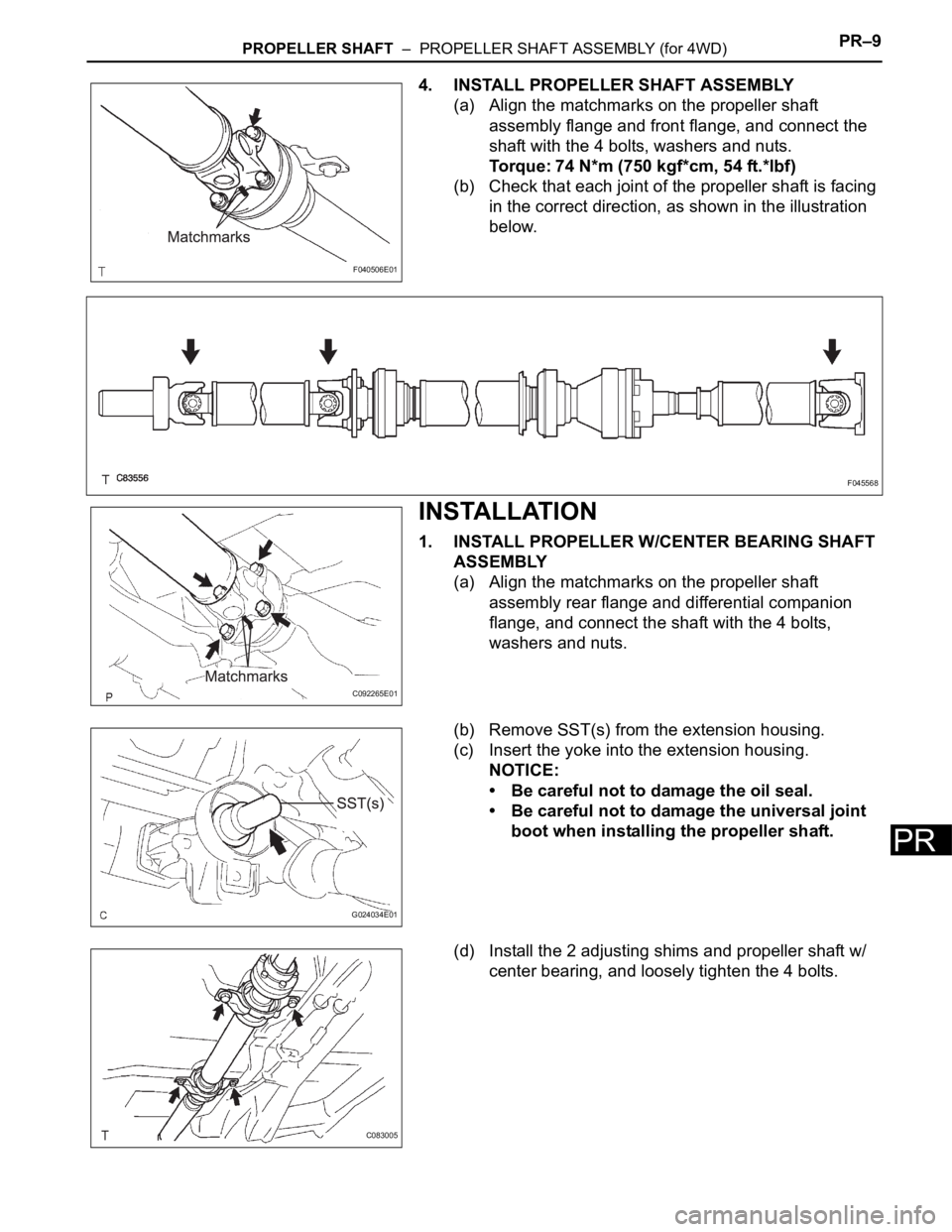
4. INSTALL PROPELLER SHAFT ASSEMBLY
(a) Align the matchmarks on the propeller shaft
assembly flange and front flange, and connect the
shaft with the 4 bolts, washers and nuts.
Torque: 74 N*m (750 kgf*cm, 54 ft.*lbf)
(b) Check that each joint of the propeller shaft is facing
in the correct direction, as shown in the illustration
below.
INSTALLATION
1. INSTALL PROPELLER W/CENTER BEARING SHAFT
ASSEMBLY
(a) Align the matchmarks on the propeller shaft
assembly rear flange and differential companion
flange, and connect the shaft with the 4 bolts,
washers and nuts.
(b) Remove SST(s) from the extension housing.
(c) Insert the yoke into the extension housing.
NOTICE:
• Be careful not to damage the oil seal.
• Be careful not to damage the universal joint
boot when installing the propeller shaft.
(d) Install the 2 adjusting shims and propeller shaft w/
center bearing, and loosely tighten the 4 bolts.
F040506E01
F045568
C092265E01
G024034E01
C083005
Page 2070 of 3000
PR–10PROPELLER SHAFT – PROPELLER SHAFT ASSEMBLY (for 4WD)
PR
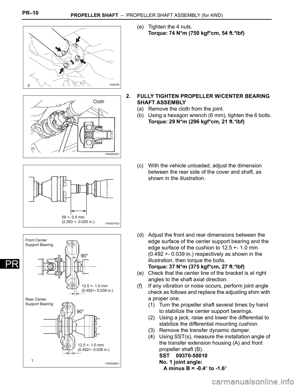
(e) Tighten the 4 nuts.
Torque: 74 N*m (750 kgf*cm, 54 ft.*lbf)
2. FULLY TIGHTEN PROPELLER W/CENTER BEARING
SHAFT ASSEMBLY
(a) Remove the cloth from the joint.
(b) Using a hexagon wrench (6 mm), tighten the 6 bolts.
Torque: 29 N*m (296 kgf*cm, 21 ft.*lbf)
(c) With the vehicle unloaded, adjust the dimension
between the rear side of the cover and shaft, as
shown in the illustration.
(d) Adjust the front and rear dimensions between the
edge surface of the center support bearing and the
edge surface of the cushion to 12.5 +- 1.0 mm
(0.492 +- 0.039 in.) respectively as shown in the
illustration, then torque the bolts.
Torque: 37 N*m (375 kgf*cm, 27 ft.*lbf)
(e) Check that the center line of the bracket is at right
angles to the shaft axial direction.
(f) If any vibration or noise occurs, perform joint angle
check as follows and replace the adjusting shim with
a proper one.
(1) Turn the propeller shaft several times by hand
to stabilize the center support bearings.
(2) Using a jack, raise and lower the differential to
stabilize the differential mounting cushion.
(3) Remove the transfer dynamic damper.
(4) Using SST(s), measure the installation angle of
the transfer extension housing (A) and front
propeller shaft (B).
SST 09370-50010
No. 1 joint angle:
A minus B = -0.4
to -1.6
C092265
F040503E01
F040527E03
F040528E01
Page 2071 of 3000
PROPELLER SHAFT – PROPELLER SHAFT ASSEMBLY (for 4WD)PR–11
PR
(5) Using SST(s), measure the installation angle of
the rear propeller shaft (C) and rear differential
(D).
SST 09370-50010
No. 2 joint angle:
C minus D = -1.6
to -3.6
If the measured angle is not within the
specification, adjust with the center support
bearing adjusting shim.
Center support bearing adjusting shim
thickness
(g) Install the transfer dynamic damper.
Torque: 26 N*m (260 kgf*cm, 19 ft.*lbf)
3. INSTALL EXHAUST PIPE ASSEMBLY
(a) Install exhaust pipe assembly (See page EX-10).
F040924E03
Thickness mm (in.) Thickness mm (in.)
3.2 (0.126) 4.5 (0.177)
6.5 (0.256) 9.0 (0.354)
Page 2075 of 3000
DS–22DRIVE SHAFT – REAR DRIVE SHAFT (for 4WD)
DS
REMOVAL
1. REMOVE REAR WHEEL
2. REMOVE TAIL EXHAUST PIPE ASSEMBLY (See page
EX-8)
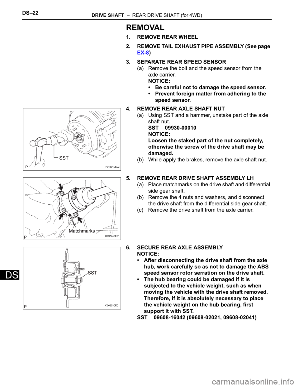
3. SEPARATE REAR SPEED SENSOR
(a) Remove the bolt and the speed sensor from the
axle carrier.
NOTICE:
• Be careful not to damage the speed sensor.
• Prevent foreign matter from adhering to the
speed sensor.
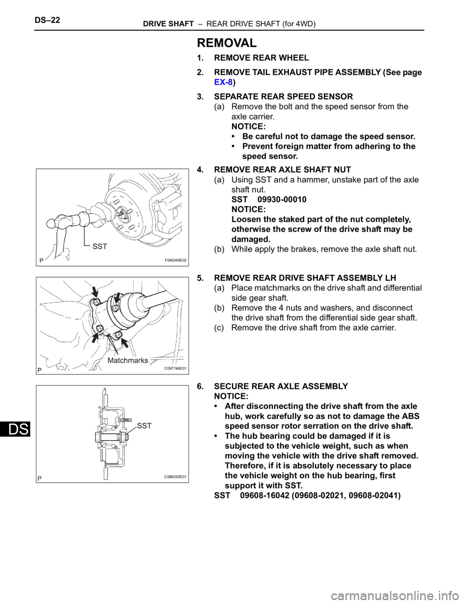
4. REMOVE REAR AXLE SHAFT NUT
(a) Using SST and a hammer, unstake part of the axle
shaft nut.
SST 09930-00010
NOTICE:
Loosen the staked part of the nut completely,
otherwise the screw of the drive shaft may be
damaged.
(b) While apply the brakes, remove the axle shaft nut.
5. REMOVE REAR DRIVE SHAFT ASSEMBLY LH
(a) Place matchmarks on the drive shaft and differential
side gear shaft.
(b) Remove the 4 nuts and washers, and disconnect
the drive shaft from the differential side gear shaft.
(c) Remove the drive shaft from the axle carrier.
6. SECURE REAR AXLE ASSEMBLY
NOTICE:
• After disconnecting the drive shaft from the axle
hub, work carefully so as not to damage the ABS
speed sensor rotor serration on the drive shaft.
• The hub bearing could be damaged if it is
subjected to the vehicle weight, such as when
moving the vehicle with the drive shaft removed.
Therefore, if it is absolutely necessary to place
the vehicle weight on the hub bearing, first
support it with SST.
SST 09608-16042 (09608-02021, 09608-02041)
F045049E02
C097746E01
C066030E01
Page 2097 of 3000
DS–22DRIVE SHAFT – REAR DRIVE SHAFT (for 4WD)
DS
REMOVAL
1. REMOVE REAR WHEEL
2. REMOVE TAIL EXHAUST PIPE ASSEMBLY (See page
EX-8)
3. SEPARATE REAR SPEED SENSOR
(a) Remove the bolt and the speed sensor from the
axle carrier.
NOTICE:
• Be careful not to damage the speed sensor.
• Prevent foreign matter from adhering to the
speed sensor.
4. REMOVE REAR AXLE SHAFT NUT
(a) Using SST and a hammer, unstake part of the axle
shaft nut.
SST 09930-00010
NOTICE:
Loosen the staked part of the nut completely,
otherwise the screw of the drive shaft may be
damaged.
(b) While apply the brakes, remove the axle shaft nut.
5. REMOVE REAR DRIVE SHAFT ASSEMBLY LH
(a) Place matchmarks on the drive shaft and differential
side gear shaft.
(b) Remove the 4 nuts and washers, and disconnect
the drive shaft from the differential side gear shaft.
(c) Remove the drive shaft from the axle carrier.
6. SECURE REAR AXLE ASSEMBLY
NOTICE:
• After disconnecting the drive shaft from the axle
hub, work carefully so as not to damage the ABS
speed sensor rotor serration on the drive shaft.
• The hub bearing could be damaged if it is
subjected to the vehicle weight, such as when
moving the vehicle with the drive shaft removed.
Therefore, if it is absolutely necessary to place
the vehicle weight on the hub bearing, first
support it with SST.
SST 09608-16042 (09608-02021, 09608-02041)
F045049E02
C097746E01
C066030E01
Page 2102 of 3000
PREPARATION – DIFFERENTIALPP–47
PP
RECOMMENDED TOOLS
09011-12301 Socket Wrench 30 mm
09025-00010 Torque Wrench (30 kgf-cm)
09040-00011 Hexagon Wrench Set
09044-00020 "TORX" Socket E10
Page 2103 of 3000
PP–48PREPARATION – DIFFERENTIAL
PP
EQUIPMENT
To r q u e w r e n c h
Dial gauge
Micrometer
Vernier caliper